http://www.scirp.org/journal/epe ISSN Online: 1947-3818
ISSN Print: 1949-243X
Study on Short Circuit Current Calculation
of Power System with UHVDC and
New Energy Source
Zaihua Li
1, Huan Yan
2, Yunting Song
1, Jincheng Guo
21China Electric Power Research Institute, Beijing, China
2State Grid Shaanxi Power Corporation Economic Research Institute, Xi’an, China
Abstract
With the development of power system, the level of short circuit current will increase accordingly. In general, the influence of the HVDC system and the new energy source is not considered in the calculation of the short circuit current. For the power grid that short circuit current level closes to the inter-rupting capacity of circuit breaker, it’s necessary to fully consider all kinds of influence factors, careful checking, so as to obtain more accurate calculation results of short circuit current. In 2018, two ±800 kV high-power Ultra High Voltage Direct Current (UHVDC) transmission projects will be connected with Shaanxi power grid, accompanied by a lot of concomitant fossil-fuel ge-nerating plants as power resource, and also a large number of new energy source, includes wind power generation and photovoltaic power generation. Around one of the UHVDC converter stations, short circuit current may ex-ceed the withstand limit of some certain circuit breakers. In order to get more accurate short circuit current calculation results, three measures are used: 1) contrastive calculation and analysis by algorithm based on schemes and algo-rithm based on power flow; 2) analysis the influence of UHVDC by electro-magnetic transient and electromechanical transient hybrid simulation; 3) con-sidered a detailed model of Doubly Fed Induction Generator (DFIG) with low voltage ride through characteristics. The calculation results shows that: in the typical operation mode of Shaanxi power grid of 2018, the original calculation results by conventional calculation method are coincident with the results by considering the influence of algorithms, UHVDC and DFIG in large, in which: the results of the algorithm based on power flow are smaller than that of the algorithm based on schemes about 2 - 8 kA; the steady values of the short circuit current provided by UHVDC converterstation (includes rectifi-ers and smoothing capacitors) are about 0 - 3 kA; the steady values of the How to cite this paper: Li, Z.H., Yan, H.,
Song, Y.T. and Guo, J.C. (2017) Study on Short Circuit Current Calculation of Power System with UHVDC and New Energy Source. Energy and Power Engineering, 9, 625-634.
https://doi.org/10.4236/epe.2017.94B068
short circuit current provided by DFIG are about 0 - 5 kA. The calculation results can provide reference for the selection of the circuit breaker, and it can be verified by fault recording data in the future.
Keywords
Short Circuit Current, UHVDC, New Energy Source, Hybrid Simulation
1. Introduction
With the development of power system, the level of short circuit current will in-crease accordingly. In general, the influence of the HVDC system and the new energy source is not considered in the calculation of the short circuit current. However, for the power grid that short circuit current level closes to the inter-rupting capacity of circuit breaker, it’s necessary to fully consider all kinds of in-fluence factors, careful checking, so as to obtain more accurate calculation re-sults of the short circuit current.
In the year of 2018, two ±800 kV high-power Ultra High Voltage Direct Cur-rent (UHVDC) transmission projects will be connected with Shaanxi power grid, accompanied by a lot of fossil-fuel generating plants as power resource, and also a large number of new energy source, includes wind power generation and photovoltaic power generation. Around one of the UHVDC converter stations, short circuit current may exceed the withstand limit of some certain circuit breakers. In fact, the short circuit current calculation results by means of con-ventional calculation method may be somewhat conservative.
In order to get more accurate short circuit current calculation results, three measures are used in the paper: 1) contrastive calculation and analysis by algo-rithm based on schemes and algoalgo-rithm based on power flow; 2) analysis the in-fluence of UHVDC by electromagnetic transient and electromechanical transient hybrid simulation; 3) considered a detailed model of DFIG with low voltage ride through characteristics [1].
2. Algorithm of Short Circuit Current Calculation
2.1. Algorithm Based on Schemes
In the calculation of short circuit current, the principle formula includes:
“ 3 *
k k
k
U I
Z
= (1)
where Uk is the open circuit voltage of short circuit point, in BPA it’s often fixed
to 1.05 Un, Zk is equivalent impedance of short circuit point, other hypotheses
2.2. Algorithm Based on Power Flow
In the calculation of short circuit current of the algorithm, the principle formula is as same as the above algorithm. Where Uk is the open circuit voltage of short
circuit point, in BPA it comes from the result of power flow calculation. Zk is
equivalent impedance of short circuit point, other hypotheses and conditions are as same as the above algorithm based on schemes.
2.3. Brief of Relevant Standards
At present, the main relevant international standards of calculation of short cir-cuit current includes IEC60909 series standards and ANSI/IEEE/UL series stan-dards. Furthermore, in order to guide the calculation of short circuit currents in DC auxiliary installations in power plants and substations, IEC 61660 series standards are setup. Many countries or enterprises developed their own national standards, industry standards or enterprise standards based on these series standards and combined with their actual situation. In china, the national stan-dards, industry standards or enterprise standards of short circuit current calcu-lation are no exception, all based on the IEC60909 or IEC 61660 series standards, combined with the actual situation of the specific application areas, is almost equivalent to utilize the two series of standards, but a slight modification.
The general approach is divided into two steps. At first the short circuit cur-rents of the individual sources are calculated separately. Subsequently, the indi-vidual currents are superposed resulting in an overall short circuit current of the system.
The international simulation software of calculation of short circuit current includes BPA of Bonneville Power Administration, PSS/E and NETOMAC of Siemens, ARENA of EDF, PSAPAC/ LISP of EPRI, NEPLAN of ABB, EXTAB of TEPCO. In china, the main software includes PSD-BPA and PSASP. They all abide by these above series standards by and large. In the paper, PSD-BPA is adopted, and all kinds of hypotheses and conditions are based on PSD-BPA [2] [3].
3. Short Circuit Current from HVDC
3.1. Configuration of HVDC Converter
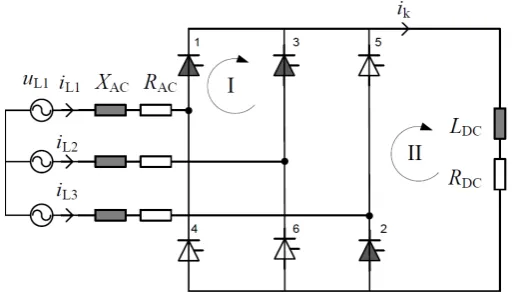
this paper, UHVDC based on LCC is considered. The Equivalent circuit of a six-pulse bridge at a short circuit on the DC side is shown as Figure 1.
The six-pulse bridge is the basic element of a CSC-HVDC, which is shown in Figure 1 at a short circuit on the DC side. The largest short circuit current of a single bridge can be expected, if a line-to-line short circuit occurs directly at the terminal (RDC = 0, LDC = 0). For this particular case the DC short circuit current
can be derived according to the loops I and II shown in Figure 1. In this instant the diodes D1, D3 and D2 are conducting.
3.2. Rectifier
The resistance RDC and the inductance LDC of the DC system comprise the
para-meters of the rectifier, the smoothing reactor and the line. The calculation of the characteristic parameters of the short circuit current is based on the corres-ponding values of the AC and DC system. The quasi-steady-state short circuit current of a rectifier in a three-phase bridge connection is
c 3 2
3
n rTLV
kD D
rTHV N
U U
I
U Z
λ π
⋅
= ⋅ ⋅ ⋅ (2)
where UN is the nominal voltage of the AC system, ZN the system impedance, UrTLV/UrTHV the ratio of the rated voltages of the secondary and primary
trans-former side and λD considers the influence of the DC side resistance.
The peak short circuit current ipD is calculated using:
pD D kD
i =k ⋅I (3)
The factor kD depends on the ratio of the inductances LDC/LN and the
parame-ters RN, RDC and XN.
The calculation of the time constantsτ1D, τ2Dand the time to peak tpD is
de-scribed in the reference [2].
3.3. Capacitor
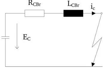
The equivalent circuit diagram of the capacitor is depicted in Figure 2. The re-sistance RCBr and the inductance LCBr include the resistances and inductances of
[image:4.595.245.502.571.717.2]the capacitor and of the connection to the line.
Figure 2. Equivalent circuit diagram of the capacitor to calculate the short circuit current.
The quasi-steady-state short circuit current of the capacitor is zero:
0
kC
I = (4)
The peak short circuit is calculated by using
C pC C
CBr E
i k
R
= ⋅ (5)
where kC depends on the eigen-frequency ω0 and the decay coefficient δ. The
corresponding calculation of ω0 respectively δ and the equations for τ1C, τ2C and tpC are specified in the reference [2].
3.4. Electromagnetic Transient and Electromechanical
Transient Hybrid Simulation
When a fault or an operation happens, electromagnetic transient procedure and electromechanical transient procedure occur in power system. Usually we ana-lyze the two procedures individually, because uniform analysis is very complex and impractical. We use electromechanical transient simulation to analyze elec-tromechanical transient procedure and electromagnetic transient simulation to analyze electromagnetic transient procedure. Electromechanical transient pro-cedure varies slowly compared with electromagnetic transient propro-cedure, there-fore the integration time step of electromechanical transient simulation is much larger than that of electromagnetic transient simulation. Usually the integration time step of electromechanical transient simulation is 10 milliseconds while that of electromagnetic transient simulation is about 20 - 200 microseconds.
Electromechanical transient simulation can simulate quite large power system, based on three-sequence phasor model with much larger time step. While, Elec-tromagnetic transient simulation, based on three-phase instant value model, can analyze electromagnetic transient procedure and represent those power elec-tronic devices very easily, while the scale of the system simulated is very limited for its much larger computation amount. Hybrid simulation combines the ad-vantages of the both. With hybrid simulation, we can analyze the electromag-netic transient procedure appearing in a special small network under the back-ground of a large power system.
ge-nerators in electromechanical transient network, Norton equivalent admittance matrix becomes asymmetric when transformed from three sequences to ABC three phases. PSD-BPAFDS (Full Dynamic Process Simulation Software) pro-vides the performance.
4. Short Circuit Current from Wind Farm
To exploit and utilize new energy source is the need of the time and hence its development is on the rise from last couple of decades. Renewable energy source is a major new energy source. Wind power generation and photovoltaic genera-tion are the most popular two kinds of renewable energy source. The short cir-cuit current caused by wind power generation or photovoltaic generation is usually not considered.
DFIG is the most widely used limited variable speed generator. The four qua-drant operation of converters allows DFIG provides decoupled control of active and reactive power. The ability to control reactive power is beneficial for grid voltage support. Whereas the case of DFIG employing an induction machine, the short circuit current is governed by the machine characteristics. With the development of wind power generation, short circuit current becomes more and more prominent, so it’s not appropriate to neglect short circuit current from wind farm [5].
4.1. Modeling of DFIG
DFIG can be described as an induction machine model in space vector notation. The space vector model is subjected to a reference frame transformation to get decoupled d-q model. The reference frame is usually aligned with stator flux ref-erence frame. This facilitates in decoupling the active and reactive power of the machine. The terminal rotor voltage vector which is a control input in case of a DFIG will then be able to decide idr and iqr independently. The detailed model of
a DFIG is a fifth order model having two voltage equations for stator and rotor each.
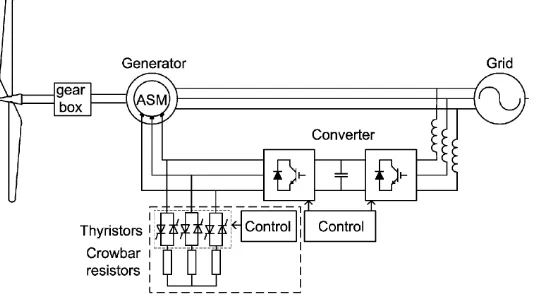
[image:6.595.242.512.567.715.2]The typical structure of a DFIG system with crowbar protection using a wound rotor induction machine is shown as below Figure 3 [6].
In the procedure of calculation, crowbar resistance is often assumed to be connected to rotor winding throughout the duration of the fault. The assump-tion is valid because crowbar activaassump-tion is fast and completed in few millise-conds. It also assumes constant generator speed during fault conditions. The above assumption can cause errors in fault current prediction but is considered for simplification. The magnetic nonlinearities are neglected in this analysis. Considering the effect of saturation on leakage reactance may increase the fault current levels.
The decaying stator natural flux will induce an emf in rotor of frequency, then the emf induced in rotor winding will cause a current to flow limited by crowbar resistance. This current will in tum produce a flux which will oppose the stator flux. This will be the case in a steady state condition if stator natural flux persists. Thus DFIG fault current analysis is governed by crowbar resistance. Due to in-troduction of crowbar the AC component present during the fault decays at much faster rate. This causes the stator fault current to be entirely DC compo-nent. The interruption of DC current may be a problem for AC circuit breaker. This could become even more hazardous as we move towards DFIGs with higher MVA ratings as they have a higher stator time constant.
4.2. Short Circuit Current Components
The short-circuit current of an idle running machine will be determined. Neg-lecting the mechanical losses, the machine rotates at the synchronous rotational speed ωs. The stator resistance can be neglected in steady state. Before the
oc-currence of the short circuit, the rotor current is zero: Ir = 0. The stator current
is:
s s
s
jw t jw t
jw t s s
s
s s s
V e V e
I e
jX jw L
= = (6)
The maximum stator current of an induction machine in case of a short cir-cuit at the stator terminals is:
2 2 ,max 2 (1 ) s r T T T T s s s V
i e e
X σ
− −
′ ′
= + −
′ (7)
The time constant for the damping of the dc components in stator and rotor are defined as below:
s s s L T R ′
′ = (8)
r r r L T R ′
′ = (9)
Due to asymmetry of fault, the stator flux will have positive and negative se-quence components. The magnitude and phase angle of these components de-pends on the type of fault.
s s
jw t
jw t s
s s cb V e I e jX R =
+ (10)
And the transient time constant of the rotor becomes:
r r r cb L T R R ′ ′ =
+ (11)
The two exponential functions inside the brackets in (7) are based on the as-sumption that the rotor and stator flux are 180˚ out of phase after half a period, implying that the current reaches its maximum value at t = T/2. This assumption is approximately valid for an induction machine, where the slip is small and where the stator and rotor flux are approximately in phase with each other, at the moment the fault occurs. A DFIG can however operate at a much larger slip. This implies that at the moment of the fault, the two flux vectors are not in phase with each other.
Taking into account these differences between an induction machine and a DFIG, then (7) becomes:
Δ Δ
,max 2 2
2 (1 ) s r T T T T s s s cb V
i e e
X R σ − − ′ ′ = + −
′ + (12)
A larger bypass resistance will result in a smaller Tr′. At the same moment, Δt
decreases. As a result, the term inside the brackets in (12) stays approximately constant. As a rough approximation, the maximum stator current is then given as: 2 2 ,max 1.8 s s s cb V i X R ≈
′ + (13)
5. Comparison of Results
This research uses the PSD-SCCPC short circuit current calculation program (Version 2.5.2) for the calculation of Shaanxi power grid 330 kV - 750 kV bus three-phase short circuit and single phase short circuit current, the following specific principles are abided:
1)Consider the static load, and not consider the motor load.
2)Consider shunt capacitor compensation, inductance compensation and filter capacitor compensation in the positive sequence network.
3)Consider line charging power.
4)Consider biggest operation and completely connected mode, namely consi-dering the short circuit current provided by the outage unit.
5)Consider the line, transformer and generator impedance. 6)Consider the actual ratio as the ratio of transformer.
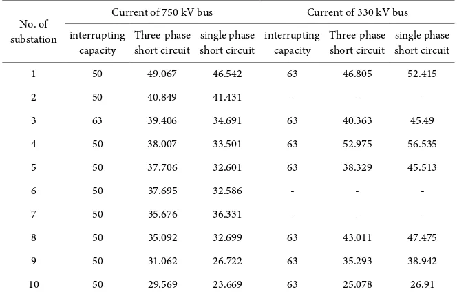
Under the above principles and algorithms, 750 kV bus short circuit currents in Shaanxi power grid in summer peak operation mode of 2018 are shown partly as follows Table 1.
Table 1. Bus short circuit current by the algorithm based on schemes (Unit: kA).
No. of substation
Current of 750 kV bus Current of 330 kV bus interrupting
capacity Three-phase short circuit single phase short circuit interrupting capacity Three-phase short circuit short circuit single phase 1 50 49.067 46.542 63 46.805 52.415
2 50 40.849 41.431 - - -
3 63 39.406 34.691 63 40.363 45.49 4 50 38.007 33.501 63 52.975 56.535 5 50 37.706 32.601 63 38.329 45.513
6 50 37.695 32.586 - - -
7 50 35.676 36.331 - - -
8 50 35.092 32.699 63 43.011 47.475 9 50 31.062 26.722 63 35.293 38.942 10 50 29.569 23.669 63 25.078 26.91
Table 2. Comparison of by different short circuit current algorithms (Unit: kA).
No. of substation
Current of Three-phase short circuit Current of single phase short circuit Algorithm 1 Algorithm 2 difference Algorithm 1 Algorithm 2 difference 1 49.067 41.336 7.731 46.542 40.666 5.876 2 46.805 40.231 6.574 52.415 46.228 6.187 3 38.007 34.499 3.508 33.501 30.934 2.567 4 52.975 49.167 3.808 56.535 52.79 3.745 5 32.681 30.102 2.579 27.938 26.026 1.912 6 43.464 40.525 2.939 40.371 37.902 2.469 7 38.319 32.746 5.573 45.497 38.846 6.651 8 41.697 38.789 2.908 38.3 35.932 2.368
According to the above tables, the results obtained by the algorithm based on power flow are less than that by the algorithm based on schemes with about 2 - 8 kA.
According to the calculation, the maximum value of DC component of short circuit current at the short circuit point is about 4.5 kA, the steady values of the short circuit currents from UHVDC varies from about 0 - 3 kA.
An analysis of short circuit current of three different DFIGs of rating l.5 MW, 4.5 MW and 7.5 MW shows an increase in short circuit current magnitude with increase in size of machine. The increase in size of DFIG also may cause the DC component of short circuit current to persist for longer duration [7]. According to the calculation, the steady values of the short circuit current from wind farm varies from about 0 - 5 kA.
[image:9.595.209.540.337.508.2]6. Conclusions
The level of short circuit current obtained by the algorithm based on power flow is lower than that by the algorithm based on schemes to some certain extent.
The crowbar resistance had significant impacts on short circuit current levels and time constants for stator and rotor. With use of crowbar resistance the AC component of short circuit current decayed much faster leaving a situation of pure DC current. The value of crowbar resistance might be more difficult to ob-tain. Therefore, it’s very necessary to investigate how it can be determined.
With combined consideration of the influence of algorithms, UHVDC and DFIG, the results are coincident with the results by conventional calculation method by and large.
References
[1] Huang, X.L., Liu, Z.R., Zhu, R.J., Yang, Z.H., Zhou, G., et al. (2010) Impact of Pow-er System Integrated with Large Capacity of Variable Speed Constant Frequency Wind Turbines, Transactions of China Electrotechnical Society, 25, 142-149.
[2] IEC 61660-1: 1997, Short Circuit Currents – Short Circuit Currents in D.C. Aux-iliary Installations in Power Plants and Substations – Part 1: Calculation of Short Circuit Currents, June 1998.
[3] IEC 60909-0: 2001, Short-Circuit Currents in Three-Phase A. C. Systems – Part 0: Calculation of Currents, July2001.
[4] Andreas, W., Benedikt, J. and Gerd, B. (2013) Contribution of HVDC converters to the DC Short Circuit Current. Proceedings of the 48thInternational Universities’ Power Engineering Conference, 1-6.
[5] Muljadi, E., Samaan, N., Gevorgian, V. and Li, J. and Pasupulati, S. (2010) Short Circuit Current Contribution for Different Wind Turbine Generator Types. Pro-ceedings of IEEE Power and Energy Society General Meeting, 1-8.
https://doi.org/10.1109/PES.2010.5589677
[6] Adio, O.S., Lin, X.N., Zhao, F. and Bo, Z.Q. (2013) Short Circuit Analysis for Inte-gration of l0MW Windfarm in Nigeria at the PCC. Proceedings of IEEE Power & Energy Society General Meeting, 1-5.
https://doi.org/10.1109/PESMG.2013.6672196
[7] Bhatia, R. and Bahirat, H.(2016)Short Circuit Currents of DFIG based Wind Tur-bines. Proceedings of IEEE 6th International Conference on Power Systems (ICPS), 1-6. https://doi.org/10.1109/ICPES.2016.7584193
Submit or recommend next manuscript to SCIRP and we will provide best service for you:
Accepting pre-submission inquiries through Email, Facebook, LinkedIn, Twitter, etc. A wide selection of journals (inclusive of 9 subjects, more than 200 journals)
Providing 24-hour high-quality service User-friendly online submission system Fair and swift peer-review system
Efficient typesetting and proofreading procedure
Display of the result of downloads and visits, as well as the number of cited articles Maximum dissemination of your research work