ISSN Print: 1913-3715
Simulation Research on Ran-Assisted WLAN
Offloading Scheme
Yuanying Shi, Guangyue Lu, Junmin Jiang
1, Jiali Zhang
School of Telecommunication and Information Engineering, Xi’an University of Posts and Telecommunications, Xi’an, China
Abstract
Wireless Local Area Network (WLAN) offloading is an important approach to address the data traffic challenge faced by Long Term Evolution (LTE) net-work. Legacy offloading solutions based on the core network suffer from the limitations of load unbalance and user experience degradation. To solve this problem, 3GPP has recently proposed a radio access network (RAN) assisted WLAN offloading scheme. In this article, we thoroughly analyze the perfor-mance of this new scheme, with emphasis on the RAN auxiliary parameters and control rules defined in it. Furthermore, two kinds of offloading algo-rithms based on this scheme are proposed and compared with the traditional solutions by simulation. Results show that the RAN-assisted offloading scheme can increase average user throughput and leverage resources available in both LTE and WLAN systems.
Keywords
LTE, WLAN, RAN-Assisted, Traffic Offloading
1. Introduction
With the increasing popularity of modern terminals such as smart phones and tablets, the amount of mobile data traffic has recently been doubling every year. This unprecedented traffic demands have imposed significant challenge on Long Term Evolution (LTE) network, which forces mobile network operators to in-vestigate ways to offload data traffic to different Radio Access Networks (RANs), such as Wireless Local Area Network (WLAN).
An effective offloading strategy plays an important role for efficiently use of the available resources in both LTE and WLAN networks as well as improve-ment of the end user’s experience. A number of literatures such as [1] [2] [3] [4] [5] have discussed this topic and presented algorithms based on Access Network
How to cite this paper: Shi, Y.Y., Lu, G.Y., Jiang, J.M. and Zhang, J.L. (2017) Simulation Research on Ran-Assisted WLAN Offloading Scheme. Int. J. Communications, Network and System Sciences, 10, 324-332.
https://doi.org/10.4236/ijcns.2017.105B032 Received: July 10, 2017
Discovery and Selection Function (ANDSF) [6]. However, these ANDSF-based solutions mainly focus on the core network (CN) and cannot adapt well to dy-namic changes of radio environments (e.g. the access node load and channel quality), hence resulting in poor user experience or inadequate utilization of WLAN resources [7].
To realize effective balancing of user data traffic between LTE and WLAN networks, 3GPP has recently defined a new feature named “RAN-assisted WLAN interworking” in Release 12, which can provide the user equipment (UE) with information of radio signal strength and the load level of LTE cells and WLAN Access Points (APs). Several offloading algorithms based on this scheme have been proposed in [8] [9] [10]. However, to the authors’ best knowledge, few works have studied it in a holistic view. In this paper, we will explore the RAN-assisted offloading scheme in detail and evaluate its performance by sys-tem simulation.
The remaining of the paper is organized as follows. Detailed description and analysis of the RAN-assisted WLAN offloading scheme is given in Section 2. Two kinds of RAN-assisted offloading algorithms for performance evaluation are proposed in Section 3. Simulation results and discussion are provided in Sec-tion 4 followed by conclusions in SecSec-tion 5.
2. RAN-Assisted WLAN Offloading Scheme
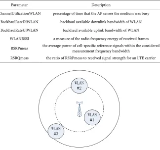
RAN-assisted WLAN offloading scheme is an enhancement to existing CN- based solutions. In the latter case, the ANDSF only provides a UE with the iden-tification of offloadable WLANs. Without knowledge of the WLAN load level and its quality of service, the UE can just adopt simple offloading policy, e.g. offloading when the indicated WLAN is available. Obviously, this kind of policy might result in poor user experience if the target WLAN is already overloaded. Hence, in RAN-assisted offloading, an eNodeB should collect more information about itself and neighboring WLAN networks, such as load condition, backhaul quality, offload preference, etc. An eNodeB might obtain WLAN information directly through an interface between them, or from the UE’s reports. Since RAN-assisted offloading is a network assisted UE controlled solution, the eNodeB should send the UE the collected information as RAN-assisted parame-ters which will be used in offloading algorithms pre-configured in the UE. Table 1 lists the parameters defined in 3GPP TS 36.304 [11]. Deserved to be men-tioned, an eNodeB doesn’t need to use all of the parameters simultaneously, which means it can arbitrarily combine them. Accordingly, a UE should use the same set of parameters as its serving eNodeB.
the WLAN to decide whether to offload or not. For example, the UE will offload traffic to WLAN only if both the measured Reference Signal Received Power (RSRP) is below RSRPThresholdLTE->WLAN and WLAN channel utilization is
be-low ChannelUtilizationThresholdLTE->WLAN. RSRPThresholdLTE->WLAN is the
threshold of parameter RSRPmeas and ChannelUtilization ThresholdLTE->WLAN is that of ChannelUtilizationWLAN. The subscript means they are used for off-loading from LTE to WLAN. Obviously, this policy provides an opportunity for the UE to make a more rational choice than just offloading traffic to WLAN when available.
[image:3.595.212.537.412.715.2]There are two kinds of control granularity for RAN-assisted offloading scheme: coarse-grained and fine-grained. In the coarse-grained mechanism, an eNodeB sets the same thresholds for all target WLAN networks within a cell’s coverage. It broadcasts the thresholds values in system information message to all UEs. In this case, the thresholds can’t reflect differences between WLAN networks, e.g. their locations, so it can’t balance the network load effectively. For the offloading scenario shown in Figure 1, the outermost circle represents a cell’s actual coverage region and the dotted circle represents the range corre sponding to RSRPThresholdLTE->WLAN. It is clear that a UE will not offload traffic to WLAN #1 even if it is in light load state because it doesn’t meet the rule that the measured RSRP is below RSRPThresholdLTE->WLAN. Then WLAN #1 will not be fully utilized unless the cell reduces the scope of the dotted circle by increas-
Table 1. RAN-assisted parameters defined in TS 36.104.
Parameter Description
ChannelUtilizationWLAN percentage of time that the AP senses the medium was busy BackhaulRateDlWLAN backhaul available downlink bandwidth of WLAN BackhaulRateUlWLAN backhaul available uplink bandwidth of WLAN
WLANRSSI a measure of the radio frequency energy of received frames RSRPmeas the average power of cell-specific reference signals within the considered measurement frequency bandwidth RSRQmeas the ratio of RSRPmeas to received signal strength for an LTE carrier
Figure 1. An example offloading scenario. WLAN
#1
WLAN #3
ing RSRPThresholdLTE->WLAN. Hence, a fine-grained offloading control mecha-nism is required.
In the fine-grained mechanism, an eNodeB sets indiviual thresholds values for each UE. Thus it has a chance to take into account the UE’s location and its sur-rounding radio environments. The thresholds must be sent to the specific UE by dedicated signaling. Therefore, this mechanism is only suitable for UE in LTE connected state. However, the thresholds values may keep valid for a period of time. During this period, the UE is allowed to use these values even if it has gone to idle state or has associated to a WLAN AP.
3. Offloading Algorithms for Evaluation
To evaluate the performance of the RAN-assisted offloading scheme, we present two specific algorithms with different control granularity. A simple algorithm based on the legacy offloading scheme is also described below for simulation comparison.
3.1. Algorithm 1
This algorithm represents the traditional CN-based offloading solutions and is used as a reference for performance comparison. In this algorithm, a UE doesn’t take into account the RAN-assisted information when it selects an offloading target. It means the UE will offload data traffic to WLAN networks whenever it finds the Received Signal Strength (RSS) of a WLAN AP is above the minimum threshold, which is −96 dBm in our simulation.
3.2. Algorithm 2
This algorithm represents the coarse-grained mechanism described in Section 2. It is based on the algorithm presented in [9] while employs a self-optimized strategy for thresholds adjustment.
In this algorithm, an eNodeB only monitors for changes in the LTE cell load and adjusts the RSRP thresholds accordingly. The LTE cell load is defined as the physical resource block utilization percentage in uplink or down-link direction. Two LTE cell load thresholds are pre-defined: LoadThreshLTE-high and LoadThreshLTE-low. If the LTE cell load is higher than LoadThreshLTE-high, RSRP-ThresholdLTE->WLAN will be increased to offload more data traffic to WLAN. If the LTE cell load is under
LoadThreshLTE-low, RSRPThresholdWLAN->LTE will be decreased to bring more
traf-fic back to LTE.
A UE connected to LTE should check if the measured RSRP is below
RSRPThresholdLTE->WLAN and if it can find a WLAN AP with RSS higher than
RSSThresholdLTE->WLAN. If both conditions are met, the UE will offload its traffic
to WLAN. A UE associated with a WLAN AP will execute similar operation, i.e.
if the RSRP is above RSRPThresholdWLAN->LTE and the RSS is lower than
RSSThresholdWLAN->LTE, it will bring the traffic back to LTE.
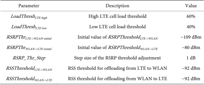
Table 2. Main parameters for Algorithm 2.
Parameter Description Value LoadThreshLTE-high High LTE cell load threshold 60%
LoadThreshLTE-low Low LTE cell load threshold 40%
RSRPThrLTE->WLAN-initial Initial value of RSRPThresholdLTE->WLAN −109 dBm
RSRPThrWLAN->LTE-initial Initial value of RSRPThresholdWLAN->LTE −80 dBm
RSRP_Thr_Step Step size of the RSRP threshold adjustment 1 dB RSSThresholdLTE->WLAN RSS threshold for offloading from LTE to WLAN −92 dBm
RSSThresholdWLAN->LTE RSS threshold for offloading from WLAN to LTE −92 dBm
3.3. Algorithm 3
This algorithm represents the fine-grained mechanism described in Section 2 and is an improvement of Algorithm 2. The algorithm takes into account both the LTE cell load and the WLAN load. The WLAN load is represented by the percentage of average channel busy time of a WLAN AP [10]. In addition to the LTE cell load thresholds described in Algorithm 2, two more load thresholds are defined for WLAN: LoadTheshAP-high and LoadThreshAP-low. The RSRP and RSS thresholds are set and adjusted for each pair of LTE cell and WLAN AP. Table 3 describes the adjustment rules under various load conditions.
Then the eNodeB should send appropriate thresholds values to UEs based on their locations. Here we choose the values corresponding to the UE’s serving cell and its nearest WLAN AP. The UE’s operation is the same as that described in Algorithm 2.
Main parameters for this algorithm and their simulation values are captured in Table 4. Parameters already used in Algorithm 2 are not listed in the table.
4. Simulation Scenario and Results
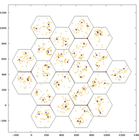
To evaluate the proposed algorithms, we adopt a simulation scenario of an out-door high traffic shopping center as shown in Figure 2. The deployment in-cludes 7 LTE macro sites (red points in Figure 2) and 3 randomly distributed WLAN APs (blue points) for each LTE cell. Hence, the total number of LTE cells and WLAN APs are 21 and 63 respectively. The LTE network operates at 2 GHz and uses a bandwidth of 10 MHz. The WLAN system modelling follows the IEEE 802.11n standard and operates at 2.4 GHz with a bandwidth of 20 MHz. The transmission power of the eNodeB and the AP is 46 dBm and 16 dBm re-spectively.
50 UEs (orange points) are placed within each LTE cell coverage. Among them, 14 are randomly distributed, and 12 are concentrated around each AP. All UEs are static and can receive control messages from the eNodeB all the time.
Figure 2. Simulation scenario.
Table 3. Adjustment rules for thresholds.
LTE cell WLAN AP Adjustment rule overloaded overloaded no need to adjust overloaded not overloaded increase RSRPThresholdLTE->WLAN,
decrease RSSThresholdLTE->WLAN
not overloaded overloaded Increase RSSThresholdLTE->WLAN,
decrease RSRPThresholdLTE->WLAN
underloaded not underloaded decrease RSRPThresholdWLAN->LTE,
increase RSSThresholdWLAN->LTE
not underloaded underloaded decrease RSSThresholdWLAN->LTE,
increase RSRPThresholdWLAN->LTE
[image:6.595.207.541.562.658.2]underloaded underloaded no need to adjust
Table 4. Main parameters for Algorithm 3.
Parameter Description Value LoadTheshAP-high High WLAN AP load threshold 60%
LoadThreshAP-low Low WLAN AP load threshold 40%
RSSThrLTE->WLAN-initial Initial value of RSSThresholdLTE->WLAN −92 dBm
RSSThrWLAN->LTE-initial Initial value of RSSThresholdWLAN->LTE −65 dBm
RSS_Thr_Step Step size of the RSS threshold adjustment 1 dB
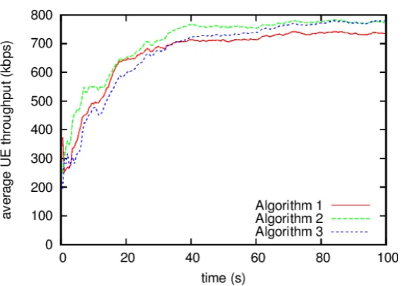
Simulation results are shown in Figure 3 and Figure 4.
Figure 3. Comparison of average UE throughput.
Figure 4. Load comparison of an example LTE cell and associated WLAN APs.
fore, the performance of the WLAN will decrease when it is in heavy load. At the same time, the resources in the LTE cell maybe have not been fully utilized.
Figure 3 also shows that at the beginning of the simulation, Algorithm 2 has a higher throughput than Algorithm 3. With the increase of time, the gap between them gets smaller and smaller. By the end of the simulation, the throughput of Algorithm 3 has exceeded a bit. It means that in the long term Algorithm 3 will have better performance, but it must spend more time to find out the optimized thresholds values.
evenly distributed between the LTE cell and the WLANs because of the greedy use of WLAN resources. Algorithm 2 can improve this situation by instructing part of the UEs to offload their traffic from WLAN to the LTE cell. However, the effect is limited and there are obvious load differences between the WLAN APs. The reason is that the same thresholds values will have different effects on APs in different locations, as explained in Figure 1. In contrast, Algorithm 3 can achieve load balancing by setting optimized thresholds values for each UE.
Figure 4 also reflects the difference of convergence speed between Algorithm 2 and 3. Because both of them adopt self-optimized scheme, they need some time to find out the optimized thresholds configuration. Algorithm 2 takes about 30 seconds to stabilize, while Algorithm 3 needs another 30 seconds.
5. Conclusion
In this paper, we studied the RAN-assisted WLAN offloading scheme and evalu-ated its performance by system simulation. Results show that this scheme can improve average UE throughput and gain better load balancing than traditional CN-based solutions. Furthermore, a performance comparison is illustrated be-tween the two kinds of control rules defined in RAN-assisted offloading and the simulation results reflect better property of the fine-grained mechanism.
We have not taken into account some control parameters such as WLAN backhaul rate in the proposed algorithms. Their impact on the system perform-ance will be studied in our future work.
Acknowledgements
This research is supported by National Science and Technology Major Project of the Ministry of Science and Technology of China (2014ZX03001025).
References
[1] 3GPP TS 23.261 (2010) IP Flow Mobility and Seamless Wireless Local Area Net-work (WLAN) Offload.
[2] 3GPP TS 23.861 (2009) Network Based IP Flow Mobility.
[3] Dae Sun, K., Yujin, N., Yoshinori, K. and Hidetoshi, Y. (2013) Efficient ANDSF- Assisted Wi-Fi Control for Mobile Data Offloading. Proc. Int. Conf. Wireless Communications and Mobile Computing, Cagliari, July 2013, 343-348.
[4] Nguyen, N. and Sato, T. (2014) A Proposal for Dynamic WLAN Selection for Mo-bile Data Offloading in Heterogeneous Network. Proc. IEEE Vehicular Technology Conference, Seoul, May 2014, 1-5.
[5] Chin-Yu, L., Fang-Yie, L., Jung-Chun, L., Castigiglione, A. and Palmieri, F. (2015) Heterogeneous Network Handover Using 3GPP ANDSF. Proc. Int. Conf. Advanced Information Networking and Applications, Gwangju, March 2015, 171-175.
[6] 3GPP TS 24.312 (2008) Access Network Discovery and Selection Function (ANDSF) Management Object (MO).
[7] 3GPP TR 37.834 (2014) Study on Wireless Local Area Network (WLAN)-3GPP Ra-dio Interworking.
Performance of SON for RSRP-Based LTE/WLAN Access Network Selection. Proc. Int. Symposium on Wireless Communications Systems, Barcelona, August 2014, 360-364.
[9] Irina, B., Daniela, L., Simone, R. and Andreas, L. (2015) RSRP-Based LTE-WLAN Traffic Steering. Proc. IEEE Vehcular Technology Conference, Glasgow, May 2015, 1-5.
[10] Wang, Y., Relja, D., Andreas, B., István, Z.K., Da- niela, L., Kathleen, S. and Bart, S. (2014) Performance of WLAN RSS-Based SON for LTE/WLAN Access Network Selection. Proc. Int. Symposium on Wireless Communications Systems, Barcelona, August 2014, 460-464. https://doi.org/10.1109/ISWCS.2014.6933397
[11] 3GPP TS 36.304 (2014) User Equipment (UE) Procedures in Idle Mode.
[12] 3GPP TR 36.814 (2010) Further Advancements for E-UTRA Physical Layer Aspects.
Submit or recommend next manuscript to SCIRP and we will provide best service for you:
Accepting pre-submission inquiries through Email, Facebook, LinkedIn, Twitter, etc. A wide selection of journals (inclusive of 9 subjects, more than 200 journals)
Providing 24-hour high-quality service User-friendly online submission system Fair and swift peer-review system
Efficient typesetting and proofreading procedure
Display of the result of downloads and visits, as well as the number of cited articles Maximum dissemination of your research work