1
Effect of prior laser microstructural refinement on the formation of amorphous layer in an
Al86Co7.6Ce6.4 alloy
C.L. Li1, J.W. Murray2, K.T. Voisey1,*, A.T. Clare2, D.G. McCartney1
1: Materials, Mechanics and Structures Research Division, Faculty of Engineering, The University of Nottingham, Nottingham NG7 2RD, UK.
2: Precision Manufacturing Centre, Faculty of Engineering, The University of Nottingham, Nottingham NG7 2RD, UK.
Contact: C.L. Li: [email protected], J.W. Murray: [email protected], K.T. Voisey (Corresponding author): [email protected], Tel.: +44 115 951 4139; Fax: +44 115 951 3600, Postal Address: Room A30a Coates, UniversityPark, Nottingham, NG7 2RD, UK, A.T. Clare: [email protected], D.G. McCartney:
Abstract
Laser surface melting (LSM) pre-treatment was conducted before large area electron beam
(LAEB) treatment in an attempt to eliminate the cracking of the amorphous layer. In our
previous work, LAEB treatment successfully generated an amorphous layer on a cast
polycrystalline Al-Co-Ce glass forming alloy. However, cracking was found and was associated
with large and brittle Al8Co2Ce phase in the bulk material. Results show that prior LSM
treatment in this present work can effectively refine the microstructure of as-cast material,
decreasing the particle size and particle spacing of Al8Co2Ce phase. This decrease in the
microstructural length scale greatly reduced the results of cracking of the amorphous layer. The
LAEB pulse number required for the homogenisation and amorphisation of treated layer was
also decreased for the laser pre-treated sample compared to as-cast material.
Keywords
electron beam, laser microstructural refinement, amorphous, glass-forming alloy,
2
1 Introduction
Amorphous metallic alloys are capable of exhibiting attractive mechanical and chemical
properties, especially corrosion resistance compared to the crystalline form of the same material.
The Al-TM (transition metal)-RE (rare earth) family of amorphous alloys is particularly
promising for corrosion resistant applications [1]. Due to their wide range of glass forming
compositions and tuneable corrosion resistance, Al-Co-Ce alloys have attracted attention from
corrosion protection engineers and scientists [2]. However, the high critical cooling rate required
to achieve the amorphous state limits the dimensions of bulk samples. Therefore, there is interest
in using surface modification techniques to generate amorphous coatings or films from these
alloys.
High intensity heat sources can rapidly heat and melt small, localised volumes of material, and
achieve cooling rates that are sufficiently high to suppress crystallisation and hence produce an
amorphous structure. For example, laser surface melting can produce cooling rates of ~ 105 K s-1
but electron beam surface melting can achieve even higher cooling rates, typically of the order of
108-109 K s-1 [3]. These processes have generated amorphous phases in various Al-, Zr- and Cu-
based alloys [4-6]. Large-area electron beam (LAEB) irradiation, a recent variant of electron
beam treatment, has several advantages such as a large beam size (~60 mm in diameter) which
decreases processing time by decreasing the need for overlapping tracks. It has been used to
polish mould surfaces [7], increase hardness and wear resistance [8], lower surface roughness,
reduce the porosity of sprayed coatings [9] and, as demonstrated in our previous paper [10],
generate an amorphous layer when used to melt the surface of a cast Al-Co-Ce alloy. However,
cracking of the amorphous layers was found to occur around large, pre-existing particles of the
3
has been applied on many alloys [11, 12]. The aim of the work reported here was to investigate
whether a prior laser surface treatment stage could refine the microstructure of as-cast Al-Co-Ce
alloy and eliminate the occurrence of this cracking.
2 Materials and methods
2.1 Materials
Bulk crystalline Al-Co-Ce alloy was cast under an argon atmosphere in an induction melting
furnace. The composition of the as-cast material was Al86.0Co7.6Ce6.4 (at.%) as determined
by inductively coupled plasma optical emission spectrometry (ICP-OES) carried out by the
Sheffield Assay Office (Sheffield, UK). The alloy composition is in the glass forming range for
this type of alloy [13]. 15 mm ×15 mm × 4 mm samples of the as-cast material were cut for laser
treatment, the surface was polished using 1 μm diamond paste. Following laser pre-treatment, a
raised zone was produced in the centre of each laser track due to surface tension effects. Laser
treated samples were then lightly polished again so that flat samples were exposed to the LAEB.
After polishing, laser treated material was finally cut into ~5 mm ×5 mm×4 mm pieces for the
LAEB treatment with different number of pulses.
2.2 Laser surface treatment
A YLR–2000SM ytterbium fibre laser (IPG laser, GmbH, Germany) with a wavelength of
1070 nm and a Gaussian (TEM00) beam profile was operated in the continuous wave mode at a
power of 2 kW throughout this work. A 600 µm diameter delivery fibre was used with a 192 mm
focal length lens, producing a focused spot size with a measured diameter of 952 µm. In order to
produce a useful larger beam diameter, the sample was positioned 5 mm below the focus,
4
used between successive passes. The samples were clamped onto a moveable stage and treated in
an argon atmosphere. Parameters for laser treatment are listed in Table 1.
Table 1 Parameters for laser microstructural refinement.
Distance from focus (mm) 5
Spot size in diameter (mm) 1.5
Sample traverse speed (mm·min-1) 6000
Overlap (% of track width) 20
2.3 Large area electron beam treatment
A PIKA electron beam surface finishing machine (PF32A) developed by Sodick, Japan was used
for LAEB treatment. The detailed information of this machine was described in Walker’s work
[14]. The electron beam has a diameter of approximately 60 mm. The pulse interval and pulse
duration of the electron beam are 11 s and 2-3 µs, respectively. Throughout this work cathode
voltage, anode voltage and solenoid voltage were kept constant at 35 kV, 5 kV and 1.5 kV,
respectively. Under the above working conditions, the electron beam has been reported to have
an energy density of approximately 6-10 J/cm2, varying with distance from the centre of the
electron beam [15]. Due to the small specimen size used in this study, the energy density on the
whole sample surfaces can be considered constant. The distance between the sample surface and
the electron beam source was approximately 300 mm. Before irradiation, the samples were fixed
in a clamp on the sample stage, with two sides in contact with the clamp and a ~10 mm gap
above the sample stage. Both as-cast and laser pre-treated samples were exposed to 8, 25 and 150
5
2.4 Microstructural characterisation
Before and after laser treatment, X-ray diffraction (XRD) was conducted using a Siemens D500
X-ray diffractometer (CuKα) with a step size of 0.02 ˚ and a time per step of 2 s. After electron
beam surface treatment, glancing angle XRD (GAXRD) was undertaken using a Bruker D8
Advance diffractometer (CuKα) was carried out to analyse the treated surface layer in isolation
from the bulk alloy. GAXRD patterns were collected with a step size of 0.02 ˚, a dwell time of
8 s per step and a 2 ˚ angle of incidence. AbsorbDX 1.1 software was used to calculate GAXRD
penetration depth. These calculations showed the, 90% contribution, X-ray penetration depth
varied with 2θ, ranging from 1.142 µm to 1.260 µm as 2θ varied from 15 ˚ to 50 ˚.
Sample surfaces and cross-sections were observed using a FEI XL30 scanning electron
microscope (SEM) using backscattered electrons (BSE) to form the image. The semi quantitative
composition of different phases was determined by energy dispersive X-ray spectroscopy (EDS).
Image analysis was performed using “Image J” software to characterise the laser track, including
width and thickness of the track as well as size and spacing of the refined phase. The length of
surface cracks were also measured using “Image J” based on four SEM images with
magnifications of 300×, each image covering an area of 970 µm by 730 µm. Measured cracks
had a minimum width of ~1.5 µm. The crack density was calculated through dividing the total
measured length of all surface cracks by the total image area analysed, thereby determining the
crack length per unit area. After measurements, the average value and standard derivation of
crack density were calculated. For track width and depth and size and spacing of the refined
phase, five measurements were conducted for each sample, again the results presented are the
6
3 Results
3.1 Microstructural characterisation of as-cast alloy
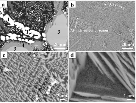
The as-cast Al-Co-Ce alloy is a multi-phase crystalline material containing four distinct phases
and a two phase eutectic (Figure 1a and Table 2) based on the microstructure observation and
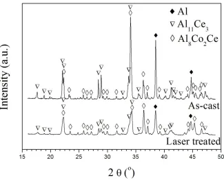
EDS analysis. XRD showed the presence of Al, Al11Ce3 and Al8Co2Ce (Figure 2). From a
combination of the EDS and XRD results, the bright white phase 1 is identified as Al11Ce3, the
darkest region 2 is the eutectic consisting of two phases attributed as Al and Al11Ce3. EDS results
are consistent with the large particles of phase 3 being Al8Co2Ce. Phase 5 is attributed to be
Al9Co2, although this phase is not evident from the XRD analysis. Phase 4 has a clearly distinct
contrast level, and hence different average atomic number, compared to both Al8Co2Ce and
phase 5. It is proposed that phase 4 is Al-rich Al8Co2Ce based on the similar atomic ratio of
7
Figure 1 SEM images of as-cast (a) and laser pre-treated sample (b). (c) and (d) are magnified local regions of the laser treated sample showing Al11Ce3 particles and Al-rich eutectic regions, respectively.
Table 2 EDS results of different phases in the as-cast material as shown in Figure 1.
Region Composition (at %) Probable phase
Al Co Ce
1 77.1 - 22.9 Primary Al11Ce3
2 97.4 - 2.6 Al/ Al11Ce3 eutectic
3 72.2 18.2 9.6 Al8Co2Ce
4 80.6 12.3 7.0 Al –rich Al8Co2Ce
8
Figure 2 XRD patterns of as-cast and laser pre-treated sample before large area electron beam treatment.
3.2 Microstructural characterisation following laser treatment of as-cast materials
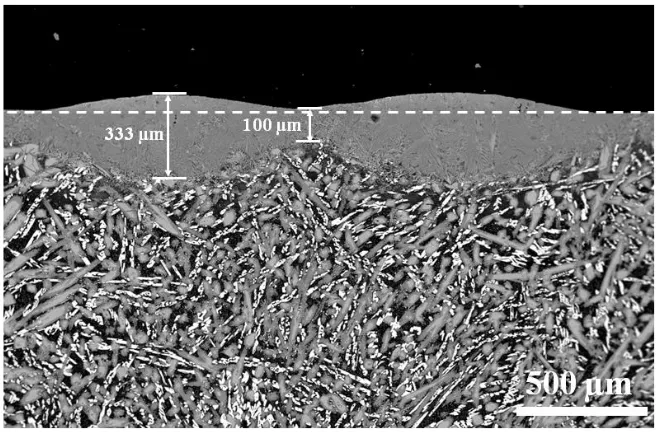
Figure 3 shows the cross section of laser pre-treated sample. It can be seen that laser treatment
produced a non-flat surface with ripples. These ripples above the dashed line as shown in Figure
3 were polished flat prior to LAEB treatment. After polishing, the sample still has at least
100 µm refined microstructure, which is far thicker than the possible LAEB treated layer
thickness (always less than 10 µm). Generally, laser tracks have a width of 1.4 mm, and a
maximum thickness of 333 µm. Compared with the untreated region, laser pre-treated region
exhibits an obviously refined microstructure with the disappearance of large Al8Co2Ce phase
9
Figure 3 Cross sectional SEM images of laser pre-treated sample. The ripples above the dashed line were polished flat before LAEB treatment.
Table 3 Characterisation of laser pre-treated sample, in each case the standard deviation of results is indicated.
Width of single track (mm) 1.4±0.1
Minimum thickness of laser track (µm) 100±15
Maximum thickness of laser track (µm) 333±27
Particle size of Al8Co2Ce phase in area (length and width, µm)
~20±5 ×
0.5±0.2
Particle spacing of neighbouring Al8Co2Ce phase (µm) ~0.2±0.1
Composition of Al/Al11Ce3 eutectic regions (at.%)
Al: 94.4 Co: 0.5 Ce: 5.1
Comparison of Figure 1a and b clearly shows that the microstructure of as-cast Al-Co-Ce alloy
was greatly refined, which is also seen in Figure 7. The initial as-cast material has large
Al8Co2Ce particles, approximately 100 µm × 20 µm in size. While, laser treatment produces a
highly refined structure with characteristic feature sizes of approximately 20 µm × 0.5 µm.
Accompanied with the decrease in particle size of Al8Co2Ce, the spacing between two
[image:9.612.67.435.360.555.2]10
approximately 30 µm, while laser pre-treatment reduced this value to approximately 0.2 µm. In
addition, for the sample subjected to laser pre-treatment, very few particles of primary Al11Ce3
phase were observed in the treated samples (Figure 1b and Figure 1c). Eutectic regions are also
found in laser pre-treated sample (Figure 1b and Figure 1d). Bright sub-micron lamellar phases
were seen distributed in the darker matrix, which is similar to that seen in the as-cast material, i.e.
bright Al11Ce3 phase distributed in a largely pure Al phase. The overall composition of this
eutectic region in the laser treated sample was analysed by EDS. Result shows a higher content
of Ce compared to that in the as-cast material (Table 2 and Table 3). It should also be noted that
laser pre-treatment completely eliminated the Al9Co2 phase present in the as- cast material.
Figure 2 also shows the XRD pattern of laser treated sample. It can be seen that the laser treated
sample still consists of three main phases, including Al, Al11Ce3 and Al8Co2Ce. However,
compared with the as-cast material, the amount of the Al11Ce3 phase was reduced by the laser
pre-treatment with the decreased ratio of the intensity of the strongest Al11Ce3 peak (2=34 ˚) to
that of the Al8Co2Ce phase (2=36.5 ˚). The Al11Ce3 peaks in XRD result and Ce element in EDS
result of laser pre-treated sample also confirm those eutectic regions are composed of Al and
Al11Ce3 phase.
3.3 Microstructural characterisation following LAEB of as-cast and laser pre-treated
materials
3.3.1 Glancing angle XRD results
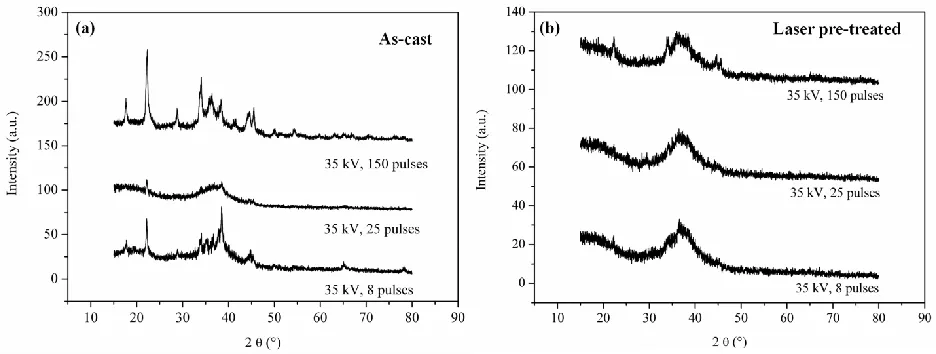
Figure 4 shows the glancing angle XRD results of LAEB treated layer with different initial
microstructures. Obvious crystalline peaks are seen in the GAXRD spectra of all samples that
11
peaks have decreased in intensity and an amorphous hump is present at 2 37o. After 150
pulses the crystalline peaks have reappeared and the amorphous hump is no longer discernable.
There are markedly fewer crystalline peaks in the GAXRD spectra of treated samples with laser
pre-treatment (Figure 4b). Those peaks that are present are significantly smaller than those in
Figure 4 and an amorphous hump is seen at 2 37o. Several small crystalline peaks can be seen
[image:11.612.73.541.248.425.2]in the GAXRD spectrum of sample which underwent laser pre-treatment and 150 LAEB pulses.
Figure 4 GAXRD spectra of LAEB treated layers with different initial microstructures: (a) as cast and (b) laser treated.
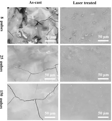
3.3.2 Surface morphology
Figure 5 shows the surface morphology of LAEB treated samples with different initial
microstructures. For the samples without any laser pre-treatment, the LAEB remelted surface
layer is still markedly heterogeneous after 8 pulses. With increasing numbers of pulses, this layer
gradually becomes homogeneous. For the laser pre-treated samples, the remelted layer generally
also becomes more uniform in composition with increasing number of pulses. However, it can be
seen that this homogenisation is more rapid in the laser pre-treated sample. The composition of
12
scale over which heterogeneities exist is decreased for the refined microstructures compared to
the as-cast material after the same number pulses of LAEB irradiation.
As seen in Figure 5, small, round white particles were observed on the surface of all samples
after LAEB treatment. Fewer, larger particles were seen on LAEB treated as-cast material,
whereas a higher number of smaller particles were seen for laser pre-treated material. Full
investigation of the native of these particles does not form part of the current work but will be
[image:12.612.79.438.276.663.2]considered in our future work.
13
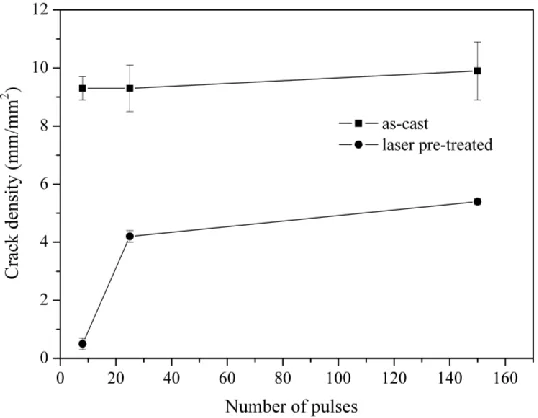
For the laser pre-treated sample, the extent of LAEB induced cracking was notably less
compared to the as-cast material (Figure 5 and Figure 6). For both type of samples, the extent of
cracking increased with the number of pulses. However, for the laser pre-treated sample, the
majority of cracking was generated within the first 25 pulses, accompanied by a small increase in
the crack density with increasing the number of pulses from 25 to 150. However, in the case of
[image:13.612.76.345.246.455.2]the as-cast material, the majority of cracking formed within the first 8 pulses.
Figure 6 Crack density of treated layers as a function of the number of LAEB pulses.
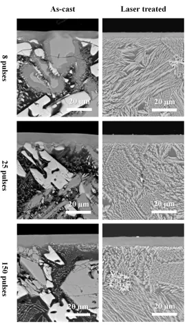
3.3.3 Cross sectional morphology
Figure 7 shows the cross sections of LAEB treated samples with as-cast and laser pre-treated
initial microstructure. For both sample types, there is some variation in the thickness of the
treated layer, this is most apparent for the as-cast samples where the thickness of the treated layer
varies with the underlying crystalline phase type (Figure 7). In the as-cast samples the treated
layer was thinner in regions above Al11Ce3 and Al8Co2Ce phases compared to regions above the
eutectic, particularly for the 8 pulse sample. The fluctuation of the thickness of the treated layer
14
structure, resulting in a more regular, straighter interface between the treated layer and bulk
material. The homogeneity of the treated layer is increased both by laser microstructural
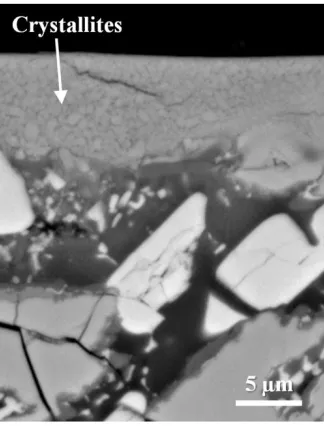
refinement and increasing the number of LAEB pulses. Small crystallites were found in localised
regions of the as-cast sample treated with 150 pulses (Figure 8), this is consistent with the XRD
results in Figure 4. Such crystallites were not visible in the laser pre-treated sample after the
15
16
Figure 8 Cross section of LAEB treated as-cast material (35 kV, 150 pulses).
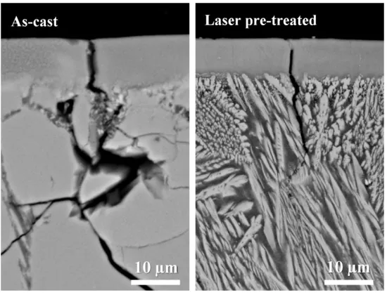
Figure 9 shows the localised cross sectional morphologies of LAEB treated samples (35 kV, 150
pulses) with different initial microstructures. Cracks can be seen in both samples. When the
LAEB irradiation was applied to the as-cast material, the crack propagated in the large Al8Co2Ce
phases over the distance of up to ~70 µm. However, in the case of laser pre-treated sample, the
cracking stopped in the depth of ~20 µm, which is much shorter than that in the LAEB treated
as-cast sample. In addition, the crack in the laser pre-treated sample after LAEB treatment was
17
Figure 9 Localised cross sectional morphologies showing the cracks in the LAEB treated samples with different initial microstructures (35 kV, 150 pulses).
4 Discussion
4.1 Microstructual refinement of Al-Co-Ce alloy by the laser pre-treatment
Laser surface melting melts a thin layer of material; this then rapidly cools and solidifies as heat
is conducted away by the rest of the material, generating a refined microstructure. The
microstructural refinement of the as-cast material was mainly shown by the decrease of particle
size and particle spacing of the Al8Co2Ce phase. The proportions of the phases present have also
been altered by laser treatment due to the high solidification speeds inducing non-equilibrium
microstructures, in this case decreasing the amount of primary Al11Ce3. The rapid solidification
also changed the composition of the Al-rich eutectic region by increasing the content of Ce in the
Al-rich region, and eliminated the Al9Co2 phase.
4.2 Effect of laser microstructual refinement on the amorphisation of Al-Co-Ce alloy layer
Generally, there are two necessary conditions for the amorphisation of Al-Co-Ce alloy in LAEB
18
the glass forming composition. This needs a sufficiently high temperature and enough time for
the melting and diffusion. Therefore, when low cathode voltage or small number of pulses was
used, the alloy cannot be transformed to amorphous state [10]. Second, upon obtaining a
homogeneous composition, a fast enough cooling rate is a crucial condition for the alloy to form
amorphous phase. The cooling rate following laser surface melting was sufficiently high to refine
the microstructure of Al-Co-Ce alloy, but not to generate the amorphous layer. However, LAEB
can produce cooling rates that are orders of magnitude larger, typically 108-109 K s-1[3], these
are high enough to enable the amorphous state to be achieved.
For the as-cast material, 8 pulses irradiation provides insufficient time for the molten layer to
achieve a uniform composition. However, 25 pulses produces more extensive homogenisation.
Therefore, the alloy was amorphised after 25 pulses of irradiation, but not after 8 pulses. In the
case of laser treated sample, the alloy microstructure was greatly refined. The time, and hence
number of pulses, required for homogenisation, and hence amorphisation of the surface layer,
decreases by the decreased particle size, particle spacing of the Al8Co2Ce phase. The decreased
time required for microstructural homogenisation and amorphisation also reduced the danger of
significant bulk sample pre-heating which could affect cooling rate and potentially make
amorphisation less likely. Therefore, more extensive homogenisation, and amorphisation, is seen
for fewer pulses in the laser refined material. In this present work, the alloy was greatly
homogenised and amorphised after only 8 pulses (Figure 5).
The reappearance of crystalline peaks in 150 pulses irradiated as-cast and laser treated material
was seen in the glancing angle XRD results. The crystallisation may result from reduced cooling
rates due to progressive temperature increase of the substrate with additional pulses [10].
19
material (Figure 8) but not in that of laser treated material after the same electron beam
irradiation. However, it should be noted that the absence of visible crystalline phases in the SEM
image of the latter material may simply be due to a very small, sub-micron, crystal size.
4.3 Effect of laser microstructual refinement on the cracking control of Al-Co-Ce
amorphous layer
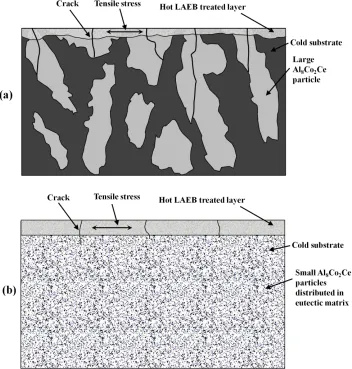
Figure 10a shows a schematic diagram of the cracking in the LAEB treated as-cast material. The
LAEB surface treatment generates a thermal gradient in the material. After solidification, the hot
treated layer contracts more than the cold underlying substrate. A tensile stress is generated in
the surface, and near surface material, due to this differential contraction. If this tensile stress
exceeds the fracture strength of any material in the near surface area then that material will crack.
LAEB treatment of as-cast Al-Co-Ce alloy showed that cracking was correlated with the
existence of large Al8Co2Ce phase particles. This is due to the brittleness characteristic of this
phase [10]. These large and brittle Al8Co2Ce phase particles act as easy crack initiation sites in
the as-cast material, these particles also provide easy growth paths for the crack propagation, as
shown in Figure 9a.
Figure 10b shows the cracking in the laser treated sample after LAEB irradiation. Laser
pre-treatment has eliminated the easy crack initiation sites and crack growth paths i.e.
microstructural refinement has prevented the formation of large Al8Co2Ce phase particles. Hence
cracking becomes less likely and the few cracks that do form are shorter and terminate rapidly in
20
It should also be noted that the as-cast material contains a number of different phases which will
have different coefficients of thermal expansion. Stresses arising from differential thermal
[image:20.612.80.432.197.566.2]expansion will contribute to crack generation.
Figure 10 Schematic diagram of cracking in different LAEB treated samples: (a) as-cast sample and (b) laser microstructural refined sample.
4.4 Future work
21
microstructural refinement and amorphisation could be carried out by LAEB treatment.
Investigation of residual stresses in the treated layer is also of interest, this would be of particular relevance for the generation of thicker treated layers.
5 Conclusions
The microstructure of the as-cast Al86.0Co7.6Ce6.4 (at.%) alloy was successfully refined by
laser pre-treatment. The particle size and spacing of the Al8Co2Ce phase are decreased.
The refined microstructure decreased the number of LAEB pulses required for the
homogenisation and amorphisation of Al-Co-Ce alloy.
Prior laser microstructural refinement successfully decreased the extent of cracking of the
amorphous surface layer following LAEB.
The suppressed cracking of laser pre-treated LAEB treated Al-Co-Ce amorphous layer was
due to the removal of large, brittle, Al8Co2Ce phase particles.
References
[1] A.M. Lucente, J.R. Scully, Localized corrosion of Al-based amorphous-nanocrystalline alloys with solute-lean nanocrystals: Pit stabilization, Journal of the Electrochemical Society, 155 (2008) C234-C243. [2] N. Tailleart, B. Gauthier, S. Eidelman, J.R. Scully, Metallurgical and Physical Factors Controlling the Multi-Functional Corrosion Properties of Pulsed Thermal-Sprayed Al-Co-Ce Coatings, Corrosion, 68 (2012) 035006.
[3] Y. Qin, J. Zou, C. Dong, X. Wang, A. Wu, Y. Liu, S. Hao, Q. Guan, Temperature–stress fields and related phenomena induced by a high current pulsed electron beam, Nucl Instrum Meth B, 225 (2004) 544-554.
[4] J.G. Hoekstra, S.B. Qadri, J.R. Scully, J.M. Fitz-Gerald, Laser surface modification of a crystalline Al-Co-Ce alloy for enhanced corrosion resistance, Adv Eng Mater, 7 (2005) 805-809.
[5] J. Do, C. Jeon, D.-H. Nam, C. Kim, Y. Song, S. Lee, Correlation of Microstructure and Ballistic Performance of Multilayered Zr-based Amorphous Surface Composites Fabricated by High-Energy Electron-Beam Irradiation, Metall Mater Trans A, 42 (2011) 1191-1204.
[6] K. Lee, E. Yun, S. Lee, N.J. Kim, Fabrication of Zr-and Cu-base bulk metallic glass/Cu surface composites by high-energy electron-beam irradiation, Mater Sci Eng A-Struct, 408 (2005) 92-101. [7] A. Okada, Y. Uno, H. Watanabe, K. Fujiwara, Surface modification of stainless steel for surgical tool by EB-Polishing, Key Eng Mater, 407 (2009) 339-342.
[8] T. Grosdidier, J. Zou, B. Bolle, S. Hao, C. Dong, Grain refinement, hardening and metastable phase formation by high current pulsed electron beam (HCPEB) treatment under heating and melting modes, J Alloy Compd, 504 (2010) S508-S511.
22
[10] C.L. Li, J.W. Murray, K.T. Voisey, A.T. Clare, D.G. McCartney, Amorphous layer formation in Al86.0Co7.6Ce6.4 glass-forming alloy by large-area electron beam irradiation, Appl Surf Sci, 280 (2013) 431-438.
[11] C. Kwakernaak, W.G. Sloof, T.J. Nijdam, Microstructure refinement of NiCoCrAIY alloys by laser surface melting, Metall Mater Trans A, 37 (2006) 695-703.
[12] F.A. España, V.K. Balla, A. Bandyopadhyay, Laser processing of bulk Al–12Si alloy: influence of microstructure on thermal properties, Philos Mag, 91 (2011) 574-588.
[13] M.C. Gao, N. Ünlü, M. Mihalkovic, M. Widom, G. Shiflet, Glass formation, phase equilibria, and thermodynamic assessment of the Al-Ce-Co system assisted by first-principles energy calculations, Metall Mater Trans A, 38 (2007) 2540-2551.
[14] J.C. Walker, J. Murray, S. Narania, A.T. Clare, Dry Sliding Friction and Wear Behaviour of an Electron Beam Melted Hypereutectic Al–Si Alloy, Tribol Lett, (2011) 1-10.
[15] Y. Uno, A. Okada, K. Uemura, P. Raharjo, T. Furukawa, K. Karato, High-efficiency finishing process for metal mold by large-area electron beam irradiation, Precis Eng, 29 (2005) 449-455.
Figure captions
Figure 1 SEM images of as-cast (a) and laser pre-treated sample (b). (c) and (d) are magnified local
regions of the laser treated sample showing Al11Ce3 particles and Al-rich eutectic regions, respectively.
Figure 2 XRD patterns of as-cast and laser pre-treated sample before large area electron beam treatment.
Figure 3 Cross sectional SEM images of laser pre-treated sample. The ripples above the dashed line were
polished flat before LAEB treatment.
Figure 4 GAXRD spectra of LAEB treated layers with different initial microstructures.
Figure 5 BSE images showing plan views of electron beam treated samples with different initial
microstructures and number of LAEB pulses.
Figure 6 Crack density of treated layers as a function of the number of LAEB pulses.
Figure 7 Cross sectional morphology (back scattered electron SEM images) of electron beam treated
samples with different initial microstructures and number of LAEB pulses.
Figure 8 Cross section of LAEB treated as-cast material (35 kV, 150 pulses).
Figure 9 Localised cross sectional morphologies showing the cracks in the LAEB treated samples with
different initial microstructures (35 kV, 150 pulses).
Figure 10 Schematic diagram of cracking in different LAEB treated samples: (a) as-cast sample and (b)
23
Table captions
Table 4 Parameters for laser microstructural refinement.
Table 5 EDS results of different phases in the as-cast material as shown in Figure 1.