Abstract— Compressed air vehicle (CAV) is a vehicle driven by compressed air which is stored in a tank at 8-10 bar pressure and a capacity of 60 litres. The major components of CAV are pneumatic double acting actuator,5/3 solenoid valve, compressor tank, pressure gauge, limit switch, contact breaker,24 volts battery supply, V belt drive, non-return valve, pillow block bearing, crank. Initially, the tank is filled with compressed air using an air compressor up-to 8-10 bar through a non- return valve placed at the inlet, relief valve is used to drain out the excessive air from the tank, the air from the tank is supplied to the double acting pneumatic actuator through solenoid valve from one side due to which forward stroke takes place, at the end of forward stroke the actuator makes contact with the limit switch and hence reverses the supply of air from other side of the piston using contact breaker and therefore the retraction stroke takes place. The electronic components such as the limit switch, contact breakers, solenoid valve are operated by a 24 volt battery setup all connected in series. Due to the forward and retraction stroke the crank converts the linear motion of the actuator to the rotary motion of the shaft, this is directly coupled with axle of the rear wheel using a V -belt drive mechanism. Hence the movement of the vehicle is achieved.
Index Terms— Double acting actuator, 5/3 solenoid valve, limit switch, contact breaker.
1) INTRODUCTION
The first compressed air vehicle was built up in France by a Polish designer Louis Mekarski in 1870. It was protected in 1872 and 1873 and was tried in Paris in 1876. The working guideline of Mekarski's motor was the utilization of vitality put away in compacted air to build gas enthalpy of high temperature water when it is gone through heated water.
Another utilization of the compressed air to drive vehicles originates from Uruguay in 1984, where Armando Regusci has been engaged with developing these machines. He built a four-wheeler with pneumatic motor which voyaged 100 km on a solitary tank in 1992. The Air Car was produced by Luxembourg-based MDI Group originator and previous Formula One designer Guy Negre is which chips away at compacted air motor (CAE).
He created compressed air-4-barrels motor keep running on air and fuel in 1998 which he claims to be zero contamination autos. It utilizes compacted air to push its cylinders when running at speeds under 35 mph and at higher rates of 96 mph, the packed air was warmed by a fuel (bio fuel, gas, or diesel), due to which the air extended before
entering the motor. A fuel proficiency of around 100 mpg was watched. Light weight vehicles are the following progression in the advancement of cars. Diminishing the heaviness of the vehicle has numerous preferences as it expands the general proficiency of the vehicle, helps in enhancing mobility, requires less vitality to stop and run the vehicle. The most recent looks into are going ahead around the globe keeping in mind the end goal to concoct creative thoughts. In any case, a dangerous atmospheric deviation is likewise one of the issues which is influencing the man. The temperature of the earth is expanding radically and this thusly is causing climatic changes. The petroleum products are generally utilized as a wellspring of vitality in different diverse fields like power plants, inner and outside burning motors, as warmth source in assembling businesses and so forth. Be that as it may, its stock is exceptionally constrained and because of this enormous utilize, petroleum products are lessening at quicker rate. Along these lines, in this universe of vitality emergency, it is important to create elective innovations to utilize sustainable power sources, so non-renewable energy sources can be saved. One of the real wellspring of the contamination is the smoke turning out from the vehicles. So an elective method for delivering the running the vehicle must be made so we can anticipate additionally harm to the earth. The elective wellsprings of vitality accessible are sunlight based, electric, air and so on.
Air acts like a cover for the earth. It is the blend of gasses, which makes it impartial and non-dirtying. It has the property to get compacted to a very high weight and hold it for a drawn out stretch of time. Real favorable position of utilizing compacted motor is that an unadulterated packed air vehicle delivers no contamination at the tailpipe.
Compacted air innovation diminishes the cost of vehicle generation by around 20%, in light of the fact that there is no compelling reason to manufacture a cooling framework, fuel tank, Ignition Systems or silencers.
2) LITERATURE REVIEW
For reasonable application to transportation, a few specialized issues must be first tended to:
As the pressurized air grows, it is cooled, which restrains the productivity (joined gas law). This cooling diminishes the measure of vitality that can be recuperated by extension, so functional engines apply surrounding warmth to expand the development accessible. Conversely, the pressure of the air by pumps (to pressurize the tanks) will warm the air. On the off chance that this warmth isn't recouped it speaks to a further loss of vitality thus lessens productivity. Storage of air Devadiga Aakash Ashok1, K.P Rahul Machaiah2, Mufeed I Shareef3, Narasimha Murthy B.M4,
K V Suresh5
1,2,3,4
UG Students, Department of Mechanical Engineering,
5 Professor, Department of Mechanical Engineering, Alva’s Institute of Engineering and Technology, Mangalore, Karnataka.
DESIGN AND FABRICATION OF
COMPRESSED AIR POWERED VEHICLE
at high weight requires solid holders, which if not made of extraordinary materials will be substantial, diminishing vehicle proficiency, while colorful materials, (for example, carbon fiber composites) have a tendency to be costly.
Energy recuperation in a vehicle amid braking by compressing air additionally produces warm, which must be saved for proficiency. It ought to be noticed that the air engine isn't genuinely discharge free, since the ability to compress the air at first as a rule includes emanations at the purpose of age.
Frenchmen Andraud and Tessie in the first place recorded compacted air vehicle in France in 1838. An auto kept running on a test track at Chailloton the ninth July 1840, and functioned admirably, yet the thought was not sought after further.
Łukasz Szabłowskia exhibited dynamic investigation of the packed air vitality stockpiling in the auto. The investigation was utilized to decide those procedures most pertinent to accomplishing most noteworthy conceivable productivity. He thought about after procedures
1. Filling a tank with compacted air, including cooling.
2. Straightforward tank releasing through a turbine working at steady weight.
3. Releasing the tank utilizing air warming of the working medium between two turbines working at steady weights. He found because of pressure incorporating cooling in all cases around 59 kg of air has been directed into the tank because of the expected last temperature of the procedure – 99◦C.
Air auto is an auto as of now being produced which is still in the R&D arrange everywhere throughout the world. The fundamental rule engaged with this idea is that packed air is sufficiently proficient to give adequate push that thusly can impel the auto. It isn't just eco-accommodating, contamination free, but at the same time is extremely prudent.
This tends to both the issues of fuel emergency and contamination. Exploratory investigation were done on this adjusted motor to discover its execution attributes like brake control, mechanical productivity, demonstrated power, torque and so forth. It was noticed that weight higher than that right now utilized brought about expanded motor execution as far as yield power, torque and speed. Their investigations displays the air in can be utilized as a part of vehicles as the fundamental or helper wellspring of energy framework.
Test examination were completed on this changed motor to discover its execution qualities like brake control, mechanical productivity, demonstrated power, torque and so on. The execution can be enhanced by expanding delta weight, lessening the vehicle weight and so forth. Upkeep of this is exceptionally immaterial contrasted with ordinary I.C.
Motors. Packed air motor is demonstrated to give beginning torque and comparable properties to I.C. Motor. Cost of this framework is to a great degree low when contrasted and Electrical Vehicles, Conventional I.C. Motors and other Hybrid Systems. Results demonstrated that the contamination and fuel utilization of the interior burning motor vehicles can be limited by the utilization of the pneumatic half breed vehicles. The examination was utilized to decide those procedures most applicable to accomplishing most noteworthy conceivable proficiency. Current four strokes single barrel motor (bicycles/moped) can be keep running on the compacted air with a couple of adjustments
that are the fundamental destinations of the investigation. A portion of these articles speaks to the essential component of compressed air motor set up with specialized information.
3) WORKING
The framework of the compressed air vehicle is done by welding process in which the boxed shape mild steel hollow rods are used to make the framework and then the brackets are welded in order to mount the components on the frame.
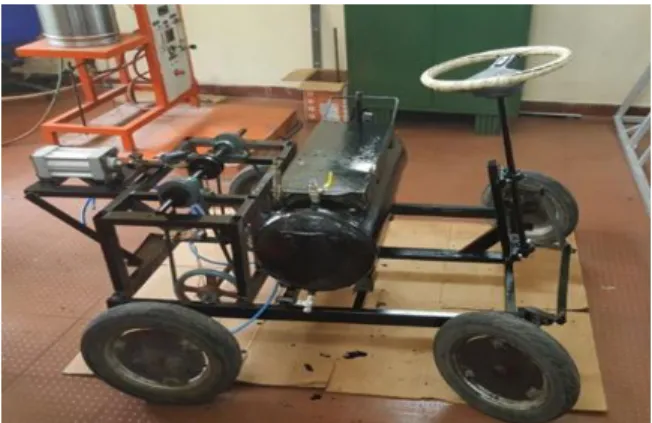
The tank is filled with compressed air using an air compressor up-to 8-10 bar through a non- return valve placed at the inlet, relief valve is used to drain out the excessive air from the tank, the relief valve is also set to open at a predetermined set pressure to protect the tank and other equipment from being subjected to pressure that exceed design limit. Pressure gauge is placed in order to measure the pressure inside the storage tank. The air from the tank is supplied to the double acting pneumatic actuator through solenoid valve from one side due to which forward stroke takes place, at the end of forward stroke the actuator makes contact with the limit switch and hence reverses the supply of air from other side of the piston using contact breaker and therefore the retraction stroke takes place. In the forward stroke when the air is supplied to the actuator the piston in the actuator moves forward which is coupled with the crank assembly which converts the linear motion of piston into rotary motion. The crank assembly is directly coupled with v belt drive which transmit the power from crank assembly to the shaft to which the wheels are connected. Hence due to which the movement of the vehicle is achieved. The vehicle runs for about 0.6 to 0.8 km for the pressure stored in the tank at 8-10 bars.
Figure 1. Compressed air vehicle
The electronic components such as the limit switch, contact breakers, solenoid valve are operated by a 24 volt battery setup all connected in series. Due to the forward and retraction stroke the crank converts the linear motion of the actuator to the rotary motion of the shaft, this is directly coupled with axle of the rear wheel using a V -belt drive mechanism. Hence the movement of the vehicle is achieved.
These electronic components are linked with other using copper wire which is turn connected to the battery supply which are placed in series. The solenoid valve is connected to the pneumatic double acting actuator using pneumatic pipes through which the compressed air is passed to carry out the operation.
Figure 2. Drive Mechanism
4) COMPONENTS
The major components used in this compressed air vehicle are,
Pneumatic double acting Actuator:
Pneumatic double acting actuator is a device which coverts energy in the form of compressed air to the mechanical motion. When the compressed it is passed from the storage tank to the actuator using a solenoid the piston moves forward and backward. When the piston reaches extreme position it comes in contact with the limit switch placed at the end as the limit switch strikes and move forward the contact breaker breaks the circuit and using the solenoid valve reverses the direction of the flow of the compressed air and hence the piston retracts. This actuator is coupled with the crank which helps to convert linear motion of the piston into rotary motion of the crank which is further coupled with rear shaft using belt drive mechanism.
Figure 3. Pneumatic double acting actuator
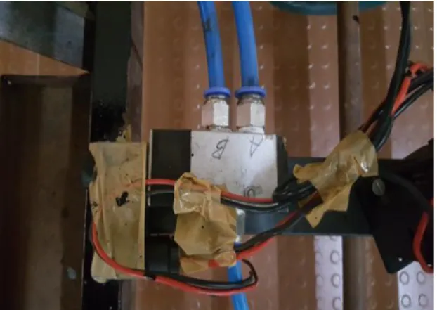
5/3 Solenoid Valve:
A solenoid valve is an electromechanically operated valve. The valve is controlled by an electric current through solenoid. Solenoid offers fast and safe switching, high reliability, long service life, good medium compatibility of the material used, low control power and compact design. It works on the principle of difference in the pressure at the inlet and outlet. It is basically a direction control valve which direct the flow of compressed air from any source input to different outputs. It is operated using a 24 volts battery supply using a contact breaker in order to change the direction of the compressed air.
Figure 4. 5/3 Solenoid valve
Limit Switch:
A limit switch is an electromechanical device that consists of an actuator mechanically linked to a set of contacts. When an object comes into contact with the actuator, the device operates the contacts to make or break an electrical connection.When the compressed air is passed from the tank through the solenoid valve the double acting actuator is made to work in the forward direction as it reaches the maximum point its comes in contact with the limit switch which moves forward an as the solenoid valve retracts it changes the direction of flow of compressed air and makes the piston of the actuator to move in other opposite direction.
Figure 5. Limit switch
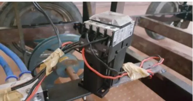
Contact Breaker:
It is a typical type of electrical switch, and the term typically refers to the switching device found in the distributor. The purpose of the contact breaker is to interrupt the current flowing in the primary winding, when this occurs the collapsing current induces a high voltage in the secondary winding of the coil. It is basically helps to break the circuit when the piston of the actuator comes in contact with the limit switch. The contact breaker breaks the circuit and makes the solenoid to allow the compressed air to flow in the other direction. Hence the retraction motion of the piston is achieved in the double acting actuator. It is typically used in order to break the forward circuit and allow the flow of compressed air in reverse direction. It works on 24 volt battery supply connected in series connection
Figure 6. Contact breaker
5) CALCULATIONS Pneumatic Actuator:
Let the pressure filled in tank normally be 8 bar = 0.8 N/mm2 p = internal pressure= 8 kg/cm2 = 0.8 N/mm2,
d = diameter of cylinder=80 mm selected, Force Output = Pressure × Area
F = P X A F = 0.8 x π r2 F = 0.8x π 402 F = 4021.238 N.
F= 409.9 kg
This is the force (F) generated by the cylinder.
We know torque on shaft = F x r T = 4021.238 x 25
T = 100530.95 N-mm T=100.530 N-m P=2πNT/60
P = (2 x 3.142 x 200 x 100.53)/ 60 P = 2105.768 W
P = 2.105 kW
This is the torque (T) generated at crank.
Pulley:
Now pulley of 100 mm and 200 mm Ratio 2
T1= T x 2 = 201.0619 N-m
T1- Torque at larger pulley T2- Torque at smaller pulley
Diameter of tyre = 300 mm T1= F x 150
F = 201061.9/150 = 1340.41 N = 136.63 kg This is the force generated at wheel.
Design of Crank rotating shaft:
T= 3.14/16 x fs x d3 100530= 3.14/16 x 135 x d3 d = 15.59mm
By using 20mm shaft, the shaft design is safe.
For 20mm Shaft diameter standard bearing no. P204 is used.
Design of wheel rotating shaft under combine twisting and bending moment:
W=100 kg= 100 x 9.8 = 981 N say M= F x L
M= 981x100=98100 N-mm T1= 125650 N-mm
Te= √ (M2+T2) = √981002+1256502
Te=159.409 N-m
Te=π/16 x σs x d3
D3=159409.95x16/π x 135 d=3√6013.3=18.18 mm d=19mm
shaft of diameter(d) 20mm used for safer design.
.
Calculation of length of belt:
We know that radius of pulley on shaft R1 = d1/2 = 200 /2 = 100mm Radius of pulley on motor shaft R2 = d2/2 = 100/2 = 50 mm
Center distance between two pulley, X = 420mm We know length of belt
L = П (r2+r1) + 2 X + (r2-r1)2/X
L = П (100 + 50) + (2 x420) + (100 – 50)2/420 L = 1317 mm = 1.3 m.
6) RESULTS AND DISCUSSION The graph for following parameters were plotted:
1) Pressure 2) Distance 3) Time
Figure 7. Pressure v/s Distance
Figure 7 shows the graphical representation of pressure vs distance with load. From this graph it can be noted that the distance covered by vehicle decreases with the decrease in stored pressure of air tank. In order to increase the distance travelled the air should be stored at higher pressure.
Figure 8. Pressure v/s Time
Figure 8 shows the graphical representation of pressure vs time with load. In this graph as the time increases the consumption of the air increases and pressure of the tank
decreases simultaneously. Hence in order to obtain long duration of run the vehicle should be stored with the compressed air at higher pressure.
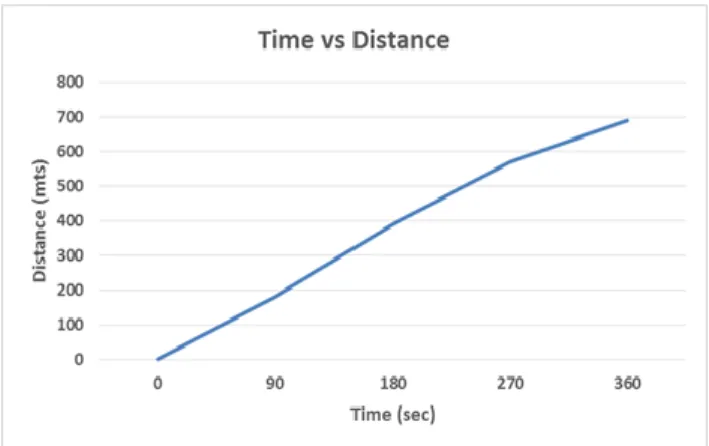
Figure 9. Time v/s Distance
Figure 9 shows the graphical representation of time vs distance with load. The graph shows almost a linear relationship between distance and time. Hence with time the distance also relatively increases. Hence the vehicle moves continuously for certain time until the stored air gets exhausted. Here for the full tank at 8 bar the total distance covered is 800m in 360 seconds.
7) CONCLUSION
As the pollution is increasing with time, the methods for transportation likewise assumes a critical part for this commitment. Air pollution is a critical part which is to be controlled, as the IC engine frees exhaust gases which is exceptionally destructive and furthermore non-renewable energy sources are getting drained. Keeping in mind the end goal to beat this issue compressed air vehicle brings leverage over it. It's critical to recollect that while vehicles running on just compressed air may appear like an inaccessible dream, yet despite everything they have open enthusiasm because of their ecological amicable nature. Compressed air for vehicle drive is as of now being investigated and now air controlled vehicles are being produced as a more environmental friendly methods for transportation. The Air Powered vehicle innovation is less expensive. Rather, It's boundless utilize will help humankind in controlling the major issue of a worldwide temperature alteration.
REFERENCES
[1] Rixon K L, Mohammed Shareef V, Prajith K S, Sarath K, Sreejith S, Sreeraj P Department of Mechanical Engineering, Nehru College of Engineering and Research Centre, Pampady, Thiruvilwamala, Trissur District, Kerala published ―Fabrication of Compressed Air Bike‖
International Research Journal of Engineering and Technology (IRJET) Volume: 03 Issue: 03, Mar-2016, e-ISSN: 2395 -0056, p-ISSN: 2395-0072.
[2] Kripal Raj Mishra, Gaurav Sugandh, Anurag Bahuguna , Rajesh Pant of Department Of Mechanical Engineering from Tula’s institute of Engineering
&Technology, Dehra Dun, India, published ―Study About Engine Operated By Compressed Air (C.A.E): A Pneumatic Power Source‖ IOSR Journal of Mechanical and Civil Engineering (IOSR-JMCE) Volume 11, Issue 6 Ver.
IV (Nov- Dec. 2014), e-ISSN: 2278-1684,p-ISSN: 2320-334X.
[3] Singh B.R. and Singh Onkar, 2008, Energy storage system to meet the challenges of 21st century- An over view- On all India seminar on energy management in perceptive of Indian scenario-held on October17-19, 2008 at Institution of Engineer (India), State Centre, Engineer's Bhawan, Lucknow-ProceedingsChapter15, pp 157-167.
[4] Mistry Manish K., Dr. Pravin P. Rathod, Prof. Sorathiya Arvind S.,
―study and development of compressed air engine single cylinder’’.
IJAET/Vol.III/ Issue I/January-March, 2012/271-274.
[5] Ankit Sharma &Manpreet Singh of Department of Mechanical Engineering from Lovely Professional University, Jalandhar, India published ― Parametric Analysis Of Air Driven Engine: A critical review‖
International Journal Of Advanced Research in Engineering And Technology(IJARET), VOLUME 6, Issue 4, April (2015), p-ISSN:
0976-6480, e-ISSN: 0976-6499.
[6] Rohamare R, Dhage Amit A, Dhage Amit A and Tambe Kiran B of Shri Sai Baba Institute of Engineering Research & Allied Sciences, Tal- Rahata, Ahmednagar (Maharashtra) published ―Conversion of 4-Stroke Single Cylinder Petrol Engine into Compressed Air Engine‖, International Journal of Informative & Futuristic Research (IJIFR), Volume 2, Issue 2, October 2014, ISSN (Online): 2347-1697.
[7] Mr. B. Ramanjan eyulu, J. Tarun Kumar, G. Praveen Kumar - Design and Fabrication of Compressed Air Vehicle – International Journal Paper- ISSN NO : 2348-4845
Prof. K V Suresh, Professor
Department of Mechanical Engineering, Alva’s Institute of Engineering and Technology [email protected]
Mr. Devadiga Aakash Ashok, Final year B.E Student,
Department of Mechanical Engineering, Alva’s Institute of Engineering and Technology [email protected]
Mr. K P Rahul Machaiah, Final year B.E student,
Department of Mechanical Engineering, Alva’s Institute of Engineering and Technology [email protected]
Mr. Mufeed I Shareef, Final year B.E Student,
Department of Mechanical Engineering, Alva’s Institute of Engineering and Technology [email protected]
Mr. Narasimha Murthy B.M, Final year B.E student,
Department of Mechanical Engineering, Alva’s Institute of Engineering and Technology [email protected]