amdahl
®
amdahl'"
AMDAHL 470
Computing Systems
Physical Planning Manual
REVISION NOTICE
This is the fourth edition. This revision adds information about PDU (MOD V) and Extended Channels feature (dual Channel Units). Also, raised-floor tile cutout dimensions have been clarified.
ABSTRACT
This manual contains the physical and environmental information necessary to prepare facilities for an Amdahl
470V/5, V/5-II, V/6, V/6-II, V/7, V/7A, V/7B, V/7C, and
V 18 computing system as well as the Hardware Measure-ment Interface (HMI) and Extended Channels feature options. Included are acceptable temperature, humidity, and altitude ranges; cooling requirements; dimensions of frames; power, wiring, and cable requirements; and scale layouts of all configurations, with matching raised-floor tile cutout diagrams.
READER COMMENT FORM
A reader comment form is provided at the end of this nlanual. If this form is not available, comments and suggestions may be sent to Amdahl Corporation, Technical Publications Department, Mail Stop 323, P.O. Box 470, Sunnyvale, CA 94086. All comments and suggestions become the property of Amdahl Corporation.
amdahl ,amdahl 470 and amdac are registered
trademarks of Amdahl Corporation.
© 1978, 1979, 1980, 1981 Amdahl Corporation. All rights reserved. Printed in U.S.A.
All specifications are subject to change without notice.
CONTENTS
INTRODUCTION . . . .. 1
SYSTEM EXTERIOR ENVIRONMENTS . . . .. 1
SYSTEM COOLING . . . .. 2
SYSTEM FEATURE OPTIONS . . . 2
SYSTEM POWER . . . 6
415 Hertz Power Source . . . 6
50/60 Hertz Power Source . . . .. 6
Power Requirements . . . .. 6
Motor-Generator Wiring . . . 8
Solid-State Converter Wiring . . . 8
Power Distribution Unit Wiring . . . . . . .. 8
System Grounding . . . 8
V /5 AND V /6 UNITS, FRAME DIMENSIONS AND WEIGHTS. . . .. 12
V /7 AND V /8 UNITS, FRAME DIMENSIONS AND WEIGHTS . . . .. 14
SYSTEM CABLE REQUIREMENTS . . . .. 16
SYSTEM CONFIGURATIONS . . . .. 16
RAISED-FLOOR TILE CUTOUTS . . . 16
FIELD ENGINEER ROOM REQUIREMENTS . . . 16
SYSTEM INPUT/OUTPUT EQUIPMENT. . . .. 16
GLOSSARY . . . 59
REVISION HISTORY . . . .. R - 1
FIGURES
1. Typical Amdahl 470 Computing System . . . 12. Environmental Specifications (Metric) . . . .. 3
3. Environmental Specifications (American Standard) . . . '. . . .. 4
4. MG - to - PDU Power Wiring Diagram . . . .. 9
5. PDU MOD I, Interconnection Wiring Block. . . .. 9
6. PDU MODs II, III and IV, Interconnection Wiring Block . . . 10
7. PDU MOD V, Interconnection Wiring Block . . . 11
8. V /5 and V /6 Scale Layout Showing ((Long-Left-T", Configuration 1 . . . 17
9. V /5 and V /6 Configuration 1, Raised-Floor Tile Installation Pattern . . . 18
10. V /5 and V /6 Scale Layout Showing ((Long-Right-T", Configuration 2 . . . 19
11. V /5 and V /6 Configuration 2, Raised-Floor Tile Installation Pattern . . . 20
12. V /5 and V /6 Scale Layout Showing nLong-Right-L", Configuration 3 . . . 21
13. V /5 and V /6 Configuration 3, Raised-Floor Tile Installation Pattern . . . 22
14. V /5 and V /6 Scale Layout Showing nLong-Left-L", Configuration 4 . . . 23
15. V /5 and V /6 Configuration 4, Raised-Floor Tile Installation Pattern . . . 24
16. V /5 and V /6 Scale Layout Showing nShort-Right-L", Configuration 5 . . . 25
17. V /5 and V /6 Configuration 5, Raised-Floor Tile Installation Pattern . . . 26
18. V /5 and V /6 Scale Layout Showing nShort-Left-L", Configuration 6 . . . .. 27
19. V /5 and V /6 Configuration 6, Raised-Floor Tile Installation Pattern . . . 28 20. V /5 and V /6 Scale Layout Showing nBalanced-L", Alternate Configuration 1 29 21. V /5 and V /6 Alternate Configuration 1, Raised-Floor Tile Installation Pattern 30 22. V /5 and V /6 Scale Layout Showing nLong-Right-L", Alternate Configuration 2 31 23. V /5 and V /6 Alternate Configuration 2, Raised-Floor Tile Installation Pattern 32
24. V /5 and V /6 Scale Layout Showing ((Long-Left-L", Alternate 3 . . . 33
25. V /5 and V /6 Alternate Configuration 3, Raised-Floor Tile Installation Pattern 34 26. V /5 and V /6 Scale Layout Showing ((Basic-I", Configuration 7 . . . 35
27. V /5 and V /6 Configuration 7, Raised-Floor Tile Instgallation Pattern . . . " 36 28. V /7 and V /8 Scale Layout Showing ((Basic-I", Configuration 1 (Without Cable Duct) . . . .. 37
29. V /7 and V /8 Configuration 1 (Without Cable Duct), Raised-Floor Tile Installation Pattern .. . . . .. 38
30. V /7 and V /8 Scale Layout Showing ((Basic-I", Configuration 1 (With Cable Duct) . . . 39
31. V /7 and V /8 Configuration 1 (With Cable Duct), Raised-Floor Tile Installation Pattern .. . . . 40
32. V /7 and V /8 Scale Layout Showing ((Basic-T", Configuration 2 . . . 41
33. V /7 and V /8 Configuration 2, Raised-Floor Tile Installation Pattern . . . 42
34. V /7 and V /8 Scale Layout Showing ((Inverted-L", Configuration 3 . . . . . .. 43
35. V /7 and V /8 Configuration 3, Raised-Floor Tile Installation Pattern . . . 44
36. V /7 and V /8 Scale Layout Showing ((Standard L", Alternate Configuration 3 '" 45 37. V /7 and V /8 Alternate Configuration 3, Raised-Floor Tile Installation Pattern .. . . . .. . . . 46
38. Console Scale Layout . . . .. . . . 47
39. Power Distribution Unit Scale Layout . . . .. . . .. 48
40. V /7, V /8 Scale Layout Showing ((Basic T" Extended Channel Configuration . . . . 49
41. V /7, V /8 ~(Basic T" Extended Channel Configuration Raised-Floor Tile Installation Pattern .. . . . .. 50
42. V /7, V /8 Scale Layout Showing ((Standard L" Extended Channel Configuration . . . 51
43. V /7, V /8 ~(Standard L" Extended Channel Configuration Raised-Floor Tile Installation Pattern . . . .'. 52
44. V /7, V /8 Scale Layout Showing ((Inverted L" Extended Channel Configuration . . . 53
45. V /7, V /8 ((Inverted L" Extended Channel Configuration Raised-Floor Tile Installation Pattern . . . 54
46. V /7, V /8 Scale Layout Showing ((Basic T", ((Inverted L" and ((Standard L" Configurations for Extended Channels . . . 55
47. V /7, V /8 HMI (Option) Scale Layout . . . " 56 48. V /7, V /8 HMI (Option), Raised-Floor Tile Cutout. . . .. 56
49. V /5, V /6 Raised-Floor Tile Cutout Dimensions . . . 57
50. V.7, V /8 Raised-Floor Tile Cutout Dimensiions . . . 58
TABLES
1. Under-Floor Cooling Air Specifications . . . .. 52. Cooling Air Volume and Heat Dissipation Specifications . . . .. 6
3. PDU DistributionLoading Characteristics . . . 7
4. V /5 andV/6 Frame Dimensions (Without Covers) . . . .. 12
5. V /5 and V/6 Frame Dimensions and Weights (With Covers) . . . .. 13·
6. V /7 and V /8 Frame Dimensions (Without Covers) . . . 14
7. V /7 and V /8 Frame Dimensions and Weight (With Covers) . . . 15
INTRODUCTION
The Amdahl 470 computing systems (figure 1) provide high-speed, general-purpose computing capabilities for sophisticated business and sci
-entific applications.
This manual contains the physical and environ-mental information required to prepare your facilities for an Amdahl 470 computing
sys-tem. The Amdahl 470 family includes the V /5, V /5-11, V /6, V /6-11, V 17, V 17 A, V 17B, V 17C, and V /8. The Hardware Measurement Interface (HMI) and the Extended Channel Configuration are optional features available on the V 17 and V /8 systems. The manual contains specific data on temperature and humidity, and indicates requirements for cool-ing, power, cables, and console data set. In addition, it includes all dimensions that pertain to floor space, as well as dimensions and positions of raised-floor tile cutouts.
Proper preparations of your facilities helps Amdahl to install your system and to serve you
efficiently. If you have any questions, contact your Amdahl installation planning representative.
SYSTEM EXTERIOR
ENVIRONMENTS
The air surrounding the Amdahl 470 comput-ing system hardware must meet certain specifi-cations. The acceptable temperature and hu
-midity ranges for the three environments that a system can encounter (shipping or storage, operating, and non-operating) are indicated in figures 2 and 3. The next section, "System Cooling," discusses the requirements to cool the interior portions of the syst~m.
Systems shipped or stored at extreme tempera-tures may require several days to adjust to normal operating temperatures. If immediate start-up is desired, the system must be shipped and stored in an operating environment for 48 hours.
A02715
Figure 1. Typical Amdahl 470 Computing System
CAUTION
The Amdahl 470 Computing System must never be exposed to conditions that could cause condensation of moisture to occur within the system.
Long term storage with the system exposed to humidity of over 80 percent is not recom-mended. Consult Amdahl for guidelines when storing, packaging, or moving computer equipment.
SYSTEM COOLING
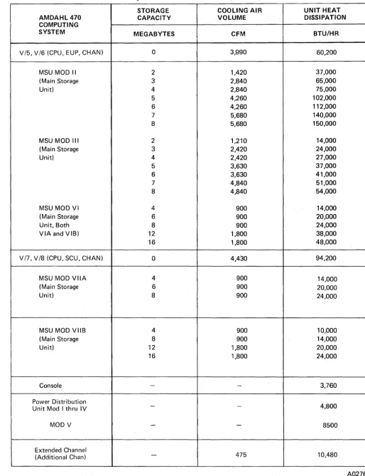
All components of. the Amdahl 470 computing system are air cooled. Cool air is introduced from. beneath the frames, distributed by a push-pull fan arrangement, and exhausted through the top of the frames. The raised floor under the system must distribute cool air at the areas shown as air intakes in the section CCSystem Configurations." All air conditioning equipment should be in place, tested, and ready for operation prior to system installation. Re-fer to table 1 to locate the required cooling air flow (in cubic feet per minute) for the particular system configuration. Also included in table 1 is the heat dissipation value (in BTU per hour) for the selected system configuration. This value represents the amount of heat that the power supplies (and other circuits) generate within that configuration.
The specifications identified as V 15, V/6 and V 17, V 18 provide data for only the three associated basic frames. Also provided is spec-ification data for unique MSU and PDU configurations, Console and the optional Ex-tended Channel frame. For the total require-ments of the system configuration selected, simply add up the applicable specification figures. For example, an Amdahl 470V 18 with sixteen megabyte storage capacity and a MOD V PDU (with no option) will dissipate 130,460 BTU per hour and require 6,230 cubic feet per minute of cooling air flow.
2
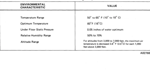
Air at the floor intakes must have a positive pressure .and meet the specifications given'~ in table 2. U nder..;floor air must be maintained at different temperature and humidity ranges than exterior air and must be uniformly distributed through the under-floor sys-tem. Figures 2 and 3 illustrate the system operating range as determined using the tem-perature - relative humidity chart.
Air Filtration
Air supplied to the computer room should be filtered. Special considerations are required when the installation is exposed to corrosive gasses, salt air, or abnormal amounts of dust. A mechanical air filter in a closed air conditioned area should be rated at a minimum of 20 percent efficiency by the Bureau or Standards discoloration test for atmospheric dust; an electrostatic plate air filter for air brought into the air conditioned area should be rated at a minimum of 85 to 90 percent efficiency.
CAUTION
Failure to adhere to Amdahl specifi-cations may lead to degradation of system performance.
SYSTEM FEATURE OPTIONS
The 470V 17 and V 18 option feature Extended Channels is included on tables 1, 6 and 7. The Extended Channel scale layout is illustrated after the system lay~ut diagrams.
The 4 70V 17 and V 18 option feature Hardware Measurement Interface (HMI) is not included in table 1 because the impact on system environmental specifications is negligi-ble. The HMI optional feature frame is de-scribed in the V 17 and V 18 weights and measures tables. The HMI scale layout is illustrated after the system layout diagrams.
Shipping or Storage Temperature Range -'-30° to 60°C Relative Humidity 5% to 100% Max Wet Bulb Temp
*
No Condensationill EXTERIOR ENVIRONMENT (OPERATING) • UNDERFLOOR COOLING AIR
NOTE: MINIMUM UNDERFLOOR STATIC PRESSURE =
1.25 mm OFWATER
o 5 10 15 20 25
Operating
16° to 32°C 30% to 70%
26°C
30 35
DRY BULB TEMPERATURE _oC
40
Figure 2. Environmental Specifications (Metric)
470 Computing System Physical Planning Manual
Nonoperating
10° to 43°C 10% to 80%
.028 .026 .024 .022 .020
a:
.018 « >
a:
.016 Cl (!) ~
.014 ~ w ~
«
.012 :s::
(!) ~
.010 .008 .006 .004 .002
45
A02716
4
Shipping or Storage
Temperature Range _22° to 140° F
Relative Humidity 5% to 100%
Max Wet Bulb Temp
*
No CondensationD
EXTERIOR ENVIRONMENT (OPERATING)• UNDERFLOOR COOLING AIR
NOTE: MAXIMUM UNDERFLOOR
STATIC PRESSURE =
.05 INCHES OF WATER
30 35 40 45 50 55 60 65 70 75
Operating Nonoperating
60° to gO°F 50° to 110°F 30% to 70% 10% to SO% 7SoF
FOR BAROMETRIC PRESSURE OF 29.92 INS. HG.
0.025 0.024 0.023 0.022 0.021 0.020 0.019 0.018 0.017 0.016 0.015 0.014 0.013 0.012 0.011 0.010 0.009 0.008 0.007 0.006 0.005 0.004 0.003 0.002 0.001 0 80 85 90 95 100 105 110
DRY BULB TEMPERATURE - DEG F
Figure 3. Environmental Specifications (American Standard)
cr: ~ >-cr: Cl Cl z :::> 0 0... cr: w 0... cr: w ~ « 5: LL. 0 CIl Cl z :::> 0 0... A02717
Table 1. Cooling Air Volume and Heat Dissipation Specifications
STORAGE COOLING AIR UNIT HEAT AMDAHL 470 CAPACITY VOLUME DISSIPATION COMPUTING
SYSTEM MEGABYTES CFM BTU/HR
V/5, V/6 (CPU, EUP, CHAN)
°
3,990 60,200MSU MOD II 2 1,420 37,000
(Main Storage 3 2,840 65,000
Unit) 4 2,840 75,000
5 4,260 102,000
6 4,260 112,000
7 5,680 140,000
8 5,680 150,000
MSU MOD III 2 1,210 14,000
(Main Storage 3 2,420 24,000
Unit) 4 2,420 27,000
5 3,630 37,000
6 3,630 41,000
7 4,840 51,000
8 4,840 54,000
MSU MOD VI 4 900 14,000
(Main Storage 6 900 20,000
Unit, Both 8 900 24,000
VIA and VIB) 12 ',800 38,000
16 ',800 48,000
V/7, V/8 (CPU, SCU, CHAN)
°
4,430 94,200MSU MOD VilA 4 900 14,000
(Main Storage 6 900 20,000
Unit) 8 900 24,000
MSU MOD VIIB 4 900 10,000
(Main Storage 8 900 14,000
Unit) 12 1,800 20,000
16 1,800 24,000
Console - - 3,760
Power Distribution
4,800
Unit Mod I thru IV -
-MOD V - - 8500
Extended Channel
475 10,480
(Additional Chan)
-A02765
[image:10.617.73.587.53.722.2]Table 2. Under-Floor Cooling Air Specifications
ENVI RONMENTAL CHARACTE RISTIC
Temperature Range
Optimum Temperature
Under Floor Static Pressure
Relative Humidity Range
Altitude Range
SYSTEM POWER
Power must be available to the Amdahl 470 power distribution unit (PDU) at the time of installation. The PDU requires two power sources (208-Vac, 415-Hz, 3-phase and 208-Vac,
50/60-Hz, 3-phase) which are commonly refer-red to as 415-Hz and 50 or 60 Hz power. Both sources must be four wire and three phase.
415 Hertz Power Source
Procurement, installation, and maintenance of the 415 Hz power source is the customer's responsibility. This source can be a motor-generator or a solid-state converter. It must be capable of delivering 415 Hz (+ or -5%) at 208 volts (+ 10%, -5%). The maximum power requirement will be approximately 208 am-peres per phase, 75 kilovoltamam-peres.
50/60 Hertz Power Source
The 60 Hz power source is a typical commercial power line. The maximum power requirement from this source is approximately 60 amperes per phase, 10.8 kilovoltamperes. The 50 Hz is applicable to European installations.
6
VALUE
50° to 65° F (10° to 18° C)
60°F (16°C)
0.05 inches of water optimum
50% to 70%
For altitudes from 3,000 to 7,000 feet, the maximum air temperature is decreased 3.6° F (2.00C) for each 1,000 feet above 3,000 feet.
A02766
The power source voltage in any installations using MODs I through IV A PDUs is:
208 Vac, 60 Hz
The power source voltage in any installations using a MOD IVB PDU can be:
208 Vac, 60 Hz 220 Vac, 50 Hz
The power source voltage in any installations using a MOD V PDU can be:
208/230Vac, 60 Hz
220/230/380/415 Vac, 50 Hz
Power Requirements
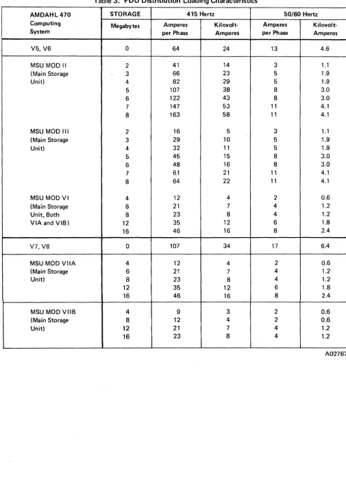
Table 3 gives the power requirements of the Amdahl 470 computing systems and the four MSU types. The items labeled with a system name give the requirements for every frame in that system except the MSU. The items with an MSU name give the requirements for that MSU type. For the total requirements of your system, add the figures for the appropriate type and size of MSU. For example, an Amdahl 470V 16-II computing system with a Mod III, three-megabyte MSU requires 93 amperes per phase from a 415-Hz power source.
[image:11.618.32.536.56.313.2]Table 3. PDU Distribution Loading Characteristics
AMDAHL 470 STORAGE 415 Hertz 50/60 Hertz Computing Megabytes Amperes Kilovolt- Amperes Kilovolt-System per Phase Amperes per Phase Amperes
V5,V6 0 64 24 13 4.6
MSU MOD II 2 41 14 3 1.1
(Main Storage 3 66 23 5 1.9
Unit) 4 82 29 5 1.9
5 107 38 8 3.0
6 122 43 8 3.0
7 147 53 11 4.1
8 163 58 11 4.1
MSU MOD III 2 16 5 3 1.1
(Main Storage 3 29 10 5 1.9
Unit) 4 32 11 5 1.9
5 45 15 8 3.0
6 48 16 8 3.0
7 61 21 11 4.1
8 64 22 11 4.1
MSU MOD VI 4 12 4 2 0.6
(Main Storage 6 21 7 4 1.2
Unit, Both 8 23 8 4 1.2
VIA and VIB) 12 35 12 6 1.8
16 46 16 8 2.4
V7, V8 0 107 34 17 6.4
MSU MOD VilA 4 12 4 2 0.6
(Main Storage 6 21 7 4 1.2
Unit) 8 23 8 4 1.2
12 35 12 6 1.8
16 46 16 8 2.4
MSU MOD VIIB 4 9 3 2 0.6
(Main Storage 8 12 4 2 0.6
Unit) 12 21 7 4 1.2
16 23 8 4 1.2
A02767
[image:12.617.72.577.51.757.2]Motor-Generator Wiring
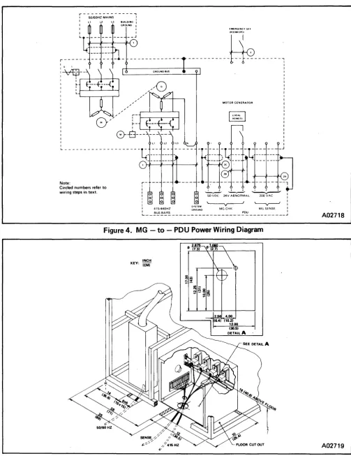
The customer's electrician must provide wiring into the motor-generator (MG) and between the MG and the PDU. Figure 4 illustrates the MG-to-PDU interconnections. The circled numbers correspond to entries in the following wiring descriptions. The American Wire Gauge (A WG) values are for copper wire. The following connections from the MG to the PDU are required:
1. Three-phase power circuit with a ground wire. The size of the lines will be deter-mined by the load and distance of the run. Nonferrous metallic conduit, if al-lowed by local electrical code, is recom-mended for all runs over 60 feet. Plastic conduit is not recommended.
2. Control leads from the MG to the PDU. These leads consist of:
a. Remote sense leads. Use three AWG # 14 (2.0 mm) leads for runs up to 275 feet (84 meters). Use three A WG # 10 (2.5 mm) leads for runs which exceed 275 feet (84 meters).
b. Local/remote indicator leads. Two A WG # 16 (1.5 mm) leads operate the local sensing indicator light. This light indicates whether the voltage is being sensed at the MG or at the PDU. ON indicates local sensing at the MG. OFF indicates remote sens-ing at the PDU. Remote senssens-ing at the PDU is considered normal.
c. Fifty-volt monitoring leads. Use one AWG #16 (1.5 mm) twisted pair in a shielded, jacketed cable. The shield must be grounded at the motor genera-tor only. These leads detect and sig-nal under-voltage from the MG.
The following connection to the MG is optional:
3. Two AWG #14 (2.0 mm) leads from the emergency power off (EPO) switch in the computer room to the MG. These leads remotely cut off the output of the genera-tor. They are for customer use only.
8
At least 12 inches (30 cm) spacing should be maintained between the MG output feeders and the control lines. If this is not possible, the control wiring must be run in its own ferrous conduit.
Solid-State Converter Wiring
A solid-state converter should be wired accord-ing to the manufacturer's specifications. A solid-state converter is an alternative
to
a motor-generator.Power Distribution Unit Wiring
The PDU requires two power sources, 415 Hz and 50/60 Hz. Both are brought in via conduit and hardwired into the PDU. Each conduit terminates in the appropriate PDU safety box. Refer to ((Power Requirements," ((System Grounding," and figures 5 through 7. The customer supplies the wiring between the PDU and the MG or solid-state converter.
System Grounding
An insulated, true earth grounding conductor must be installed as part of the branch circuit that supplies the unit or system. Local code may require that this conductor be identical in both size and insulation to the grounded and ungrounded branch circuit supply conduc-tors. The conductor must be color coded green or green with yellow stripes. This conductor must not be a part of any other system ground and it must be grounded at all service equipment.
Electrical equipment that is to be plugged into the system's 115 Vac, 50/60 Hz, single phase convenience outlet must be of the grounded type. The ground conductor serving the con-venience outlets must be connected to the common ground of the system.
r---, : 50/60HZ MAINS BUILDING!
I GROUND I
r
-I I
__ .I
---~---"
MOTOR GENERATOR
---[ ---r----
L -- -
t ---
_.I· :::::-:::--
: -::- i: : :::
1:
=~-- =~~=~
'.
Note: r - - - -;-- - - ,
Circled numbers refer t o : I 1 3 4 I 1 3
wiring steps In text. : 0 ~ 24V~AL ~
I 0
I 0
I
:
!~~~~~~ GROUND MG CHK PDU MG SENSE I~ _ _ _ _ _ _ _ _ _ _ _ _ _ _ _ _ _ _ _ _ _ _ _ _ _ _ _ _ _ _ _ _ _ _ _ _ _ J
Figure 4. MG - to - PDU Power Wiring Diagram
INCH KEY: (CM)
Figure 5. PDU Mod I, Interconnection Wiring Block
470 Computing System Physical Planning Manual
A02718
A02719
[image:14.615.63.567.56.710.2]10
* Distances above floor are approximate, exact distance dpends upon caster adjustment
SENSE WIRES
~ 1.063 IN. (2.700 eM)
SENSE WIRES
~ 1.063 IN. (2.700 eM)
I
DETAIL AI
I
PLATE DIMENSIONSl
15.4 IN x 5.5 IN. ((39CM x 14CM) J
GROUND LUGS 211N. (53 eM) ABOVE FLOOR
SENSE WIRE TERMINAL BOARDS 17 IN. (43 CM) ABOVE FLOOR
Figure 6. PDU MODs II, III and IV, Interconnection Wiring Block
A02720
415/440 Hz
50/60 Hz POWER
8r GROUND LUGS
25 em (10 in.) ABOVE FLOOR·
SENSE WIRES DIAMETER: 2.700 em
(1.063 in.) ---"'oo,~:=----2~;;;:--_~~~
__ ""","",,
50/60 Hz POWER DIAMETER: 3.492 em
(1.375 in.)
415/440 Hz POWER DIAMETER: 7.302 em
(2.875 in.)
• DISTANCES ABOVE FLOOR ARE APPROXIMATE; EXACT DISTANCES DEPEND UPON CASTER ADJUSTMENT
Figure 7. PDU MOD V, Interconnection Wiring Block
470 Computing System Physical Planni'ng Manual
415/440 Hz REMOTE SENSE TERMINALS 46 em (18 in.) ABOVE FLOOR·
I
SENSE WIRE TERMINAL BOARDS 43 em (17 in.) ABOVE FLOOR·
III
IPB'()33
A02721
V/5
AND
V/6
UNITS, FRAME
DIMENSIONS AND WEIGHTS
Table 4 lists the frame dimensions without covers. Table 5 lists the frame dimensions with covers and the installed weights. Refer to figures 8 through 27 to identify which frame will be on your system.
Table 4. VIS and V/6 Frame Dimensions (Without Covers)
DEPTH HEIGHT
FRAME
In. em. In. em.
Central Processing Unit 70 178 64 163
External Unit Processor 24 61 64 163
Cable Duct 30 76 * *
(2 or 3 MSU Frames)
Cable Duct 90 229 * *
(4 MSU Frames)
Main Storage Unit 72 183 64 163
(Mod II or Mod III)
Main Storage Unit 48 122 64 163
(Mod VI)
Console Equipment Frame 63 160 29 74
Console Pedestal 64 163 29 74
Console CRT 26 66 24 61
Power Distribution Unit 48 122 64 163
(MOD II, '", IV)
(PDU MOD I Only) 88 224 64 163
Channel Unit 26 66 64 163
Channel and Cable Entry 48 122 64 163
* A cable duct is shipped as a disassembled unit. Height does not apply until unit is installed.
WIDTH
In. em.
26 66
26 66
30 76
30 76
26 66
26 66
34 86
24 61
26 66
26 66
26 66
26 66
26 66
A02768
Table 5. V /5 and V /6 Frame Dimensions and Weights (With Covers)
DEPTH HEIGHT WIDTH WEIGHT FRAME
In. em. In. em. In. em. lbs. Kg.
Central Processing Unit 70 178 64.5 164 30 76 1,607 729
External Unit Processor 24 61 64.5 164 30 76 436 198
Cable Duct 30 76 64.5 164 30 76 100 45
(2 or 3 MSU Frames)
Cable Duct 90 229 64.5 164 30 76 100 45
(4 MSU Frames)
Main Storage Unit 74 188 64.5 164 30 76 848 385
(Mod II or Mod III)
Main Storage Unit 50 127 64.5 164 30 76 1,000 454
(Mod VI)
Console Equipment Frame 63 160 29 74 34 86 785 356
Console Pedestal 64 163 29 74 24 61 40 18
Console CRT 26 66 24 61 26 66 70 32
Power Distribution Unit 52 132 64.5 164 30 76 900 409
(MOD II, III, IV)
(PDU MOD I Only) 92 234 64.5 164 30 76 1125 510
Channel Unit 26 66 64.5 164 30 76 613 278
Channel and Cable Entry 50 127 64.5 164 30 76 965 438
A02769
V/7
AND
V/8
UNITS, FRAME
DIMENSIONS AND WEIGHTS
Table 6 lists the frame dimensions without covers. Table 7 lists the frame dimensions with covers and the installed weights. Refer to figures 28 through 43 to identify which frames will be on your system.
Table 6. V /7 and V /8 Frame Dimensions (Without Covers)
DEPTH HEIGHT FRAME
In. em. In. Cm.
Central Processing Unit 72 183 64 163
Storage Control Unit 24 61 64 163
Cable Duct 30 76 * *
(2 MSU Frames)
Main Storage Unit 48 122 64 163 (Mod VII)
Console Equipment Frame 63 160 29 74
Console Pedestal 64 163 29 74
Console CRT 26 66 24 61
Power Distribution Unit 48 122 64 163 (PDU Mod V only) 51 130 64 163
Channel Unit 24 61 64 163
Channel and Cable Entry 48 122 64 163
Hardware Measurement 26 66 64 163 Interface (Optional)
* A cable duct is shipped as a disassembled unit. Height does not apply until unit is installed.
WIDTH
In. Cm.
26 66
26 66
30 76
26 66·
34 86
24 61
26 66
26 66 36 92
26 66
26 66
24 61
A02770
Table 7. V /7 and V /8 Frame Dimensions and Weight (With Covers)
DEPTH HEIGHT WIDTH WEIGHT FRAME
In. em. In. em. In. em. Lbs. Kg.
Central Processing Unit 72 183 64.5 164 30 76 1,700 771
Storage Control Unit 24 61 64.5 164 30 76 650 295
Cable Duct 30 76 64.5 164 30 76 100 45
Main Storage Unit 50 127 64.5 164 30 76 1,000 454 (Mod VII)
Console Equipment Frame 63 160 29 74 34 86 785 356
Console Pedestal 64 163 29 74 24 61 40 18
Console CRT 26 66 24 61 26 66 70 32
Power Distribution Unit 52 132 64.5 164 30 76 900 409 (MOD II, III, IV)
(PDU V ONLY) 51.5 132 64.5 164 36.5 93 1400 636 Channel Unit 24 61 64.5 164 30 76 650 295
Channel and Cable Entry 50 127 64.5 164 30 76 965 438
Hardware Measurement 30 76 64.5 164 28 71 255 100 Interface (Optional)
A02771
SYSTEM CABLE REQUIREMENTS
The interframe power and power-control cables required to connect the PDU to the CPU, MSU, and console are supplied with the system. A standard power cable length of 50 feet deter-mines the distance the PDU can be removed from the system. The console must be placed within 100 feet of the CPU and PDU. To facilitate maintenance, the console should also be within 35 feet of the system and in the same room as the system.
If a channel-to-channel adapter is ordered, Amdahl will supply cables from the adapter to the other channel.
The customer supplies input/output cables and EPa cables between control units and from the channel/cable entry frame to the first control unit.
SYSTEM CONFIGURATIONS
Figures 8 through 48 show scale drawings of the various Amdahl 470 computing system configurations, indicating service clearances, the position of cable entries, and the location of air intakes. Each scale layout figure has a corresponding raised-floor tile installation pat-tern diagram on the following page of the figure. Cutout diagrams showing dimensions are located at the end of this manual.
The illustrations can be cut out to serve as templates for use when laying out computer room plans.
RAISED-FLOOR TILE CUTOUTS
The illustrations following each system configu-ration show the proper placement of the raised floor tile installation pattern for the various Amdahl 470 computing system configura-tions. Tile cutouts for the console are not included because their location depends upon the position of the console. The cutouts for the console should be minimized to reduce air loss.
16
All measurements for cutouts apply to 24-inch-by-24-inch floor tiles. Customers with floor tiles of a different dimension should contact their Amdahl installation planning representa-tive for instructions.
The raised floor of the computer room must be capable of supporting 65 pounds per square foot. If a PDU MOD V unit is being installed the floor must be capable of supporting 100 pounds per square foot. Amdahl recommends that the floor of a new room be built to support 100 pounds per square foot (220 kg per square meter).
It is recommended that the floor has channel-iron stringers to ensure that the floor has additional support after the floor tile has been cut. Other types of flooring may require additional support. Additional floor support may be required for the CPU and PDU MOD V. Contact your Amdahl installation plan-ning representative for further details.
FIELD ENGINEER ROOM
REQUIREMENTS
To support the Amdahl maintenance effort, the customer must provide for the field engineer an onsite work area of approximately 200 square feet. Amdahl will provide the neces-sary furniture. The systems engineer will also need a work area. This is normally a desk in the customer's programming area.
A telephone line terminated at the console with a standard modular jack is required. This telephone line will be used for the remote diagnostic facility, Amdahl Diagnostic Assist-ance Center (AMDAC).
SYSTEM INPUT/OUTPUT
EQUIPMENT
Refer to the Amdahl 4705 Communications Processor Physical Planning Manual (Publica-tion G 1022.0). This publication provides the necessary specification information for the Amdahl 4705 Communication Processor.
154 IN.
(391 CM)
~I
r--- ---,
: MODVI :
: MOD II OR MOD III MAIN STORAGE
I
: MAIN STORAGE UNIT UNIT I
- : - - - ~e eEJ:lj(£l_.,~ CA~BLE ~! lea;
---l--.-I
rvI : 30 IN.I ~ ~ I (76CM)
L____
m effi!ffi' eDUCT' leRl _ _ _ _ _ _J---.i
200 IN. (508 CM) I I I I I I I
L ________ ,
30 IN. (76 CM)
FJI["
RI' Fg
!=B. ~E!
I
I
I
I I
I I L _____ ...J
I.
~I
EXTERNAL I
UNIT :
PROCESSOR J
" r--..J I
I
I
I
CENTRAL PROCESSING
~
UNIT:I I
I
I I
I CHANNEL
UNIT I
I I I CHANNEL I I I
CABLE t
ENTRY:
______ .J LEGEND
~
Air Intake•
Castere
Leveling Pad[g)
Cable Entry Service Clearance (All Are 30 Inches)Scale 1/4 in. = 12 In.
Note: Two megabytes Mod II or Mod III MSU and two, four, or six megabytes Mod VI MSU configuration 1. Raised-floor tile cutouts for this configuration are shown in Figure 9. Scale layouts for the console and power distribution unit appear in Figures 38 and 39.
Figure 8. V/5 and V/6 Scale Layout Showing "Long-Left-T," Configuration 1
470 Computing System Physical Planning Manual
A02722
18
REMOVE TILE
REFER TO RAISED-FLOOR TILE CUTOUTS AT END OF BOOK FOR DIMENSIONS
3 9
11
THE CONSOLE REQUIRES A SPECIAL CABLE ENTRY TILE CUTOUT, THE LOCATION OF WHICH DEPENDS ON CONSOLE POSITIONING. THE CUT-OUT DIMENSIONS MUST BE MINI-MIZED TO REDUCE AIR LOSS.
REFER TO FIGURE 8
POWER DISTRIBUTION UNIT
A02723
Figure 9. V /5 and V /6 Alternate Configuration 1. Raised-Floor Tile Installation Pattern.
200 IN. (508 CM)
154 IN. (391 CM)
r--- - - - ----1
I I
I
I~ MOD VI MOD II OR MOD III
I
M~IN STORAGE UNIT MAIN STORAGE UNIT:
i---
---[~!.Ib~~~~~-~-!-!I~i-C-A-~-L-E"'~II·-I-I-I~I-IlilrlUli:i1!111.--~IIIIIII!.
E:fju -'--'--1
~~I
I .1
itt
DUCT :Ii fjrIJ..~ I ..L __ m' _-"_J---1..
I
~JI["~ EXTERNAL :I UNIT I
I I
I Ea ~6 PROCESSOR I
I , I
I 19. ~rJ
~--, r---~
, I
I I
I I
, CENTRAL
: PROCESSING
: UNIT I
I I
, I
I I
I et- "jJJ I
1
~. ~.fE
CHANNEL I • • UNIT I,m "Eli
:
I~I··f!l
CHANNEL:
I • I
I Ea Eli I
I
~Ia.'
.,g
II CABLE I
: ENTRY:
L ______ ... _ ... ______ ..J
30 IN. (76 CM)
I
,
I I
I I
L _ _ _ _ .J
---LEGEND
Air Intake Caster Leveling Pad Cable Entry Service Clearance (All Are 30 Inches)
Scale 1/4 In. = 12 In.
Note: Two megabytes Mod II or Mod III MSU and two, four, or six megabytes Mod VI MSU configuration 2. Raised-floor tile cutouts for this configuration are shown in Figure 11. Scale layouts for the console and power distribution unit appear in Figures 38 and 39.
Figure 10. V /5 and V /6 Scale Layout Showing IILong-Right-T", Configuration 2
470 Computing System Physical Planning Manual
A02724
[image:24.618.64.561.77.671.2]20
9 10 "
-REMOVE TILE
REFER TO RAISED-FLOOR TILE CUTOUTS AT END OF BOOK FOR DIMENSIONS
8
POWER DISTRIBUTION UNIT
THE CONSOLE REQUIRES A SPECIAL CABLE ENTRY TILE CUTOUT, THE LOCATION OF WHICH DEPENDS ON CONSOLE POSITIONING. THE CUT-OUT DIMENSIONS MUST BE MINI-MIZED TO REDUCE AIR LOSS.
REFER TO FIGURE 10
A02725
Figure 11. V /5 and V /6 Alternate Configuration 2, Raised-Floor Tile Installation Pattern.
250 IN. (635 CM)
r---l
I I
I I
104 IN. (264 CM)
!
MOD VIl
MAIN STORAGE UNITr - - - . . ~!!!!1111 . . - - ' - - - - _ ,
I ~. ~
.'dJ
I~I
I MOD II OR MOD III :
i
~ ~
L---
1
: m
~(±
MAIN STORAGE UNIT:F~--=~"'----I11111111!111~-"""\11-'-
---•
CA~E ~1.·llIllr· ~
i
'---DUCT ~ GJ~.·a; I
~~~~----I----~~--~---~
I
I I
,
~~~ EXTERNAL II _ UNIT
~' 'f) PROCESSOR
I
~ ~
r---~
I I I I CENTRAL PROCESSING UNIT I
I
I I
I I
I
CHANNEL UNIT I
I I I CHANNEL I I
CABLE I
ENTRY
l
______ .JI ,
L _____ .J
•
---30 IN.
1..
./
(76 CM)Scale
.-
30 IN. (76 CM)~
LEGEND
Air Intake Caster Leveling Pad Cable Entry Service Clearance (All Are 30 Inches)
1/4 In. = 12 In.
Note: Two megabytes Mod II or Mod III MSU and two, four, orsix megabytes Mod VI MSU configuration 3. Raised-floor tile cutouts for this configuration are shown in Figure 13. Scale layouts for the console and power distribution unit appear in Figures 38 and 39.
Figure 12. V /5 and V /6 Scale Layout Showing IILong-Right-L", Configuration 3
470 Computing System Physical Planning Manual
A02726
22
REMOVE TILE
3
1
5
6
7
REFER TO RAISED-FLOOR TI LE CUTOUTSATENDOFBOOK FOR DIMENSIONS
8
POWER DISTRIBUTION UNIT
THE CONSOLE REQUIRES A SPECIAL CABLE ENTRY TI LE CUTOUT. THE LOCATION OF WHICH DEPENDS ON CONSOLE POSITIONING. THE CUT-OUT DIMENSIONS MUST BE MINI-MIZED TO REDUCE AIR LOSS.
REFER TO FIGURE 12
A02727
Figure 13. V /5 and V /6 Alternate Configuration 3 Raised-Floor Tile Installation Pattern.
•
r---30 IN. I
1
(76 CM) 1
104 IN.
(264 CM) ,---, ~I
I I
: I
: MODVI : MAIN STORAGE UNIT
r - - - . . ~~ . . ---...,
I I I
,---1
I II
MOD II OR MOD III: MAIN STORAGE UNIT
~,--- L---~--~
I
..
---~~~~d
EXTERNALI
UNIT :I
PROCESSORI I
L ________ , I
I I
I I
I I
I CENTRAL
I
PROCESSINGI UNIT I
I I
I I
I I
I I
I I
I
I
CHANNEL: UNIT
I
1 I
I I
I CHANNEL
I I
I I
I I
I I
I I
I I
L _____ ~ ___ . . ______ --'
30 IN. (76 CM). I I I I
I L _____ J I
I.
~I
Scale 1/4In.=12In.
250 IN. (635 CM)
•
LEGEND
Air Intake Caster Leveling Pad Cable Entry Service Clearance (All Are 30 Inches)
Note: Two megabytes Mod II or Mod III MSU and two, four, or six megabytes Mod VI MSU configuration 4. Raised-floor tile cutouts for this configuration are shown in Figure 15. Scale layouts for the console and power distribution unit appear in Figures 38 and 39.
Figure 14. V /5 and V /6 Scale Layout Showing IlLong-Left-L", Configuration 4
470 Computing System Physical Planning Manual
A02728
24
8
REMOVE TILE
REFER TO RAISED-FLOOR TI LE CUTOUTS AT ENDOF BOOK FOR DIMENSIONS
5
6
POWER DISTRIBUTION UNIT
THE CONSOLE REQUIRES A SPECIAL CABLE ENTRY TILE CUTOUT, THE
LOCATION OF WHICH DEPENDS ON CONSOLE POSITIONING. THE CUT-OUT DIMENSIONS MUST BE MINI-MIZED TO REDUCE AIR LOSS.
REFER TO FIGURE 14
A02729
Figure 15. V /5 and V /6 Alternate Configuration 4 Raised-Floor Tile Installation Pattern.
274 IN. (696 CM)
I~
80 IN.(203 CM)
r---,
I I
I
I
I I
I I
I I
I I
r - - - . , - - -
-II'~ . - :
,
. . . I :::IilI~r-e---';.~~
I
I
>
MOD II OR MOD III MAIN STORAGE UNIT----,
I
I
MOD VI
be
.9
I) MAIN STORAGE UNIT---,
CABLE
iRe
I_ Vi I~
1 8 J :
lr~D~U~C~T~~i~~~~!I_~.QJ
IpDJI[-~ EXTERNAL , ______ J
UNIT :
~. "II PROCESSOR
I
~.
.fJ \
1---1 I II
CENT~AL
PROCESSING
UNIT I
I I
~.
ltd!I
! B Q l ) I• mm -
CHANNE L.~. UNIT : .
!B • d! ,
!BI
.Ql II CHANNEL
:
~. .~:
I
~_
,g
I:' CABLE
I ENTRY
1 m . L______ _ _____ ...1 I
30 IN. (76 CM)
I
I I
I I
I
IL _____ J
I·
~I
.-30 IN. (76 CM)
i
LEGEND
~
Air Intake•
Caster•
Leveling Padrg)
Cable Entry Service Clearance (All Are 30 Inches)Scale 1/4 In. = 12 In.
Note: Two megabytes Mod II or Mod III MSU and two, four, or six megabytes Mod VI MSU configuration 5. Raised-floor tile cutouts for this configuration are shown in Figure 17. Scale layouts for the console and power distribution unit appear in Figures 38 and 39.
Figure 16. V /5 and V /6 Scale Layout Showing IIShort-Right-L", Configuration 5
470 Computing System Physical Planning Manual
A02730
26
REMOVE TILE
REFER TO RAISED-FLOOR TI LE CUTOUTSATENDOFBOOK FOR DIMENSIONS
5
THE CONSOLE REQUIRES A SPECIAL CABLE ENTRY TILE CUTOUT, THE LOCATION OF WHICH DEPENDS ON CONSOLE POSITION ING. THE CUT-OUT DIMENSIONS MUST BE MINi-MIZED TO REDUCE AIR LOSS.
REFER TO FIGURE 16
9 ~-2--"11
POWER DISTRIBUTION UNIT
A02731
Figure 17. V /5 and V /6 Alternate Configuration 5 Raised-Floor Tile Installation Pattern.
.-30 IN. (76 CM)
L
I ....
80 IN.(203 CM) ~I
,----
-,, I
I
:
I I
, I
, I
I I
r---
----,
I ltiecg;J elll
I
I I
I ~ e61 I
, ~ ~ I
,_-1
: I
MAIN STORAGE UNIT MOD II OR MOD III:
II
:
MOD VI I
MAIN STORAGE UNIT I
I
m
ffi II
r
, - - - -
~ii~ii9rc~~~
reFII!
CABLE II,~
C8J .
I I_Lm~e!b~~~~i~~D~U~C~T~
IL ___ -- :
FI'-mfiTrtB
EXTERNlL: _ UNIT
: m · Ell PROCESSOR
I ~t ~ei :
L __ , I
I I
I '
I CENTRAL
I PROCESSING
,
UNIT
I ,
I ,
I ,
,
,
I m : e I
i
e.~eEll CHANNE~
I UNIT I
I me eg: I
:,
~I· .~
CHANNEL:
: m eEll
I
I:
~m·
e , g CABLE :ENTRY
l
L ________ - -________ J
I
I
I I
I
, I
L _____ J
274 IN. (696 CM)
•
LEGEND
Air Intake Caster leveling Pad Cable Entry
30 IN.
(76CM) ~I Scale 1/4In.=12In.
Service Clearance (All Are 30 Inches)
Note: Two megabytes Mod II or Mod III MSU and two, four, or six megabytes Mod VI MSU configuration 6. Raised-floor tile cutouts for this configuration are shown in Figure 19. Scale layouts for the console and
power distribution unit appear in Figures 38 and 39. A02732
Figure 18. V /5 and V /6 Scale Layout Showing IIShort-Left-L", Configuration 6
28
9
REMOVE TILE
REFER TO RAISED-FLOOR TILE CUTOUTSATENDOFBOOK FOR DIMENSIONS
8
THE CONSOLE REQUIRES A SPECIAL CABLE ENTRY TILE CUTOUT, THE LOCATION OF WHICH DEPENDS ON CONSOLE POSITIONING. THE CUT-OUT DIMENSIONS MUST BE MINI-MIZED TO REDUCE AIR LOSS.
REFER TO FIGURE 18
POWER DISTR IBUTION UNIT
A02733
Figure 19. V /5 and V /6 Alternate Configuration 6 Raised-Floor Tile Installation Pattern .
.
I.
178 IN.~I
(452 CM)
,---1
I I
I I
I I
I I
I I I I
r--
- - lI
~.
181
.aJ
l
I~ MOD II OR MOD III MOD II OR MOD III
I
r---
J
~ ~ MAINS~g~:~EUNIT
: MAIN STORAGE UNIT m' r~ MAIN STORAGE UNIT
I
!--·--·--~~~·---~~~·[----~---r~C-A-~-B-LE~~PIt£---J~:~M~~
•.---~R--~--l(;~~l
L
______
w~~_~~~
__
~
__
~"~~-D=U=C~T~~~--.---~G~~-~~---J ~
250 IN.
(635 CM)
~ P'lJI['~ EXTERNAL
l
: U N I T :
I AI "ll PROCESSOR I
: JB. . Ql , I
L _ _ _ _ _ - - , • It r--- J
I I
I I
I I
I CENTRAL
: PROCESSING
I
UNITI I
I
I
'el. Iffi I I
~.
mm·
ijJCHANNE~
II
UNIT I=1-'
:~
CHANNElm
.JIlI
m
~··
.,g
CABLEI
ENTRY I
I _______ ... _ . . ______ .J
I
I
I
I
I
I I
L _ _ _ _ -.1
30 IN. ~1."----i.~1
(76 CM)
~
•
•
rg)
Scale LEGENDAir Intake Caster Leveling Pad Cable Entry Service Clearance (All Are 30 Inches)
1/4 In. = 12 In.
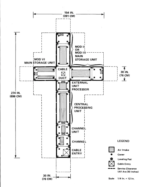
Note: Four megabytes Mod II or Mod III MSU and two, four, six or eight megabytes Mod VI MSU alternate configuration 1. Raised-floor tile cutouts for this configurations are shown in Figure 21. Scale layouts for the console and the power distribution unit appear in Figures 38 and 39.
Figure 20. V /5 and V /6 Scale Layout Showing IIBalanced-L", Alternate Configuration 1
470 Computing System Physical Planning Manual
A02734
30
8
REMOVE TILE
REFER TO RAISED-FLOOR TILE CUTOUTS AT END OF BOOK FOR DIMENSIONS
5
6
7
8
POWER DISTRIBUTION UNIT
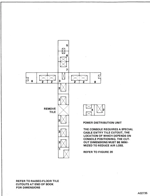
THE CONSOLE REQUIRES A SPECIAL CABLE ENTRY TILE CUTOUT, THE LOCATION OF WHICH DEPENDS ON CONSOLE POSITIONING. THE CUT-OUT DIMENSIONS MUST BE MINI-MIZED TO REDUCE AIR LOSS.
REFER TO FIGURE 20
[image:35.617.37.540.56.714.2]A02735
Figure 21. V /5 and V /6 Alternate Configuration 1, Raised-Floor Tile Installation Pattern.
r - - J
I
I
lMODVI
154 IN. (391 CM) r - - - ,
, I
I ,
I I I I
I I
, I
- - - - I
I
,
,
,
I MODII OR :MOD 111---, I
MAIN
I
MAIN STORAGE UNIT •
STORAGE UNIT :
I
I
I
r - - - --III' ....
--.J--....
,...---4 . . ---....,~--g---,
:
• b¥;;;;;gtIl
l
I I
L _____
I;:~~~~~i~~~~~~::::~L.-:J---
I ,__
J
274 IN. (696 CM)
I ,
I I
I I
I I
I I
L __ ., r - - - . I
I I I CENTRAL PROCESSING UNIT: I I I I I CHANNEL UNIT I
I
I
I I
I CHANNEL
I I
I I
I CABLE I
: ENTRY:
L ______ ~, ___ ~ ______ -.1 I
I
I
I
, I
L _____ ...l
•
---
,-30 IN. (76CM)
-'-LEGEND
Air Intake Caster
Leveling Pad Cable Entry Service Clearance (All Are 30 Inches) 30 IN. -+4+-4,--~J
(76 CM) ~ Scale 1/4 In. = 12 In.
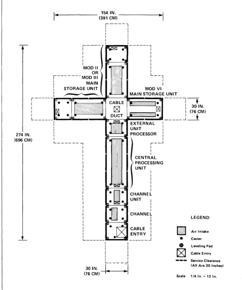
Note: Four megabytes Mod II or Mod III MSU and two, four, six or eight megabytes Mod VI MSU alternate configuration 2. Raised-floor tile cutouts for this configurations are shown in Figure 23. Scale layouts
[image:36.615.61.560.68.670.2]for the console and the power distribution unit appear in Figures 38 and 39. A02736
Figure 22. V /5 and V /6 Scale Layout Showing IILong-Right-L", Alternate Configuration 2
32
1 0 "--'t'--~ 9
REMOVE TILE
REFER TO RAISED-FLOOR TILE CUTOUTS AT END OF BOOK FOR DIMENSIONS
8
8
POWER DISTRIBUTION UNIT
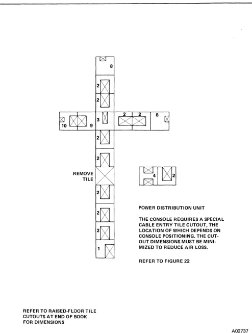
THE CONSOLE REQUIRES A SPECIAL CABLE ENTRY TI LE CUTOUT, THE LOCATION OF WHICH DEPENDS ON CONSOLE POSITIONING. THE CUT-OUT DIMENSIONS MUST BE MINI-MIZED TO REDUCE AIR LOSS.
REFER TO FIGURE 22
[image:37.618.48.543.58.711.2]A02737
Figure 23. V /5 and V /6 Alternate Configuration 2. Raised-Floor Tile Installation Pattern.
154 IN.
(391 CM)
, - - - - l
I I I I I I I I
I I
I I
' - - - - 7
I 1&Jet8J .61
---, I I I I I I I MODII OR
r--- -- --
MOD III I: MAIN
" . , I
. ~ e; I
"111111!lil
~
:11111i!
L--1
l
STORAGE UN ITI~ \ ffi
•I!II!II "
IIIIIII -
fI MAIN STORAGE UNIT MOD VI:---
"'.
·.:~~M-;---.
cg~ CD~UBCLTE IEB!:~~~~I;:
---l--:+;No
L _____
J~~!...!ttJItttE:=:=I:I~~IL:::J§J~!!~~~~'~~J
_____
J
~M)
274 IN. (696 CM)
I I I I I I I
L _ _ _ _ _ _ -,
ft'O'~ EXTERNAL UNIT
m -EI PROCESSOR
I I I I I I
~. ~e: \
r
r - - J I II
CENTR~L
PROCESSING
I
UNITI
I I
ffi41 11113 I
I
I I e.
~.W
UNIT I
m·
·EIl ICHANNEL
~1.fjJ
I
CHANNEL
~ .J13
I
ENTRY
I
m
~
•••g
CABLE I IL __ . __ . __ .iIIiI ... _1IIlIlIiIi ______ -1
30 IN. (76 CM)
I
I I
I
: I
L _ _ _ _ -1
I.
~I
LEGEND
~
Air Intake•
Caster•
Leveling PadrxJ
Cable EntryService Clearance (All Are 30 Inches)
Scale 1/4 In. = 12 In.
[image:38.615.66.565.72.670.2]Note: Four megabytes Mod II or Mod III MSU and two, four, six or eight megabytes Mod VI MSU alternate configuration 3. Raised-floor tile cutouts for this configurations are shown in Figure 25.Scale layouts for the console and the power distribution unit appear in Figures 38 and 39.
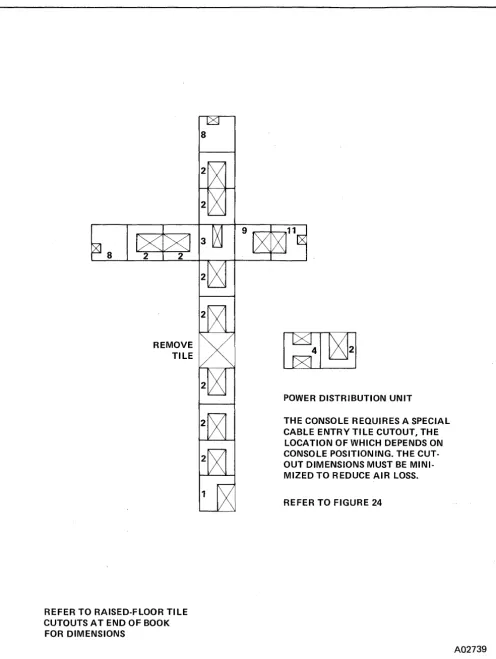
Figure 24. V /5 and V /6 Scale Layout Showing IILong-Left-L", Alternate Configuration 3
470 Computing System Physical Planning Manual
A02738
34
8
REMOVE TILE
REFER TO RAISED-FLOOR TILE CUTOUTSATENDOFBOOK FOR DIMENSIONS
8
9 ~+-....,,11
POWER DISTRIBUTION UNIT
THE CONSOLE REQUIRES A SPECIAL CABLE ENTRY TI LE CUTOUT, THE LOCATION OF WHICH DEPENDS ON CONSOLE POSITIONING. THE CUT-OUT DIMENSIONS MUST BE MINI-MIZED TO REDUCE AIR LOSS.
REFER TO FIGURE 24
[image:39.617.47.543.56.715.2]A02739
Figure 25. V /5 and V
/6.
Alternate Configuration 3, Raised-Floor Tile Installation Pattern.220 IN. (559 CM)
I----l
I II I
I I
I I I I I I
r - - ---- ---,
I I I
MOD VI MAIN STORAGE UNIT
I
I
I I
EXTERNAL UNIT : PROCESSOR : 3 I f - - - - t E I
I I I I I CENTRAL PROCESSING UNIT I
I I I I I I CHANNEL UNIT I
I I I CHANNEL I I I I
: ENTRY :
L_____ _ _____ J
I I
I I
I I
I I
I I
I I
L _____ .J
30 IN.
I
I(76 CM)"
-"t
~
•
•
~
---Scale LEGEND
Air Intake Caster Leveling Pad Cable Entry Service Clearance (All Are 30 I nches~
1/4 In. = 12 In.
[image:40.615.62.572.65.694.2]Note: Two, four, six, or eight megabytes Mod VI MSU only. Raised-floor tile cutouts for this configuration are shown in Figure 27. Scale layouts for the console and power distribution unit appear in Figures 38 and 39.
Figure 26. V /5 and V /6 Scale Layout Showing 6IBasic-I", Configuration 8
4 70 Computing System Physical Planning Manual
A02740
36
REMOVE TILE
6
7
REFER TO RAISED-FLOOR TILE CUTOUTSATENDOFBOOK FOR DIMENSIONS
POWER DISTRIBUTION UNIT
THE CONSOLE REQUIRES A SPECIAL CABLE ENTRY TILE CUTOUT, THE LOCATION OF WHICH DEPENDS ON CONSOLE POSITIONING. THE CUT-OUT DIMENSIONS MUST BE MINI-MIZED TO REDUCE AIR LOSS.
REFER TO FIGURE 26
[image:41.612.43.540.57.708.2]A02741
Figure 27. V /5 and V /6 Alternate Configuration 8. Raised-Floor Tile Installation Pattern.
220 IN.
(559 CM)
,----,
I ,
I , I I
I I
I I
I I I I
,---
---,
I
I
MOD VII MAIN STORAGE UNIT
I I I I STORAGE CONTROL
UNIT I
:5---=: I
I I I I I CENTRAL PROCESSING
UNIT I
I I I I I I CHANNEL
UNIT :
=---= I
I
CHANNEL
I
I
CABLE :
ENTRY I
I
L __ ____ _ _____ J
I I
I I
I I
I I
I I
I
I L _ _ _ _ -l30 IN.
I
I
(76 CM)'" ~
~
•
•
rg)
---Scale LEGENDAir Intake Caster Leveling Pad Cable Entry Service Clearance (All Are 30 Inches)
1/4 In. = 12 In.
Note: Mod V IIA or VIIB MSU. Raised-floor tile cutouts for this configuration are shown in
Figure 29. Scale layouts for the console and power distribution unit appear in Figures 38 and 39.
[image:42.615.66.574.67.696.2]A02742
Figure 28. V!7 and V!8 Scale Layout Showing IIBasic-I", Configuration 1 (Without Cable Duct)
10
9
PDU (MOD II - IV)
THE CONSOLE REQUIRES A SPECIAL CABLE ENTRY TI LE CUTOUT, THE LOCATION OF WHICH DEPENDS ON CONSOLE POSITIONING. THE CUT-OUT DIMENSIONS MUST BE MINI-MIZED TO REDUCE AIR LOSS.
REFER TO FIGURE 28
PDU (MOD V)
~
112
~131
POWER DISTRIBUTION UNIT
REFER TO RAISED-FLOOR TILE CUTOUTSATENDOFBOOK FOR DIMENSIONS
" - - REMOVE TILE AFTER INSTALLING AND SECURING PDU.
[image:43.613.51.532.66.720.2]A02743
Figure 29. V /7 and V /8 Configuration 1, (Without Cable Ducts). Raised-Floor Tile Installation Pattern.
r - - - ,
I I
I I
I I
I I
I I
I I
I I
r - - - ,
I
I MOD VII MAIN STORAGE UNIT
I
,
,
I I,
250 IN. I
(635 CM):
I I I
,
t I I I,
,
I I I I I I I I I I I I I STORAGE CONTROL UNIT I I I CENTRAL PROCESSING UNIT' I,
I I I I CHANNELUNIT I
I I
I
CHANNEL
I ,
I I
: CABLE :
: ENTRY :
L __________________ .J
30 IN. (76 CM)
I I
I I
I I
I I
I I
~ I
L _ _ _ _ - '
I..
~I
~
•
•
[g1
Scale
LEGEND
Air Intake Caster leveling Pad Cable Entry Service Clearance (All Are 30 Inches)
1/4 In. = 12 In.
Note: Mod VilA or VIIB MSU. Raised-floor tile cutouts for this configuration are shown in
[image:44.612.60.566.67.723.2]Figure 31. Scale layouts for the console and power distribution unit appear in Figures 38 and 39.
Figure 30. V /7 and V /8 Scale Layout Showing IIBasic-I", Configuration 1 (With Cable Duct)
4 70 Computing System Physical Planning Manual
A02744
40
REMOVE TILE
PDU (MOD II - IV)
~
5
6
7
8
THE CONSOLE REQUIRES A SPECIAL CABLE ENTRY TILE CUTOUT, THE LOCATION OF WHICH DEPENDS ON CONSOLE POSITIONING. THE CUT-OUT DIMENSIONS MUST BE MINI-MIZED TO REDUCE AIR LOSS.
REFER TO FIGURE 30
PDU (MOD V)
/12
iJX@f!
" - REMOVE TILE AFTER
POWER DISTRIBUTION UNIT INSTALLING AND SECURING PDU
REFER TO RAISED-FLOOR TILE CUTOUTSATENDOFBOOK FOR DIMENSIONS
[image:45.613.47.541.48.714.2]A02745
Figure 31. V /7 and V /8 Configuration 1, (With Cable Ducts). Raised-Floor Tile Installation Pattern.
130 IN.
(330 CM) ---1·~1
r - - -
--1
I I
I
II MOD VII MOD VII I MAIN STORAGE UNIT MAIN STORAGE UNIT
r---
IfJ Itt1 lelil'---lt
I are! !j CABLE
!
:
I 30 IN.l~·
~
~:
(76 eM): Ale!
i
DUCT' Ie 61 I J.L It _ _ _ _ _ -'~
I f%']1[.'~ STORAGE I
200 IN.
(508 CM)
I I
I CONTROL I
I
~ UNIT I:
~ ~:
L - - i t ~
i----J
I
~
II I
:
I
CENTRAL: PROCESSING
I
I
UNIT II
l
f})t 1I.1Il
l
e :EIl / I-mmm-
CHANNEL-W-
UNIT IED • 6l I
~:I-fjj
:
CHANNEL m- -61 :
~.EE I
-
~
CABLEi
_~ ENTRY:
L _ _ _ _ _ _ m ______ J
I
I
I I I
I
I I L _____ ...1
30 IN.
I.
I
(76 CM) ~
LEGEND
~
Air Intake•
Caster•
Leveling Pad~
Cable Entry Service Clearance (All Are 30 Inches)Scale 1/4 In. = 12 In.
[image:46.613.67.574.63.701.2]Note: Mod VilA or VIIS MSU, configuration 2. Raised-floor tile cutouts for this configuration are shown in Figure 33. Scale layouts for the console and power distribution unit appear in Figures 38 and 39.
Figure 32. V /7 and V /8 Scale Layout Showing IIBasic-T", Configuration 2
470 Computing System Physical Planning Manual
A02746
42
REMOVE TilE
PDU (MOD II - IV)
~
9 "---'f-...lII 18
THE CONSOLE REOUIRES A SPECIAL CABLE ENTRY TilE CUTOUT, THE lOCATION OF WHICH DEPENDS ON CONSOLE POSITIONING. THE CUT-OUT DIMENSIONS MUST BE MINI-MIZED TO REDUCE AIR lOSS.
REFER TO FIGURE 32
PDU (MOD V)
112
lxlgfl
" - REMOVE TilE AFTER INSTALLING
POWER DISTRIBUTION UNIT AND SECURING PDU.
[image:47.612.44.540.39.718.2]REFER TO RAISED-FlOORTllE CUTOUTS AT END OF BOOK FOR DIMENSIONS
Figure 33. V /7 and V /8 Configuration 2, Raised-Floor Tile Installation Pattern.
A02747
250 IN. (635 CM)
80 IN. (203 CM)
r---,
I I
I I
I I
I I
I I
I I
r--- ---,
"I
i
1
MOD JII!
:T~=:~E--l
I UNIT
I
I ~:
I ---,
+
I I-
I
30 IN.~ I (76 CM)
~~~~~~~~-~
______
J~
I I I I I
r---
J I I I I I I I I I I I CENTRAL PROCESSING UNIT II
I
I
I I
I I
I I
I I
I I
I CHANNEL
I I
I I
I
I CABLE
I
I
I ENTRY
I
L__ ___ _ _____ .1
I I
I I
I I
I
I
I I
L _____ .J
30 IN.
I
I
(76 CM)4 ~
LEGEND
.~
Air Intake•
Caster•
Leveling Pad~
Cable Entry Service Clearance (All Are 30 Inches)Scale 1/4 In. = 12 In.
Note: Mod VilA or VIIB MSU configuration 3. Raised-floor tile cutouts for this configuration are shown in Figure 35. Scale layouts for the console and power distribution unit appear in Figures 38 and 39.
Figure 34.
vn
andVIa
Scale Layout Showing IIlnverted-L", Configuration 3470 Computing System Physical Planning Manual
A02748
44
REMOVE TILE
PDU (MOD II - IV)
~
6
7
8
5 9
THE CONSOLE REQUIRES A SPECIAL CABLE ENTRY TILE CUTOUT, THE LOCATION OF WHICH DEPENDS ON CONSOLE POSITIONING. THE CUT-OUT DIMENSIONS MUST BE MINI-MIZED TO REDUCE AIR LOSS.
REFER TO FIGURE 34
"'----'f--" 18
PDU (MOD V)
112
~t><l?rl
" - - REMOVE TILE AFTER
POWER DISTRIBUTION UNIT PDU INSTALLING AND SECURING
[image:49.613.52.548.45.721.2]REFER TO RAISED-FLOOR TILE CUTOUTS AT END OF BOOK FOR DIMENSIONS
Figure 35. V /7 and V /8 C!>nfiguration 3. Raised-Floor Tile Installation Pattern.
A02749
80 IN.
(203 CM) ~I
,---
--~I
:
I I
MOD VII
MAIN STORAGE UNIT
r--·----·-_~!!!!!II~I!-- - - ,
i-
J
e~.
181
e~
I
MOD VIIMAIN STORAGE UNIT m ~E!:
ri---
"e'
.t
CABLE30 IN. I . ~
(76CM):
r~;~~~3iJ ~
J. Lei
i
DUCTL-L ______
!'"
•
"lit"
: ~ 'a
I
19."
L _ _ -, • ~
I
I I I
I
I I
STORAG CONTROL
UNIT I
I I I I I I CENTRAL PROCESSING
UNIT I
I I I I I I I CHANNEL
UNIT I
I I I CHANNEL I I I
CABLE :
ENTRY I
I
_ _ _ _ _ _ ...1
250 IN. (635 CM)
~
•
•
~
---LEGEND
Air Intake Caster Leveling Pad Cable Entry Service Clearance L _____ -1
14
~I
(All Are 30 Inches)
30 IN.
(76 CM) Scale 1/4 In. = 12 In.
Note: Mod VilA or V liB MSU alternate configuration 3. Raised-floor tile cutouts for this configuration are shown in Figure 37. Scale layouts for the console and PDU appear in Figures 38 and 39.
Figure 36. V
n
and V /8 Scale Layout Showing "Standard L", Alternate Configuration 3470 Computing System Physical Planning Manual
A02750
46
10 ~+-...,. 9
REMOVE TILE
PDU (MOD II - IV)
~
6
7
THE CONSOLE REQUIRES A SPECIAL CABLE ENTRY TI LE CUTOUT, THE LOCATION OF WHICH DEPENDS ON CONSOLE POSITIONING. THE CUT· OUT DIMENSIONS MUST BE MINI· MIZED TO REDUCE AIR LOSS.
REFER TO FIGURE 36
PDU (MOD V)
112
l><J$fl
~
REMOVE TILE AFTER INSTALLING POWER DISTRIBUTION UNIT AND SECURING PDU. [image:51.615.35.537.63.708.2]REFER TO RAISED·FLOOR TI LE CUTOUTS AT END OF BOOK FOR DIMENSIONS
Figure 37. V /7 and V /8 Configuration 3. Raised-Floor Tile Installation Pattern.
A02751
r---: (244 CM) I "
I I , ,
I
..
!
96 IN.---n:
~
I : " , ',<iii.
.1
!
i
,/
(1~~I~~M)
;-1
24 IN. (61 CM)
~ L..:----:---~-... 69 IN.
I
:
t=:J
24 IN.(61 CM)
I .. 142 IN.
(361 CM)
>
34 IN. y6CM)
~I
~
•
•
~
---Scale
(175 CM)
1
LEGEND
Air Intake Caster Leveling Pad Cable Entry Service Clearance (All Are 30 Inches)
114 In. = 12 In.
Note: Raised-floor tile cutouts are not illustrated because their location depends upon the position of the console. The console requires a special cable entry tile cutout, the dimensions o'f which must be minimized to reduce air loss. Contact your Amdahl installation planning representative for more information.
[image:52.613.79.556.65.695.2]A02752
Figure 38. Console Scale Layout
371N.
(94 CM)
I...
·1
PDU MOD V ONLY
1 - - - 1
I I
I I
I I
I LOGIC I/O I
I
•
•
IT
I I I
UPC POWER I 52 IN.
ACOUT
X
I
(132 CM)
I I
1
I I
!
•
=-
•
II ACIN
I
I
I
I I
L _ _ . _ _ _ _ _ _ _ _ _ _ _ .J
30IN.~~
(76 CM)
I
I
, - - - --~ PDU
I
I MOD II, III, IVI I
I I
I I
T
50/60 HZ IN ~..fJ I
415 HZ IN ~ IQ 415 HZ OUT
MG CONTROL IN ~ ~ iI&' 50/60 HZ1 OUT 52 IN.
"s I
:
~..ft
UPC POWER (132 CM):
lllllllllllllX
UPC CONTROL1
I III· ·6 EPO :
I I LEGEND
I FIELD ENGINEER I
I I
I PANEL I ~
I I ~ Air Intake
L_ - __________ J • Caster
• leveling Pad
~
Cable Entry - - - Service Clearance(All Are 30 I nchesl
Scale 1/4 In. = 12 In.
Note: Raised-floor tile cutouts for these units appear with the cutouts for each computing-system configuration.
[image:53.617.36.535.56.658.2]A02753
Figure 39. Power Distribution Unit Scale Layout