Rectangular Microstrip Antenna Using Inductive Septums
for Dual Band Operation with a New Resonant Mode
Rajeev Ranjan, Manish Kr. Verma, Shounak Mukherjee, Dhrubajyoti Ghosh, Sudipta Chattopadhyay
Department of ECE, Siliguri Institute of Technology, Siliguri, Darjeeling, India. Email: [email protected]
Received April 14th, 2012; revised May 18th, 2012; accepted June 7th, 2012
ABSTRACT
A novel rectangular microstrip antenna on conventional dielectric substrate with centrally loaded inductive septums are proposed for dual band operation. The proposed antenna has been thoroughly investigated and the results are presented in the paper. The conventional patch antenna fabricated on common substrates always resonates at its dominant TM10 mode which produces the radiation field along its broadside direction. In the present investigation, the same microstrip antenna is designed on conventional substrate with centrally located inductive septums beneath the patch, with a view to develop a new resonant mode which will produce radiation like dominant TM10 mode. The speciality of the proposed antenna is to excite a new resonant mode with good impedance bandwidth while the traditional dominant TM10 mode is kept unaltered. A thorough quantitative analysis is presented to justify the reason of generation of new resonant mode along with the traditional dominant TM10 mode. An easy and handful formulation has been established for calculation of the frequency for new resonant mode as a function of antenna parameters and the gap between the septums. The proposed idea has been verified through a commercial software package for a patch operating in C band and an excel-lent agreement is revealed.
Keywords: Dual Band; Inductive Septums; New Resonant Mode; Traditional TM10 Mode
1. Introduction
The rectangular microstrip antenna is the most common and popular antenna for its well known striking features, such as low profile, light weight, and compatibility with monolithic microwave integrated circuits and thus it finds growing number of new applications day by day [1]. In the modem era of communication technology, these antennas are very useful for satellite links (GPS, vehicu-lar, etc.), as well as emerging applications, such as wire-less local area networks (WLAN).
The conventional patch antenna fabricated on common substrates usually resonates at its dominant TM10 mode with a typical bandwidth of 2% - 3%. This is an intrinsic limitation in bandwidth, which is due to the resonant nature of the patch structure. Hence a new drive is given in research to overcome the bandwidth limitations of patch antennas. The applications, where the increased bandwidth is needed for operating at two separate sub- bands, a valid alternative to the broadening of total band- width is represented by dual-frequency patch antennas as indicated in [2]. Several efforts have been given to de-velop the dual frequency microstrip antennas and the most simple technique to realize it by exciting the two nearby orthogonal modes such as TM10 and TM01 is as
[10]. A new design of single-feed, reduced-size dual-fre-quency rectangular microstrip antenna with a cross slot of equal length is presented in [11]. The characteristics of a single-feed dual-frequency compact microstrip an-tenna with a shorting pin are studied in [12]. One re-cently reported article [13], proposes an antenna which consists of a small circular patch surrounded by two concentric annular-rings, which is loaded by an unequal lateral cross-slot ground plane to produce dual band op-eration.
These various techniques to achieve dual-band opera-tion from various types of microstrip antennas still suf-fers from either complex manufacturing process or the polarization purity in its radiation. Moreover, there are hardly some efficient design guidelines reported, which can be utilized successfully to design a microstrip an-tenna for dual band operation.
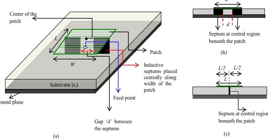
In order to alleviate the lacunae in those structures, a new technique is proposed where a pair of simple thin metal plate has been introduced beneath the patch cen-trally along the width of the patch as shown in Figure1.
This pair of simple thin metal plate produces an inductive discontinuity along the central region below the patch and hence acts as inductive septums. Unlike the previous structures we have introduced the reactive loading be-neath the patch instead of giving it to the patch. This has been done with a view to generate a new resonant mode while the usual dominant TM10 mode is kept unaltered. The proposed structure has been conceived based on the conjecture of producing new effective radiating slots (responsible for generating new resonant mode) along
with the actual radiating slots (responsible for generating traditional TM10 mode) by introducing the septums are justified quantitatively. A concrete mathematical back-ground behind the generation of new resonant modes along with traditional TM10 mode is presented. An easy and handful formulation has been established for calcula-tion of the frequency for new resonant mode as a func-tion of antenna parameters and the gap between the sep-tums. The detailed variation of resonant frequency of the new resonant mode as a function of the gap between the septums has been studied and presented in the paper. The proposed antenna can produce radiation along its broad-side direction for two individual frequency band with single polarization. The theory presented in the paper is successfully utilized to evaluate the behavior of such antenna which is verified using [13] and close agreement is revealed.
The novelty of the proposed antenna is to excite a new resonant mode with radiation characteristics similar to that due to fundamental dominant TM10 mode which can be justified quantitatively with concrete mathematical background. Moreover, the antenna exhibit dual band operation with polarization purity in its radiation charac-teristics for both the bands and its structure is very sim-ple and easy to manufacture.
The total work is analytically presented in the subse-quent sections. First we have discussed the proposed an-tenna geometry in Section 2 followed by the results ob-tained from the new antenna at Section 3. In the next section (Section 4), thorough quantitative analysis in the background of transmission line model and Transverse
Patch
Inductive septums placed centrally along width of the patch Substrate (εr)
Ground plane Center of the patch
Feed point
L
W
Gap ‘d’ between the septums
(a) (c)
Septum at central region beneath the patch
L L/2 L/2
W
(b)
Septum at central region beneath the patch
[image:2.595.86.515.475.697.2]d
Resonance Method is presented to explain the new find-ings from the proposed antenna.
2. Proposed Antenna Structure
A rectangular microstrip antenna with length L = 12 mm and width W = 18 mm for C band operation is shown in
Figure 1. A dielectric material of thickness h = 1.575
mm and relative permittivity of εr = 2.33 is utilized as
substrate. A pair of simple thin metal plate (inductive septums) has been introduced beneath the patch centrally along the width of the patch as shown in the figure. The gap between the septums d = 6 mm is as shown.
3. Results and Discussions
The input and radiation characteristics for the proposed antenna operating in C band is presented with the help of FEM based software tool [14].
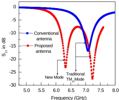
Figure 2 shows the complete return loss profile for
both the conventional antenna and the proposed one (both having same L, W and h values) which indicates clearly that there is a generation of new mode along with the tra-ditional TM10 mode in case of proposed antenna while this is not the case for conventional one. The conventional antenna resonates at 7.17 GHz with an impedance band-width of 2.8%, while the proposed antenna resonates at two individual frequency with 6.34 GHz and 7.24 GHz having 6% and 8% of impedance bandwidth respectively as revealed from Figure2. Using the formulation
devel-oped by one of the present authors [15] it is seen that the patch with L = 12 mm, W = 18 mm and h = 1.575 mm resonates at its fundamental dominant mode frequency of 7.2 GHz. Thus it confirms the development of new resonant mode at a frequency below the traditional fun-damental TM10 mode for the proposed antenna.
Figure3 shows the radiation pattern for E and H plane of
the proposed antenna for two separate frequencies. Fig-ure3(a) gives the radiation pattern at 7.24 GHz i.e. the
radiation fields associated with traditional TM10 mode where as 3(b) gives the radiation pattern at 6.33 GHz i.e.
the radiation fields associated with new mode. It may also be noted that for both the frequencies, radiations are in broad side direction as it should be for ideal dual band antennas. The gain for traditional TM10 mode is 7.2 dBi while that for new mode is 6.2 dBi. The comparison of
Figures 3(a) and (b) reveals that, the H plane cross
po-larized radiation associated with new resonant mode is slightly more than that of traditional TM10 mode while the co-polarized radiation pattern is nearly identical for both the frequencies. This slightly increased cross polar-ized radiation for the new mode does not hamper the antenna characteristic much but it may be minimized by cupping the ground plane as done in [16] for conven-tional microstrip antenna.
5.0 5.5 6.0 6.5 7.0 7.5 8.0 -30
-25 -20 -15 -10 -5 0
Proposed antenna
New Mode Traditional TM
10Mode S11
in
d
B
Frequency (GHz)
[image:3.595.326.518.86.247.2]Conventional antenna
Figure 2. Complete return loss profile for conventional an-tenna and proposed structure. Parameters: L = 12 mm, W = 18 mm, h = 1.575 mm, εr = 2.33, d = 6 mm and fed at 2.8 mm
from center of the patch.
-200 -150 -100 -50 0 50 100 150 200 -70
-60 -50 -40 -30 -20 -10 0 10
Radiation pattern for traditional TM
10mode (f = 7.24 GHz)
Gain
in
dB
Angle in degree
E plane H plane
(a)
-200 -150 -100 -50 0 50 100 150 200
-70 -60 -50 -40 -30 -20 -10 0 10
Radiation pattern for new mode (f = 6.33 GHz)
Gain in
dB
Angle in degree
E plane H plane
(b)
The effect of the separation between the septums d on the resonant frequency of new mode in case of proposed antenna has been presented in Table 1. It is evident from
the table that as the separation between the septums d
increases, resonant frequency of the new mode decreases. It should also be mentioned that, for other values of d
except d = 6 mm, the matching is poor and hence the gain of the antenna at new mode is degraded than that for traditional TM10 mode. This is the reason of choosing d = 6 mm for the proposed antenna.
4. Quantitative Analysis
When the very thin septums have been introduced un-derneath the patch along its width through central line (as in Figure1), it produces an inductive impedance of XL.
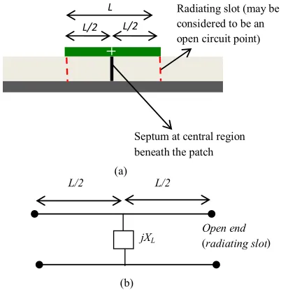
As this discontinuity under the patch is placed along the central region, it will not perturb the field distribution for dominant TM10 mode. Because, for that dominant TM10 mode, the field distribution underneath the patch is such that there will be a nodal point of electric field at the central region. Now, the radiating slots can be assumed to be an open circuit point because we know that, these are considered as magnetic walls in cavity model. The equivalent transmission line model is as shown in Figure 4.
Thus the resultant impedance (Zq) transformed from
these two radiating slots (open circuit points) at the cen-tral region will become parallel to the inductance pro-duced by septum XL in that region and hence producing
the equivalent impedance ZEat the central region below
the patch.
If we consider that the patch and ground plane as par-allel plate guide of characteristic impedance Z0 and the impedance transformed from each radiating slot (open circuit points) at the central region is Zs, then we may
write
0cot 2
s
Z jZ L (1)
2
0cot 2
2 2
s q
s
Z Z
Z j
Z
L (2)
As, ZE is parallel combination of Zq and jXL
q L
E
q L
Z jX
Z
Z jX
(3)
0
0
cot 2 2
cot 2 2
L E
L Z
j L j
Z
Z
j L jX
X
(4)
Following [17], if we apply Transverse Resonance Method (TRM) at the central region (where electric field node exists for TM10 mode) below the patch, we can write
Septum at central region beneath the patch
L
L/2 L/2
Radiating slot (may be considered to be an open circuit point
(a)
Open end (radiating slot)
L/2 L/2
jXL
(b)
)
[image:4.595.317.538.86.228.2]) (r
Figure 4. Cross-sectional view along the length (L) for pro-posed structure and its equivalent transmission line model (a) structural view; (b) transmission line equivalence.
Table 1. Variation of resonant frequency of new mode as a function of the gap between the septums d for proposed antenna compared with conventional antenna.
Conventional microstrip antenna with: L = 12 mm,
W = 18mm, h = 1.575 mm,εr = 2.33and fed at 2.8 mm
from center of the patch
Proposed microstrip antenna with: L = 12 mm,
W = 18mm, h = 1.575 mm,εr = 2.33and fed at
2.8 mm from center of the patch; d: variable
Gap between septums (d)in mm
10 TM
r
f GHz New
r
f GHz TM10
r
f GHz New
r
f GHz
4.0 7.24 6.56
4.6 7.22 6.50
5.0 7.23 6.46
6.0 7.24 6.34
7.0
7.17 No existence
[image:4.595.321.522.296.503.2]0
E
Z
(5)
0 0 cot 2 2 0 cot 2 2 L L Z
j L jX
Z
j L jX
(6)
This is possible if,
0cot 2 0
2 L
Z
j L jX
(7) Thus,
cotL 2 0 cot π 2 (7a)
π 2 g L
(8)
where λg is the wavelength within the dielectric.
Which is the primary requirement for the existence of dominant TM10 mode underneath the patch. Thus, it fur-ther confirms that the inductive septum placed under-neath the patch along its width at the central region which produces an inductive impedance of XL will not
affect the field distribution of dominant TM10 mode and hence radiation associated with this mode is kept unal-tered.
Now we may concentrate on the effect of inductive septum to produce the new resonant mode below the tra-ditional TM10 mode resonance. In fact, the effect be-comes prominent at a frequency other than TM10 mode frequency. In that case, the nodal point of electric field does not exist at the central region where septums are introduced. If we consider only one side of length L/2 (i.e.
from the central region towards one radiating slot) (see
Figure 4), at the central region beneath the patch, the
equivalent impedance due to one side 1 E
Z as
1 s L
E s L Z jX Z Z jX
(9)
as the impedance transformed from each radiating slot (open circuit points) at the central region is Zs. This is
basically the equivalent impedance at the central region below the patch due to parallel combinations of imped-ance transformed from one radiating slot (open circuit point) (as we have considered only one side) and the in-ductive impedance generated due to introduction of sep-tum at the central region.
Then using Equations (1) and (9)
0 0
cot 2 cot 2
L
L
Z L X
j X Z L
(10a)
0
1 0 cot 2 cot 2 L E L
j Z L X
Z
X Z L
(11)
which in fact, is capacitive in nature as observed from Equation (11). Now, if we consider this capacitance is developed at the input of an open circuited transmission line of length Δl, then we may write
0
1 0 0 cot 2 cot cot 2 L E L
j Z L X
jZ l Z
X Z L
(12)
Thus the effective position of the open circuit point is then located outward at a distance of Δl from the central region. Now using [18,19]
2 0 π tan 2 L g W X Z W d
(13)
Now with d = 6 mm, W = 18 mm we have
0 6 L g X Z
(14) Thus from Equations (12)-(14), we can write
0
00 0 0 6 cot 2 cot 6 cot 2 g g
j Z L Z
jZ l
Z Z L
(15)
cot 2
6cot
6 cot 2
g g L l L (16)
6 cot cot cot 2
6 cot 2 g g l l L L (17) Let,
cotL 2m (18) cot l n (19) Thus using (17)-(19)
6
g g
n mn m
6 (20)
0 1 0 cot 2 cot 2 L E LjZ L jX
Z
jZ L jX
6 6 1
g g
m n
(20a)
6 6
1
g g
m n
(21) Hence,
6 g 6 g
m n
m n
(22) cotL 2 cot l
(23) Thus
2
L l l L 2
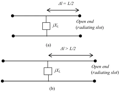
(24) Thus the effective position of the open circuit point (which may be assumed to be one radiating slot) is then located outward at a distance of Δl from the central re-gion and this is greater than the half of the length of the patch. Thus, the actual radiating slot in one side is at a distance of L/2 from the central region while another effective radiating slot is developed and the effective position of that new radiating slot in one side is at a dis-tance of Δl from the central region. The equivalent transmission line model for both the traditional TM10 mode and the new mode is as shown in Figure5.
Thus, considering both the sides, these two effective radiating slots are separated by 2Δl. This length is acting as a resonant length for a new resonant mode and thus a new mode has been generated. This new resonant mode radiates the electromagnetic wave through these effective radiating slots. However, the conventional dominant resonant mode TM10 kept unaltered as introduction of inductive septum does not affect the field distribution as explained earlier.
Now, from Equation (24)
2lL (25) Let, the resonant frequency of conventional dominant
Open end (radiating slot)
Δl = L/2
jXL
(a)
Open end (radiating slot)
Δl > L/2
jXL
(b)
t) (r
[image:6.595.73.274.547.697.2]t) (r
Figure 5. Equivalent transmission line model for traditional TM10 mode and new mode (a) traditional TM10 mode; (b) new mode.
resonant mode TM10 is TM10 and that for new mode
r
f
New r
f . Thus,
10
TM 2
r
f c L r (26)
New 2 2
r
f c l r (27)
Using Equation (25)
10
TM New
r r
f f (28) Thus the new mode with a resonant frequency lesser than that for traditional dominant TM10 mode is gener-ated with the proposed antenna.
Now, if the gap between the septums d increases, the resonant frequency of the new mode decreases. Let us consider two cases, where the gap between septums are
d1 and d2. The inductive reactances for those are XL1 and XL2 respectively.
Let, 1 2
Thus from Equation (13),
d d
2 2
1 2 1
tan πd 2Wtan πd 2W XL XL2 (29) where in the proposed structure, the gap between the septums is limited.
Thus,
1 0d W
1
π 2πd 2W 0 similarly;
2 0d W
2
π 2πd 2W 0
Thus recalling Equation (12) for these two cases,
1
1
1 0
cot 2 cot
cot 2
L
L
X L
l
X Z L
(30)
and
2
2
2 0
cot 2 cot
cot 2
L
L
X L
l
X Z L
(31)
dividing numerator and denominator of right hand side of Equations (30) and (31) by XL1 and XL2 respectively,
1
0 1
cot 2
cot
cot 2
1
L L l
Z L
X
(32)
2
0 2
cot 2
cot
cot 2
1
L L l
Z L
X
(33)
using (29)
1
1
l
l2 (35) Thus the two new effective radiating slots are sepa-rated by 2Δl1 which is smaller when the gap between septums are d1, compared to that when the gap between septums are d2. This confirms the observation of Table 1,
which show that, as the gap between septums increase, the resonant frequency of new resonant mode decrease.
Now in case of proposed antenna of L = 12 mm, W = 18 mm and the gap between the septum is d = 6 mm, Equations (18) and (19) gives,
cot 2 cot12π g
m L (36) using Equations (16), (19) and (36),
cot 2
6cot
6
cot 2
g
g
L
n l
L
Thus,
cot12π
66 cot12π
g g
g g
n
(37)
Using the formulation developed in (21),
6 6
1
g g
m n
now, putting the values from Equations (36) and (37) above equation results
6
6 cot12π
6
1
cot12π 6
cot12π
g g
g g
g
g g
(38)
which can be solved by numerical technique or graphical method and found to be satisfied for λg= 31.048 mm.
Thus, g r 47.39 mm and
New
6.33r
f c GHz for d = 6 mm which is in ex-cellent agreement with the simulated results as revealed from Figure2 and Table 1.
5. Conclusion
A rectangular microstrip antenna with centrally loaded inductive septums below the patch is proposed for dual band operation. The superiority of the proposed antenna to excite a new resonant mode below the conventional TM10 mode with faithful radiation pattern and apprecia-ble impedance bandwidth for both the bands is verified
along with concrete mathematical justification. A clear- cut and handful relationship has been established and successfully utilized for calculation of the frequency for new resonant mode for proposed antenna. This will be unquestionably helpful for the scientists, researchers and practicing engineers looking for such low profile antenna with dual band operation. The thorough mathematical analysis for the generation of new mode using such an-tenna is very supportive for future investigations in this area.
REFERENCES
[1] R. Garg, P. Bhartia, I. Bahl and A. Ittipiboon, “Microstrip Antenna Design Handbook,” Artech House, Norwood, 2001.
[2] S. Maci and G. B. Gentili, “Dual-Frequency Patch An-tennas,” IEEE Antennas and Propagation Magazine, Vol. 39, No. 6, 1997, pp. 13-20. doi:10.1109/74.646798 [3] J.-S. Chen and K.-L. Wong, “A Single-Layer
Dual-Fre-quency Rectangular Microstrip Patch Antenna Using a Single Probe Feed,” Microwave and Optical Technology Letters, Vol. 11, No. 2, 1996, pp. 38-84.
doi:10.1002/(SICI)1098-2760(19960205)11:2<83::AID-MOP10>3.0.CO;2-8
[4] Y. M. M. Antar, A. I. Ittipiboon and A. K. Bhattachatyya, “A Dual-Frequency Antenna Using a Single Patch and An Inclined Slot,” Microwave and Optical Technology Let-ters, Vol. 8, No. 6, 1995, pp. 309-310.
doi:10.1002/mop.4650080613
[5] J. S. Dahele, K. F. Lee and D. P. Wong, “Dual Frequency Stacked Annular-Ring Microstrip Antenna,” IEEE Trans- actions on Antennas and Propagation, Vol. 35, No. 11, 1987, pp. 1281-1285. doi:10.1109/TAP.1987.1143997 [6] J. Wang, R. Fralich, C. Wu and J. Litva, “Multifunctional
Aperture Coupled Stack Antenna,” Electronics Letters, Vol. 26, No. 25, 1990, pp. 2067-2068.
doi:10.1049/el:19901333
[7] W. F. Richards, S. E. Davidson and S. A. Long, “Dual- Band Reactively Loaded Microstrip Antenna,” IEEE Transactions on Antennas and Propagation, Vol. 33, No. 5, 1985, pp. 556-560. doi:10.1109/TAP.1985.1143617 [8] S. E. Davidson, S. A. Long and W. F. Richards, “Dual-
Band Microstrip Antenna with Monolithic Reactive Load-ing,” Electronics Letters, Vol. 21, No. 21, 1985, pp. 936- 937. doi:10.1049/el:19850662
[9] H. Nakano and K. Vichien, “Dual-Frequency Patch An-tenna with a Rectangular Notch,” Electronics Letters, Vol. 25, No. 16, 1989, pp. 1067-1068.
doi:10.1049/el:19890714
[10] J.-H. Lu and K.-L. Wong, “Slot-Loaded, Meandered Rec-tangular Microstrip Antenna with Compact Dual Fre-quency Operation,” Electronics Letters, Vol. 34, No. 11, 1998, pp. 1048-1050. doi:10.1049/el:19980737
[image:7.595.65.510.202.725.2][16] K. Malakar, J. Nandi, S. Mitra, P. K. Gorai, S. Chattopad- hyay, J. K. Sah and A. Anand, “Physical Insight into the Low Cross Polarized Radiation with Rectangular Micro-strip Antenna on Cupped Ground Plane,” International Journal of Electrical, Electronics and Computer Systems, Vol. 6, No. 2, 2012, pp. 1-5.
doi:10.1049/el:19971355
[12] K.-L. Wong and W.-S. Chen, “Compact Microstrip An-tenna with Dual-Frequency Operation,” Electronics Let-ters, Vol. 33, No. 8, 1997, pp. 646-647.
doi:10.1049/el:19970433
[13] X. L. Bao and M. J. Ammann, “Dual-Frequency Circu-larly-Polarized Patch Antenna with Compact Size and Small Frequency Ratio,” IEEE Transactions on Antennas and Propagation, Vol. 55, No. 7, 2007, pp. 2104-2107. doi:10.1109/TAP.2007.900271
[17] S. K. Ghosh, A. Ghosh, D. Ghosh, S. Chattopadhyay and S. Banerjee, “Rectangular Microstrip Antenna on Ridge Ground Plane to Control the Resonant Modes for Im-proved Bandwidth using Transverse Resonance Method,”
Journal of Electromagnetic Analysis and Applications, Vol. 4, No. 5, 2012, pp. 206-211.
doi:10.4236/jemaa.2012.45028 [14] “High Frequency Structure Simulator,” Ansoft Corp,
Version 10.
[15] S. Chattopadhyay, M. Biswas, J. Y. Siddiqui and D. Guha, “Rectangular Microstrips with Variable Air-Gap Varying Aspect Ratio: Improved Formulation and Experiments,”
Microwave Optical Technology Letters, Vol. 51, No. 1, 2009, pp. 169-173. doi:10.1002/mop.24025
[18] P. A. Rizzi, “Microwave Engineering: Passive Circuits,” Prentice Hall, Upper Saddle River, 1999.