© 2019, IRJET | Impact Factor value: 7.211 | ISO 9001:2008 Certified Journal
| Page 3482
Design and Analysis of Lumbar Spine using Finite Element Method
Mr. Sameer Pinjar
1, Dr. S N Kurbet
2, Mr. Pavankumar Hebsur
3, Mr. Suraj S Adavihal
41,3,4
M.Tech in Machine Design, Department of Mechanical Engineering, Basaveshwar Engineering College,
Bagalkot-587 102.
2
Professor, Department
of Mechanical Engineering, Basaveshwar Engineering College, Bagalkot-587 102.
Karnataka, India
---***---Abstract
-
One of the main part of the human body is spinalcord. The spinal cord include vertebrae, discs, and ligaments, all the three part gives flexibility of motion, protecting spinal cord and body force distribution. Here an effort is mad to design spinal cord with the help of catia and analysis is done through Ansys 14.5. The static forces are considered for the detailed analysis of lumbar spine L1 to L5. The age factor influence on bone properties and analysis is done by considering 40years aged bone properties, since mechanical factors played an important role in the onset of back pain, total deformation and Von-mises stress are studied in this project. On the basis of mechanical factor aim of the project is to study stress-strain field distribution of the spine under static load conditions forward and backward bend.
Key words: Finite element analysis, spine, modelling. 1. INTRODUCTION
The important part of the body is spinal cord. Spinal cord gives shape to body and also helps in motion. Spinal cord consists vertebra, disc, and ligaments works in combination to provides a motion protection and body force distribution. When the person or human under goes injury the equilibrium of vertebra, disc, and ligaments are distributed, and age the age factor also influence the efficiency of spinal cord and result chonic pain. The study of mechanical view helps to know the particular part isinfluenced by the gravitational overload of body and to prepare and design of suitable types of implants also necessary. And it is also helps know the resistance of spine by external loading is cause for lower back pain. The experimental studies of motion mechanical behavior shows age factor morphology postion and degeneration degree.[1]
2.
ANATOMY AND BIOMECHANICS
[image:1.595.316.542.223.435.2]The anatomy of spine is typical structure design to resist weight, and conjointly describe physiological movement and intense concern for the spine twine. The spine consists of vertebras and also the vertebras is combination of cortical bone and spongy trabucular bone. a complete of thirty three sorts of vertebras therein, five vertebras are united sacral, twelve vertebras are thoracic, seven vertebras are cervical, five vertebras are body part, three or four vertebras bone as shown within the figure2.1 [2]
Fig. 2.1 Human spine in lateral and posterior position [2]
2.1 Vertebras
Vertebrae are the thirty three individual bones that interlock with one another to make the spinal column. The vertebrae are numbered and divided into regions: cervical, thoracic, lumbar, sacrum, and coccyx. Solely the highest twenty four bones are transferable, the vertebrae of the sacrum and coccyx are fused. The vertebrae in every region have distinctive options that facilitate them perform their main functions. Parts of vertebras is created from completely different parts reminiscent of, Pedicles, Lamina, transverse and spinous method.
[image:1.595.339.512.623.743.2]© 2019, IRJET | Impact Factor value: 7.211 | ISO 9001:2008 Certified Journal
| Page 3483
2.2 Intervebral disc
Each vertebra in spine is separated and cushioned by an intervertebral disk, that keeps the bones from rubbing along. Discs ar designed sort of a radial tyre. The outer ring, known as the annulus, has crisscrossing brous bands, very like a tire tread. These bands attach between the bodies of every bone. Within the disc may be a gel-filled center known as the nucleus, very like a tire tube. Discs operate like helical springs. The crisscrossing bers of the annulus pull the os bones along against the elastic resistance of the gel-filled nucleus.
The nucleus acts sort of a roller bearing after you move, permitting the os bodies to roll over the incompressible gel. The gel-filled nucleus contains largely fluid. This fluid is absorbed throughout the night as you lie and is pushed out throughout the day as you progress upright. With age, our discs more and more lose the power to resorb fluid and become brittle and flatter; this can be why we have a tendency to get shorter as we have a tendency to get older.
Also diseases, akin to degenerative joint disease and pathology, cause bone spurs (osteophytes) to grow. Injury and strain will cause discs to bulge or herniate, a condition during which the nucleus is pushed out through the annulus to compress the nerve roots inflicting back pain.
3. WORKING SPINAL UNIT[2]
The working of spinal unit is contain 2 vertebras disc, two aspects of joint, and structures unified between vertebras. It’s one the necessary operating unit of spinal cord. To review and perceive the result of disease, degeneration inflammation and totally different spinal biomechanic. Disc provides six degree of freedom anmotion is restricted by fibers within the ligaments.
4. OBJECTIVES
1. To study the lumbar spine structure.
2. To design the lumbar spine from L1 to L5 with facilitate of Catia V5.
3. To perform finite part analysis of lumbar spine from L1 toL5.
4. To study the various boundary conditions that the lumbar spine goes below the deformation or inflammation.
5. Stress generation thanks to completely different load on adjacent vertebra segments and even be examined by finite element technique.
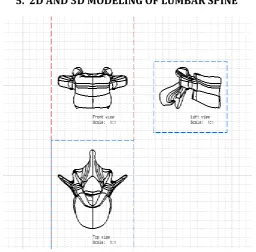
[image:2.595.305.562.261.513.2]5. 2D AND 3D MODELING OF LUMBAR SPINE
Fig. 5.1 2D lumbar spine
© 2019, IRJET | Impact Factor value: 7.211 | ISO 9001:2008 Certified Journal
| Page 3484
[image:3.595.41.286.262.418.2]Fig. 5.3 Lumbar spine side view
Fig. 5.4 Lumbar spine bottom view
6.
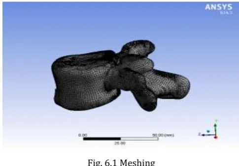
FINITE ELEMENT ANALYSIS
Fig. 6.1 Meshing
Moderate structural modulus of 233 ± 131 N/mm2
Ultimate compressive strength of 6.2 ± 3.4 N/mm2
Bone mineral densities of 385 ± 133 mg/cm3
Number of nodes 27310
Number of elements 27419
Fig. 6.2 Applied boundary condition
6.1 Finite element method
The 3D Fe model is generated wit facilitate of computed tomography for the Lumbar1(L1) to Lumbar2(L2) lumbar cluster is taken into account mechanical properties designed for five vertebrae, the four interverteral discs, the ligaments articular and capsular components, and funiculus.
The whole modeling supported a FEM that explaines the structure is in anatomical or not on basis of mechanical properties during this technique specification of load and pressure applied to it structure geometry of technique form and versatile properties applied of the part The geometry is another time devided into tiny components and therefore the differential equations regulate the deformation of solid ar numerically solved. The deformations gift thanks to totally different load condition.
The following ar the steps needed to finish the work.
1. explanation of geometry of the column organic components.
[image:3.595.41.284.470.639.2]© 2019, IRJET | Impact Factor value: 7.211 | ISO 9001:2008 Certified Journal
| Page 3485
3. Model examination by concluding a group of numerical calculation.
[image:4.595.40.282.454.581.2]7. RESULTS
© 2019, IRJET | Impact Factor value: 7.211 | ISO 9001:2008 Certified Journal
| Page 3486
7.1 lumbar spine at different loads.Graph 1:Comparision of total deformation at 10kg load
Graph 2: Comparison of equivalent stress at 10kg
Graph 3:Comparision of total deformation at 20kg load
Graph 4: Comparison of equivalent stress at 20kg
Graph 4:Comparision of total deformation at 30kg load
Graph 5: Comparison of equivalent stress at 30kg
8. CONCLUSION AND FUTURE WORK
8.1 Conclusion
Very important biomechanical things are fetched from results. The Von-misses stress at intervals the varied space of vertebras is plagued by the many form and size of the lumbar spine. It’s conjointly determined from a biomechanical purpose of read that least Von-misses stress and total deformation is knowledgeable about by spine5. The result's obtained are supported variable size and bone density. The results square measure controlled by some presumptions regarding the properties of materials and by the fundamental models used in FEM analysis. These result guide to picking the correct material and size of the implants which require to be wont to correct the imperfections and proper the defects. The utilization of screws known as pedicle screws will be chosen on the idea of study finished diameters and lengths.
8.2 Future works
Few diversifications will bring things smarter and advanced.
© 2019, IRJET | Impact Factor value: 7.211 | ISO 9001:2008 Certified Journal
| Page 3487
• Alternate screw thread will be designed to decrease the stresses and increase stability.
• More use of 3D modeling and prototypes of the lumbar spine to verify of suggests dimension to the pedicle screw.
References
1. Jozef Sumec, Milan Sokol,and Petra, 3 D FEM Analysis of Human Lumbar Spine in Extreme Positions, University of Saint Cyril and Methodius, Trnava, Slovakia.1-7
2. Rishikant Sahani, finite element analysis of human Lumbar vertebrae in pedicle Screw fixation,a thesis submitted in partial fulfillment of the requirements for the degree of master of technology,NITK Rourkela.
3. Salo, S., Leinonen, V., Rikkonen, T., Vainio, P., Marttila, J., Honkanen, R., & Sirola, J.(2014). Association between bone mineral density and lumbar disc degeneration. Maturitas, 79(4), 449-455.
4. Douchi, T., Kuwahata, R., Matsuo, T., Kuwahata, T., Oki, T., Nakae, M., & Nagata, Y. (2004). Age-related change in the strength of correlation of lumbar spine bone mineral density with other regions. Maturitas, 47(1), 55-59.
5. Sabo, M. T., Pollmann, S. I., Gurr, K. R., Bailey, C. S., & Holdsworth, D. W. (2009). Use of co-registered high-resolution computed tomography scans before and after screw insertion as a novel technique for bone mineral density determination along screw trajectory. Bone, 44(6), 1163-1168. 6. Singel, T. C., Patel, M. M., & Gohil, D. V. (2004). A
study of width and height of lumbar pedicles in Saurashtra region. J Anat Soc India, 53(1), 4-9. 7. Gocmen-Mas, N., Karabekir, H., Ertekin, T., Edizer,
M., Canan, Y., & Duyar, I. (2010). Evaluation of lumbar vertebral body and disc: a stereological morphometric study. Int J Morphol, 28(3), 841-847.
8. Zhou, S. H., McCarthy, I. D., McGregor, A. H., Coombs, R. R. H., & Hughes, S. P. F. (2000). Geometrical dimensions of the lower lumbar vertebrae–analysis of data from digitised CT images. European Spine Journal, 9(3), 242-248. 9. Ben-Hatira, F., Saidane, K., & Mrabet, A. (2012). A
finite element modeling of the human lumbar unit including the spinal cord.
10. Li, H. (2011). An Approach to Lumbar Vertebra Biomechanical Analysis Using the Finite Element Modeling Based on CT Images. INTECH Open Access Publisher.
11. Divya, V., & Anburajan, M., 2011, Finite element analysis of human lumbar spine. In Electronics Computer Technology (ICECT), 2011 3rd International Conference on (Vol.3, pp. 350-354). IEEE.
![Fig. 2.1 Human spine in lateral and posterior position [2]](https://thumb-us.123doks.com/thumbv2/123dok_us/9325829.434519/1.595.339.512.623.743/fig-human-spine-lateral-posterior-position.webp)