Bluetooth based Traffic Tracking System
ALWALEED KHALID
1, Dr. Irfan Memon
21
Student at Global Collage of Engineering and Technology, Muscat, Oman
2Lecturer at Global Collage of Engineering and Technology, Muscat, Oman
---***---Abstract -
With the limitations of satellite navigationsystems such as Global Positioning System (GPS) in indoor settings (tunnels, urban areas, etc.), alternative methods for vehicle tracking need to be developed for such settings. The aim of this project is to design a system that uses Bluetooth for traffic tracking. Bluetooth Low Energy modules, serve as beacons, placed along the road will have information about their position and they will constantly advertise this information to the passing vehicle. When the vehicle, which is attached with a Bluetooth module, passes by a beacon on the road the it will receive the position data and send it directly to the microcontroller. In turn, the microcontroller will send the data to be displayed on an LCD module and to an SD card to be processed later and compared with actual position data gathered from a GPS receiver.
Key Words: MATLAB, GPS, Indoor localization, Outdoor localization, IMU, Universal Asynchronous Receiver-transmitter.
1. INTRODUCTION
1.1. PROBLEM STATEMENT
Satellite navigation systems such as the Global Positioning System (GPS) provide an accurate and reliable positioning for vehicles in outdoor environments. Many studies have proven the significance of GPS in revolutionizing current practices of tracking and managing traffic in relatively open areas [1]. However, the application of GPS is hindered in highly dense urban areas and indoor settings due to the deflection and distortion of satellite signals by neighboring buildings which degrades the performance of GPS [1].
1.2. PROJECT INTRODUCTION
Lately, vehicle tracking techniques other than GPS have been developed for indoor situations such as methods based on Radio Frequency Identification (RFID), Bluetooth, and Wireless Local Area Networks (WLAN), etc. Other methods may involve using a system that integrates one of the techniques mentioned earlier with inertial measurement unit (IMU) for high precision.
The project is to design a traffic tracking system for indoor settings (tunnels, dense and complex urban areas, etc.) based on Bluetooth technology. The system will be able to identify the current position of a vehicle that has a Bluetooth module attached to it. The position data will be broadcasted by multiple Bluetooth Low Energy modules, that will serve as beacons, placed across the road. Whenever the vehicle passes by a beacon, the Bluetooth module on the car
receives the position data and passes it to the microcontroller to be analyzed. Kalman filter will be applied to the received data for more accurate results.
1.3. AIM
The aim of this report is to develop new indoor traffic tracking to improve positioning accuracy. There are some introduced indoor tracking systems. But, the rapid technology improvement open for us new way which might be more effective. Regrettably, there are no methods for indoor tracking is being approved. Yet, this thesis came to improve and prove that indoor traffic tracking system is important. Moreover, offering a new solution to assist mobility and security.
The purpose of this report is to design a system that uses Bluetooth for traffic tracking. This report proposes and evaluates the possibility of using a new approach to allocate traffic. Essentially, it will be done by providing the traffic with the most accurate latitude and longitude. The importance of being able to track the traffic in the indoor environment is to increase the matter of national security. The low energy Bluetooth uses low radio frequency which has a lower health risk to the surrounding individuals.
With large and wide indoor areas, the alternative indoor tracking becomes expansive. Significantly, this project offers a better solution including lower cost and efficiency. Bluetooth low energy (BLE) is cheaper to install and programming. Likewise, it costs low energy as it named low energy Bluetooth. Another key thing to remember, the channels provided by the BLE is 40 channels. In the other hand, the Wi-Fi tracking system as an alternative includes only three channels which have a bad effect gap that reduces tracking quality.
1.4. OBJECTIVES
Design, implement and evaluate an indoor traffic tracking system using low energy Bluetooth providing better accuracy. Design and proposed a method which is cheap to implement and carry out as a prototype. The implementation will be made by the smartest way to appear in great shape.
Use Bluetooth modules as beacons to advertise location for nearby traffic. Bluetooth act as aided localization system where it uses the electronics to allocate the traffic. The Bluetooth low energy (BLE) communication technology will broadcast a radio frequency in a low range. These signals will be received by the passing traffic. The Low range radio frequency (RF) of 40 channels signals will result in maximum location accuracy.
The attention command (AT command) to configure the universal unique identifier (UUID) of the Bluetooth modules. The AT command is used to configure the BLE to make it as master and slave mode. This is to get the possibility to establish the link. Furthermore, the media access control is also being configured for both as to make the connection possible. Could be a new smart fingerprint for the traffic. The proposed BLE have the ability to switch slave master mode making itself as a transceiver. However, the need for BLE is to advertise and so configuration of the slave is prepared.
Advertise the location data for the tracking system. The iBeacons will broadcast its location and it will do its job to evaluate the location by the distance. The Kalman filter will be used in this stage to ensure the estimation value is being calculated. The filter helps with the location accuracy comparing the values of the global positioning system (GPS).
Use a relatively inexpensive technology to develop a tracking system. Comparing the alternatives technology based on their accuracy, energy consumption and compatibility with the local environment. Alternative technology will be compared based on previous aspects. Bluetooth based traffic tracking could be the best smart low cost. It is cheap to implemented and maintain.
2. LITERATURE REVIEW
2.1. BACKGROUND
BLUETOOTH TECHNOLOGY Bluetooth is a radio protocol that operates in 2.4 GHz radio
band and used mostly for Personal Area Networks (PAN). It was Invented in Sweden by the phone company Ericsson. Bluetooth was based on an early wireless technology called MC-link which was intended to serve as a bridge to the worlds of PC and phone, providing a low power connection that is capable of handling audio and data [2].
Bluetooth standards were controlled, formally, by IEEE. However, they are managed now by the Bluetooth Special Interest Group (SIG). Bluetooth provides a link for data
[image:2.595.311.561.344.497.2]exchanging wirelessly between devices such as audio headsets, mobile phones, and keyboards. Bluetooth is classified, based on output power, to three classes. The characteristics of each class displayed in the table below.
Table -1: Characteristics of Bluetooth classes [3]
Range Power
Level Common Application
Class 1 100 meters 100 mW Laptop
Class 2 10 meters 2.5 mW Bluetooth
headsets
Class 3 1 meter 1 mW Keyboards
Bluetooth consists of multiple protocols and functions wrapped up in a stack as shown in the diagram below. It operates along the same band as 802.11b/g/n Wi-Fi, the 2.4 GHz ISM; although, there is no significant interference because of the low transmission power [4].
Fig -1: Bluetooth Protocol Stack [5]
Each Bluetooth device has a unique Media Access Control (MAC) address that can be recognized by communicating devices to initialize interaction when it is required. The MAC address is embedded by the manufacturer in the device’s hardware. The process of connecting Bluetooth devices follows three steps.
Firstly, discovery, when a slave module seeks other devices to link to by broadcasting its address and name. Secondly, pairing, when authentication and identification data are exchanged between master and slave modules, exploring the possibility of establishing a link. At last, connecting, when the master module finally establishes the link.
OVERVIEW OF BLUETOOTH LOW ENERGY Bluetooth Low Energy (or Bluetooth Smart) was developed
different technology than classic Bluetooth, with different design goals and different market segment although it based a lot of technology on its parent [7].
In order to communicate with its surroundings, a Bluetooth low energy device can use broadcasting or connecting mechanisms which are subjected to Generic Access Profile (GAP) guidelines [8]. GAP defines how BLE devices can interact with each other as well as how these devices make themselves visible to the outside world. GAP determines the roles of BLE devices, a device could be a peripheral or central.
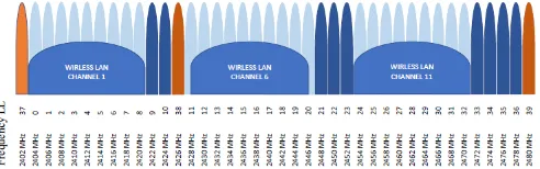
Central devices are usually the devices with higher processing power such as smartphones and tablets, whereas peripheral devices are low power and small devices that connect to a central device, these are like a heart rate monitor or a BLE-enabled beacon. There are three main channels for BLE to broadcast of which (39,38 and 37). These channels have been chosen as it does not crash with the Wi-Fi channels (11, 6 and 1). By this, we decreased the interference significantly. Figure 1 below shows the channels arrays for both Bluetooth and Wi-Fi.
Fig -2: BLE Channels
2.2. LITERATURE REVIEW
OVERVIEW OF KALMAN FILTER
The Kalman filter is one of the data fusion algorithms that are still being used commonly today. This is due to the small computational requirement of Kalman filter and its reputation as the optimal estimator for linear systems with Gaussian noise [3]. In Kalman filter model, it is assumed that the previous state of the system at time (k−1) determines the current state at time t according to the equation below.
(1)
Where (Xk) is the state vector which contains the values of interest. While (Uk) is the control input vector. Moreover, (Wk) is the process noise vector. In the other hand, (A) is the transition matrix. While (B) is the control input matrix. The measurement of the system is preformed based on the equation below.(2)
Where (Zk) is the measurement vector. While (H) is the transformation matrix. Moreover, (Vk) is the measurement noise. The measurement and process noise are independent of each other, assumed to be Gaussian with normalprobability distribution. Kalman filter uses some form of feedback control to estimate a process. The filter predicts the state of a process at time t and then obtains measurements as form of feedback. Therefore, the equations of Kalman filter are divided into two groups:
Time update equations they are responsible for projecting the current state ahead in time as well as the error covariance predictions to determine the priori estimates for next step.
Measurement update equations they are responsible for obtaining improved posteriori estimate by incorporating a new measurement into the priori estimate.
WSN-BASED LOCLIZATION APPROACH
Throughout the previous decade, a few of efforts has been made in developing reliable indoor tracking systems. One of the earliest efforts is the active badge tracker system developed by Roy in 2001 [9]. This system deployed numerous sensor nodes at fixed spots inside a building. The target person will wear an active badge, it works to transmits a unique code every quarter minute via an infrared sensor. The nodes of the sensor are viewed by a location manager for correction. This technique of centralized manager calculates the real position of the active badge and it provide location information to the users.
Alternative indoor tracking system is the cricket indoor tracking system [10]. The idea behind cricket that it uses anchors which broadcasts ultrasound pulse and radio messages. A mobile node will receive those messages and in return it calculates its own position. The results of this device show an incredible accuracy of 10 cm. unfortunately, these crickets are not practical due to the high mobile nodes cost.
RADAR is one of a kind that uses Wi-Fi signal for indoor localization systems [11]. It is constructed based on the fingerprint, in which the reference location is gathered during an offline period and compared with actual calculation during the online period. The result of the paperwork shows that RADAR technique localizes user’s laptops with an accuracy of 2m to 3m.
[image:3.595.41.287.364.441.2]Nonetheless, there is an interference caused by the magnetic sensor in the heading. Moreover, over time the emerging error increases significantly in which made the system ineffective. Additional approach is described by Liu in which the location is calculated based on the RSSI of a Wi-Fi and the fingerprint [1]. A main disadvantage of this approach is the huge variance of RSSI signals. This actually results in low reliability and low accuracy. Furthermore, this method is the overhead of utilizing databases in which takes long time to set up the database, specifically for enormous large buildings. A hybrid solution that fuses smartphone sensor measurements have been introduced because of the number of issues with the sensors. This technique uses Wi-Fi RSSI measurements [13]. This approach, a filter based on the Markov model is used for the fusion. The results of the system show it will be able to obtain an accuracy of about 1.5 meters.
DISCUSSION
[image:4.595.41.283.525.695.2]In conclusion, indoor localization systems mentioned above suffer from numerous drawbacks. The WSN-based approach has the disadvantage of in which people have to wear additional hardware. This makes the solution to be unfriendly. On the other side, the smartphone approach is more user-friendly. However, using smartphones sensors is not reliable because of huge error and the interference. Furthermore, linking the smartphone method with the fingerprint method for localization is more reliable and precise. However, the time required to set up the database is very long mainly for large buildings. Besides, the hybrid approach shows great accuracy. Although, BLE shows better accuracy then Wi-Fi as for RSSI-based measurements. To conclude, the table below lists the different technique in terms of the accuracy, advantages and disadvantages.
Table -2: Accuracy of different approaches [14] Solution Accuracy Advantages/disadvantages Active
badge Room size
- low accuracy - additional hardware
Cricket 10 cm
+ good accuracy - high hardware cost - additional hardware
RADAR 2-3 m
+low hardware cost - varying RSSI - database creation Smartphone
+ Internet
sensor 2-3 m
+ low hardware cost - emerging error - sensor interference
3. METHODOLOGY
3.1 PROJECT OVERVIEW
The main function of the system is to determine the current position of a vehicle using multiple BLE-enabled modules located along the road and act as beacons that broadcast the
position information to be received and interpreted by the microcontroller on the vehicle.
Each beacon is based on the HM-10 Bluetooth Low Energy module, designed by Jinan Huamao Technology Company which, in turn, is based on the Texas Instruments CC2541 System-on-Chip. The module can use the advertisement principle which allows the module, as a BLE device, to periodically broadcast data (position, for this project) to nearby devices. The module will be programmed using AT commands that will be send through using UART pins on the Arduino Nano (TX and RX).
The main part of the system consists of a microcontroller (ESP32) that represents the brain of the system along with a set of modules used to measure, receive, display and store position data. These modules are GPS, LCD, and SD card.
The GPS receiver module will measure the current position of the tracking system before a signal from a beacon is detected to simulate outdoor tracking, and once a beacon is discovered, the vehicle will rely on position data received from the beacon to perform indoor tracking. The position value recorded last from the GPS will be used as an initial value for Kalman filter. Although the vehicle will depend on the beacons for tracking, GPS will continue measuring the vehicle’s position in the background, so the values will serve as a reference for comparison against the position data received from the beacons.
The ESP32 board has a built-in Bluetooth Low Energy which enables it to receive data advertised by nearby devices. This will be exploited to receive position data from the beacons. The data will be processed and interpreted by the microcontroller. The received data will be stored in text file format in the SD card. The LCD will work to display the position data.
BLOCK DIAGRAM
[image:4.595.317.551.530.691.2] FLOW CHART
Fig -4: project flow chart
3.4 BEACON DESIGN
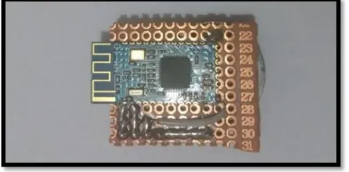
OVERVIEW Each beacon consists of a BLE module and battery holder that
holds the 3V battery that will power the module.
Fig -5: BLE iBeacon (front design)
Fig -6: BLE iBeacon (Back design)
BEACON DATA ADVERTISMENT To get the location data from the beacon, the ESP32
[image:5.595.39.287.83.463.2]microcontroller on the tracking system must receive the advertisement transmission from the beacon, identify the name of the beacon and read the latitude and longitude values embedded in the advertisement.
[image:5.595.310.556.89.267.2]Fig -7: Advertisement data broadcast by beacons [15]. The UUID (Universal Unique Identifier) is a 128-bit number stored in the Bluetooth devices used to identify a service. The UUID of the Bluetooth module is divided into four part (IBE0, IBE1, IBE2, IBE3), each one is 4-bytes long. These parts are configured individually through AT commands and they will be used to store the necessary data that will be transmitted to the tracking system. The functionality of each part of the UUID are chosen as such:
Table -3: UUID functionality.
UUID Function
IBE0 A unique hexadecimal value that it used to differentiate the beacons from other
Bluetooth devices. For this project, this value will be set to “4EB00215”.
[image:5.595.311.566.385.487.2] [image:5.595.37.289.583.707.2]IBE3 Hexadecimal value that identifies the location with respect to the
Equator and the Prime Meridian (North, South, East and West), as
shown in Figure 21.
The IBE3 part of the UUID is configured as such:
Table -4: Configuration of IBE3.
Location Hexadecimal value
IBE3
South, East 000F000F
North, East 000E000E
South, West 000D000D
North, West 000C000C
TX Power value (Figure 4) advertised by the module is hexadecimal value that represent the RSSI (Received Signal Strength Indication). This value is necessary to determine the proximity of the beacon to the tracking system. Therefore, the system will be able to identify the nearest beacon whenever there is more than one beacon available.
CONFIGURING BEACONS USING AT COMMANDS AT commands are simple instructions used to communicate
with certain devices. For this project, the commands will be used to communicate with the Bluetooth modules in order to configure them as beacons and assign the UUID to each beacon. Such configuration is done, first, by connecting TX and RX pins of the beacon to pins 8 and 9 of the Arduino Nano in order to establish UART communication.
Fig -8: Arduino UNO and Bluetooth module (iBeacon schematic diagram)
Configuring the beacons requires the program in Appendix to be uploaded to the Arduino board. The code works by sending the AT commands written in the Arduino IDE’s serial terminal to the Bluetooth module and displaying the commands on screen as well as the respond messages
from the module. Sending the command “AT+IBEx” followed by a 4-byte hexadecimal value assigns part ‘x’ of the UUID to the said value.
3.5 TRACKING SYSTEM DESIGN
[image:6.595.318.544.272.421.2]The system will function initially by tracking the location using the GPS module to simulate tracking in an outdoor environment. Then the GPS signal will be deactivated by pressing a button to allow the system to turn to Bluetooth to track its location. The system will scan for nearby beacons and receive the location data from the nearest beacon. The main components of the system are: ESP32 microcontroller, LCD module, SD card module, and GPS module. The connection between the components are show below.
[image:6.595.38.289.517.681.2]Fig -9: Schematic diagram of the tracking system The Bluetooth capability of ESP32 will allow the system to scan the area for nearby beacons. To display the location data, the LCD is connected to the microcontroller through 8 lines including ground and VCC. Those pins are connected to the microcontroller according to the following table:
Table -5: Nokia 5110 LCD module and ESP32 microcontroller pin assignment
Nokia 5110 LCD Module ESP32 Microcontroller
RST Digital pin 13
CE Digital pin 12
DC Digital pin 14
DIN Digital pin 27
CLK Digital pin 26
LIGHT GND (optional)
VCC 3.3V
GND GND
4. TEST AND DISCUSSIONS
4.1 INITIAL TESTING OF ONE BEACON
The aim of this is to test the method of configuring Bluetooth modules as beacons and their capability to advertise the data stored in them to other devices. As an initial test, a beacon will be assumed to contain the position data as follow:
Latitude: 1.533696˚N
Longitude: 110.368978˚E
Those values can be expressed as integers using the formulas explained in Section 3.4.3. The result will be as such:
(3)
(4)
Converting the values above into hexadecimal results in
(5)
(6)
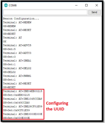
[image:7.595.309.564.192.310.2]Using AT commands, these values are assigned to the IBE1 and IBE2 parts of the UUID of the beacon. IBE0 part of the UUID is assigned the unique value of “4EB00215” and IBE3 is assigned to “000E000E”. The necessary commands used to configure the beacon are illustrated in the next page figure.
Fig -10: Configuring the beacon using AT commands The tracking system is supposed to scan the area for Bluetooth devices and identify the beacon from the value of IBE0 of the UUID, which is must be “4EB00215” as mentioned
in Table 3. This ensures that the device is a beacon and not any other Bluetooth device. Then the location data are extracted from the UUID of the beacon (IBE1 and IBE2) and convert the hexadecimal values back into decimal degrees using the code snippet displayed in Figure 27. In addition, the directions which are represented in the value of IBE3 will be identified and presented in the LCD screen along with the relevant data.
Fig -11: code snippet for converting hexadecimal location data into decimal
Fig -12: code snippet to determine the direction based on the IBE3 value.
[image:7.595.54.267.470.718.2]After the beacon is configured and the program given in Appendix A is uploaded to the ESP32 microcontroller, the serial terminal is expected to display the received UUID of the beacon. Besides, the LCD is expected to display the position data obtained from the UUID and converted into decimal degrees.
[image:7.595.330.530.582.769.2]The tracking system was able to receive the data broadcasted by the beacon and recover the data stored in its UUID. Figure 12 shows the hexadecimal values of the UUID parts are displayed and they are the same as the values that the UUID was configured with (as shown in Figure 13). Those values were converted back to their decimal degrees form and were displayed on the LCD screen of the tracking system as illustrated in the next figure.
Fig -12: first illustrated results of the project The converted latitude and longitude values are displayed on the LCD screen and they are nearly identical to the values assumed earlier in this section. The LCD shows that the directions are North and East for the latitude and longitude values respectively, which is identified from the IBE3 part of the UUID. This indicates that the system is capable of receiving the advertised data from the beacon and convert the hexadecimal data into decimal vales that can be interpreted as position data.
4.2 INITIAL TESTING OF TWO BEACON
When the tracking system discovers multiple beacons available nearby, it has to decide which beacon to receive the position data from. This is achieved by comparing the RSSI value of each discovered beacon. The RSSI value is negative and indicates the power level of the received signal. The further the beacon is from the tracking system, the higher is the absolute value of the RSSI. Therefore, when the tracking system discovers multiple beacons nearby, it will choose to receive location data from the beacon with the lowest RSSI value.
To test the system, two beacons are placed away from the tracking system at different distances. Beacon No.1 is placed nearer to the system than beacon No.2 and the system is supposed to scan the area and receive the data advertised by beacon No.1 since it is the one that is near to the system. Next, the position of the beacons will be reversed so that beacon No.2 is besides the tracking system.
The system will be forced to receive the location data from beacon No.2 rather than No.1. The program introduced in Appendix B, when uploaded to the microcontroller, will perform the aforementioned process and will display the RSSI values of the both beacons on the serial terminal of the Arduino IDE. The location data of the chosen beacon will be displayed on the LCD screen. The UUID of Beacon No.1 will
contain the data stored in the previous test, while beacon No.2 will contain the following information.
Latitude: 1.356897˚N
Longitude: 110.125478˚E
MATLAB KALMAN FILTER DESIGN The design of the Kalman filter will show both a study
state and time varying. In this code the output (y) will be estimating using noise measurement. The function of Kalman filter study state will be used. This function will determine the optimal steady state filter gain based on process noise. Below code shows the discrete plant and the input matrix.
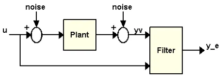
One of the things need to be noted that process noise must be a number greater than zero. The steady state filter holds two equation on it time update and measurement update. This is was easily done using the command (kalmf) in MATLAB. The first output of the Kalman filter represent the plant output estimate. Below figure shows how the filter work by generate data and compare it with true plant response.
Fig -13: Kalman filter work (MathWork, 2019) To simulate the system, we can generate the response of each part together or separately. In this case of project will simulate them together. The filter built in three input (u,v,w) and two inputs (y, yv). The code below illustrates the complete plant.
After that, the plant is connected with the Kalman filter in parallel this was done by making the input (u) as shared input. Finally, the plant output (yv) is connected to the filter input (yv). Code below shows connection between the plant and the Kalman filter.
[image:8.595.329.553.387.472.2]Fig -14: Kalman filter response
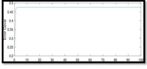
Fig -15: Error reduced by exact number
The error Covar shows it is only four or five simples it takes to reach it study state. After that, on the time varying the filter will have the same performance of the study state. Below two figures show the error covar and the measurement of the error covar.
[image:9.595.40.284.315.484.2]Fig -16: error covar verses samples
Fig -17: verify the steady state and final value These matrices are used as inputs for the prediction of the next time step. The steps will be repeated continuously for every position data received from the beacons. The tracking system is supposed to simulate tracking the position in outdoor environment by using GPS. The GPS module receives the location data repeatedly once every second as long as the button is not pressed. Pressing the button disables GPS tracking and switches to Bluetooth tracking.
Fig -18: Location of the beacons
5. CONCLUSION
Satellite navigation systems like the Global Position System have a huge disadvantage and noticeable limitations when it comes to tracking within indoor settings such as tunnels. Therefore, this project is intended to provide an alternative tracking method when the GPS signal is week or lost based on Bluetooth technology. The system was able to receive the advertised data from the beacon and convert the hexadecimal data into decimal vales that can be interpreted as position data. Furthermore, the system’s capability to receive the position data from the absolute nearest beacon was tested as well to ensure the accuracy of position of the system.
5.1 Further Work
During the system testing it was observed that occasionally the position estimation was inaccurate. Given that the user current position and the duration of the inquiry.
Reduced error
Final value
iBeacon two
[image:9.595.312.551.391.527.2] [image:9.595.35.285.586.704.2]For instance, when the user was close to a wall, the estimated position would occasionally be on the other side of the wall. Such cases could be avoided by making the system take the physical environment into account and exclude those impossible estimates. This would involve creating a model of the building which contains the possible paths to get from one point to another.
ACKNOWLEDGEMENT
I would like to thank Dr. Irfan amongst other UWE and GCET lecturers for providing the guidance and support through the project. Moreover, the academic adviser Dr. Javeed for his kind support in the software related issues that I have been throw. The lab technician staff Mohammed Al-Jabri for answering my technical questions quickly and comprehensively as well as supplying the parts for the project.
REFERENCES
[1] Lu, M., Chen, W., Shen, X., Lam, H.C. and Liu, J. (2007) Positioning and tracking construction vehicles in highly dense urban areas and building construction sites. Automation in Construction. 16 (5), pp. 647–656. doi:10.1016/j.autcon.2006.11.001.
[2] Nick, H. (2010) The Cambridge Wireless Essentials Series Series Editors A series of concise, practical guides for wireless industry professionals [online].[Accessed 10 November 2019].
[3] Peshin, A. (2019) what is the Range of Bluetooth? How Can It Be Extended? Available from: https://www.scienceabc.com/innovation/what-is-the-range-of-bluetooth-and-how-can-it-be-extended.html [Accessed 10 November 2019].
[4] Adam, L., Marcel, H. and Martin, H. (2015) Bluetooth enabled mobile phones and beyond. Available from: https://www.blackhat.com/presentations/bh-europe-05/bh-eu-05-trifinite-up.pdf [Accessed 10 November 2019].
[5] Adam, L., Marcel, H. and Martin, H. (2005) Hacking Bluetooth enabled mobile phones and beyond. Available from: https://www.blackhat.com/presentations/bh-europe-05/bh-eu-05-trifinite-up.pdf [Accessed 9 November 2019].
[6] Bahl, P. and Padmanabhan, V.N. (2000) RADAR: An in-building RF-based user location and tracking system. In: Proceedings - IEEE INFOCOM. 2000 (no place) IEEE. pp. 775–784. doi:10.1109/infcom.2000.832252.
[7] Blackstone, A. (2015) Understanding the different types
of BLE Beacons. Available from:
https://os.mbed.com/blog/entry/BLE-Beacons-URIBeacon-AltBeacons-iBeacon/ [Accessed 10 November 2019].
[8] Brockett, R.G. and Hiemstra, R. (1991) Self-Direction in Adult Learning: Perspectives on Theory, Research, and Practice. Routledge Series on Theory and Practice of Adult Education in North America. New York: Routledge.
[9] Component101 (2018) HM-10 Bluetooth Module Pinout, Features, Interfacing & Datasheet. Available from:
https://components101.com/wireless/hm-10-bluetooth-module [Accessed 10 November 2019].
[10]Digicore Australia (2015) What does GPS mean? | Digicore Australia. Available from: https://digicore-australia.com.au/faq/what-does-gps-mean/ [Accessed 10 November 2019].
[11]Faragher, R. (2012) Understanding the basis of the kalman filter via a simple and intuitive derivation [lecture notes] IEEE Signal Processing Magazine 29 (5) p.pp. 128–132. doi:10.1109/MSP.2012.2203621.
[12]GPS (2017) GPS. – Explaining Science. Available from: https://explainingscience.org/2017/01/29/gps/ [Accessed 10 November 2019].
[13]Gutierrez del Arroyo, J., Bindewald, J., Graham, S. and Rice, M. (2017) ENHANCING CRITICAL INFRASTRUCTURE SECURITY USING BLUETOOTH LOW ENERGY TRAFFIC SNIFFERS AIR FORCE INSTITUTE OF TECHNOLOGY.
[14]Haines, B. (2010) Seven Deadliest Wireless Technologies Attacks [online].[Accessed 10 November 2019].
[15]Harrison, R. (1978) How to Design and Conduct Self-Directed Learning Experiences. Group & Organization Studies [online]. 3 (2), pp. 149–167. Available from: http://journals.sagepub.com/doi/10.1177/105960117 800300203doi:10.1177/105960117800300203 [Accessed 10 November 2019].
BIOGRAPHIES
ALWALEED KHALID
![Table -1: Characteristics of Bluetooth classes [3]](https://thumb-us.123doks.com/thumbv2/123dok_us/9303494.430977/2.595.311.561.344.497/table-characteristics-of-bluetooth-classes.webp)
![Table -2: Accuracy of different approaches [14]](https://thumb-us.123doks.com/thumbv2/123dok_us/9303494.430977/4.595.41.283.525.695/table-accuracy-of-different-approaches.webp)