G. A. Aggidis* and C. J. Taylor1*
* Engineering Department, Lancaster University, Gillow Avenue, Lancaster, England, LA1 4YW (1Corresponding author: e-mail: [email protected])
Abstract: The first part of the article provides an overview of both single-axis and multi-axis wave energy converter (WEC) technology, with a particular focus on present and past prototype devices. The second part of the article considers a multi-axis concept device that has been developed and tank tested at Lancaster University by successive Master of Engineering project teams. TALOS is a point absorber-style device, built as a 1/100th scale representation, with a solid outer hull containing all the moving parts inside. The internal power take-off system is made up of an inertial mass with hydraulic cylinders, which attach it to the hull. The mass makes up a significant proportion of the mass of the device, hence it moves around as the hull is pushed by various wave motions i.e. an inertial mass power take-off approach. The latest design has proven to be successful in wave tank testing, in that the power take-off system yields a smooth output in response to time varying inputs from the waves. An analytical model was developed to combine data from the hull model and hydraulic rig, yielding a predicted power output of up to 3.2 kW.
Keywords: Power and Energy Systems (TC 6.3); Marine Systems (TC 7.2).
1. INTRODUCTION
Wave energy has significant potential to contribute to the attainment of energy targets through the production of clean, renewable energy. It is estimated that global near-shore energy resources are around 1-2 TW. Europe is classified as having a particularly large amount of available energy, with some of the highest power found off the shores of Ireland and Scotland, which can reach ~70 kW/m (Pontes, 2004). For example, Islay LIMPET off the north west coast of Scotland was the first commercial wave power device connected to the National Grid in the UK, with the initial prototype constructed in 1991 (Whittaker et al., 2004). It is estimated that the UK’s wave climate has the potential to provide up to 50 TWh/annum. In comparison to the UK’s annual usage of electricity in 2012, 317.5 TWh (Walters et al., 2015), this is clearly a significant proportion of energy.
Much research has focused on the point absorber type of Wave Energy Converter (WEC). Such devices possess relatively small dimensions compared to the incident wavelength of the wave. Examples include AquaBuOy (AquaBuOy, 2016), Powerbuoy (Powerbuoy, 2016) and Lancaster University’s PS Frog (Taylor et al., 2002; McCabe
et al., 2006). Other types of WEC include, for example, attenuators, point oscillating wave surge converters, oscillating water columns and terminators. Prototypes have included Oregon Limited’s multi resonant chamber (Orecon, 2009), Salter’s Duck (Salter, 1974), the Archimedes Wave Swing (AWS Ocean, 2016) and various Carnegie Wave Energy Limited prototypes (Wave Hub, 2016), among others. These examples and, in fact, the vast majority of WECs across the world, are single axis devices i.e. they extract energy from one direction of motion. Of course, the energy in
ocean waves is made up of kinetic and potential energy that act in multiple directions. Fig. 1 shows the six directions of motion from which energy can be captured i.e. there is a translational and rotational motion associated with each of the x, y and z axis. Hence, in total there are six degrees of freedom associated with bodies affected by wave motion. The directionality of waves varies depending on tides and the weather, meaning that a device which works in multiple axis should be able to generate power more consistently than most single-axis devices.
However, with a few notable exceptions, there are relatively few projects looking into multi-axis WECs, and there are only a few practical examples in existence. One of the best-known is Pelamis, based on a snake-like design with several tubes that are connected by hydraulic rams. The device works in a similar manner to an attenuator, facing into the direction of wave propagation. The relative motion between the sections of the device generates electricity through the hydraulic rams. Large scale prototypes have been deployed off the coast of Scotland and Portugal, and have fed electricity into the respective national power grids of each country (Boyle and Duckers, 2012).
Figure 1. Six degrees of freedom of a floating body (from Bhatt et al., 2016).
The present article reviews some of the literature and research issues for both single-axis and multi-axis WECs, with a particular focus on present and past prototype devices. It is an invited article for a special session on wave energy systems modelling, control and estimation. The second part of the article introduces the TALOS concept device that has been developed and tank tested by successive Master of Engineering project teams at Lancaster University (Osborne
et al., 2015; Bhatt et al., 2016), under the supervision of the present first author. TALOS is a multi-axis point absorber-style device, built as a 1/100th scale representation in order to be tested in the University’s wave tank.
2. WAVE ENERGY CONVERTERS
The majority of WECs across the world are single axis devices, and can often be categorised into attenuators, point absorbers, oscillating wave surge converters, oscillating water columns, terminators or submersed pressure differential devices. An attenuator operates in parallel to the direction of wave propagation. They generally have an elongated design, such that the length of the device spans approximately one wavelength (Seymour, 1992). Examples include the McCabe Wave Pump (Brooke, 2003) and Checkmate Sea Energy’s Anaconda (Checkmate, 2016). The latter is based on a rubber tube which contains a fluid. As waves propagate, they move sections of the rubber tube up and down. As this happens, the fluid inside the tube is pulled to the lowest parts of the tube due to gravity, causing the flexible rubber tubing to bulge. As this fluid moves, it is pressurised by gravity and the force of the flexible tube pressing on it. This pressurised fluid turns a hydraulic turbine, generating power (EMEC, 2016).
A point absorber possesses relatively small dimensions compared to the incident wavelength (Folley et al., 2004). Typically, the device floats on the water surface and heaves up and down. Alternatively, they are submerged beneath the surface to utilise the pressure differential. Examples include AquaBuOy (AquaBuOy, 2016), Powerbuoy (Powerbuoy, 2016) and PS Frog (Taylor et al., 2002; McCabe et al., 2006). PS Frog is a heaving device developed by Lancaster University, consisting of low mounted ballast and a large buoyant vertical paddle. An oscillatory motion is created by an oncoming wave, causing a high force on the vertical paddle leading the device to rotate clockwise. Once the wave has passed, the device rotates anti-clockwise back into its original position due to the opposing moment of the ballast. By contrast, oscillating wave surge converters are large paddles positioned perpendicular to the predominant wave direction, either fully or partially submerged in water (Folley
et al., 2004). They can be hinged at the top or bottom so that the paddle rotates about an axis parallel to the wave crests. An example is Oyster (Aquamarine Power, 2012), which is fixed at depths from 10 to 15 m and is intended to be positioned around 0.5 km from shore.
Oscillating water columns are arguably closer to full commercialisation than most other WEC technologies. Notable development sites include those on the islands of Islay off the Scottish west coast and Pico in the Azores (Cruz, 2008). They are generally comprised of a chamber containing a water column and air; a turbine to let air in and out of the chamber; and a front wall to allow the incident waves to raise and lower the water column. They work by using the rising and falling of the water column due to incident waves to compress and rarefy the air in the chamber, forcing the air through a bidirectional turbine to generate electricity (Webb
et al., 2005). Examples include LIMPET (Whittaker et al., 2004) and Orecon Limited’s multi-resonant chamber (Orecon, 2009). However, the latter project ran into commercial difficulties and their venture capitalists pulled out before manufacture began (Berkeley, 2016).
Terminator devices are orientated so that their principal axis is aligned perpendicular to the prominent direction of the oncoming waves and are positioned parallel to the wave front i.e. to physically intercept the waves (Drew et al., 2009). Examples include Salter’s Duck developed by Stephen Salter at Edinburgh University (Salter, 1974) and the Wave Dragon, developed in Demark and tested off the Pembrokeshire coast in Wales. Finally, submersed pressure differential devices have close similarities to point absorbers but operate in a fully submerged state. Examples include the Archimedes Wave Swing (Seymour, 1992), the prototypes under development by Carnegie Wave Energy Limited (EMEC Orkney (2016) and the viscoelastic artificial carpet device under development at the University of California Berkeley (Berkeley, 26).
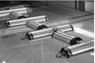
The above are single axis devices. As noted in section 1, there are relatively few examples of multi-axis devices, with Pelamis being one well-known exception. Another example is the device developed by Sam Etherington that won the James Dyson engineering prize (Ward, 2013). However, limited technical information about this device is available. It appears to function as an attenuator, using hydraulics to capture wave energy and convert it into electrical energy. In this manner, the device seems to take elements from both Salter’s Duck and Pelamis. In fact, a scale model was tank tested at Lancaster University, as illustrated in Figure 2.
[image:2.595.351.509.629.734.2]3. RESEARCH CHALLENGES
Selected issues of critical importance to WEC design include the power take-off system; control and optimisation; survivability (e.g. corrosion and impact resistance); mooring, power transfer and electrical grid interfacing; manufacture and logistics; environmental impact; and legislation (Bhatt et al., 2016). In the most general terms, control and optimisation aims to improve the year round productivity, efficiency in all sea states, and reduce the cost per kWh of electricity produced. Effective control strategies seek to increase the amount of energy that can be harnessed in low sea states, smooth out power fluctuations and provide a stable power output for the grid. However, optimising the amount of energy that can be absorbed from the sea poses a significant challenge, as discussed below.
As a result of continually changing sea states and seasonal variation in the wave climate, the efficiencies of WECs tend to be very low. Hence, effective control is essential for cost effective harnessing of wave energy (Korde, 2000; Drew et al., 2009). One well-known approach is latching, which aims to keep the velocity of the device in phase with the excitation force provided by the incident waveform. When the motion starts to deviate from the phase of the dominant wave the motion is locked (Salter et al., 2002). For the opposite of latching, called unlatching or declutching, the moving element freely oscillates for part of the cycle, with the power-take off (PTO) mechanism only being engaged when the velocity is close to what is desired in order to achieve greater efficiency. By contrast, reactive loading and phase control involves adjusting the dynamic parameters (such as the spring coefficient, damping and inertia) of the WEC to enable maximum power absorption (Salter et al., 2002).
A PTO system is required to transform the multi-directional kinetic energy present in waves into electricity. In the vast majority of cases, this is achieved by applying a force that causes the rotation of a mechanical element, thereby powering an electrical generator (Brooke, 2003). The three most common WEC PTO systems are turbines, linear generators and hydraulics (Drew et al., 2009). Turbines are used in WECs to convert the motion of waves into rotational kinetic energy in order to drive the generator. The two prominent types of turbine used in this context are air turbines, commonly found in oscillating water columns, and water turbines used, for example, in overtopping devices such as the Wave Dragon (Wave Dragon, 2016). However, generating electricity from ocean waves generally involves capturing energy from slow moving waves, which transfer large forces. Hence, high-pressure oil-hydraulic PTO systems are particularly well suited to many other types of WEC, including the TALOS device considered later.
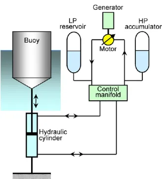
Figure 3 shows a hydraulic PTO system (for clarity of explanation this schematic is based on a simple heaving buoy WEC). As the double acting hydraulic cylinder moves, it drives pressurised fluid around the circuit, causing rotation such that the generator is driven, producing electricity. This circuit also features a control manifold, and low pressure and high pressure accumulators. These components are utilised when smoothing the output to the generator.
[image:3.595.350.514.87.268.2]Figure 3 Hydraulic PTO System Operating in Heave (from Bhatt et al., 2016).
Figure 4 TALOS I photograph (left) and TALOS II
prototype diagram, with cut away section to show the internal PTO components (from Bhatt et al., 2016).
4. TALOS II DEVELOPMENT
The TALOS device is a part of an ongoing process of research and development into wave energy conversion at Lancaster University. It is a multi-axis point absorber-style device, with a solid outer hull containing all the moving parts inside. The initial TALOS I device, shown as the left hand side image in Figure 4, is a 1/100th scale representation (based on an actual device width of about 60 m, although this would depend on the deployment location). Osborne et al. (2015) develop and investigate the TALOS I device, while Bhatt et al. (2016) consider a second iteration of its design, TALOS II. An image of the exterior of TALOS II, with a cut out to show the PTO system, is also shown in Figure 4.
[image:3.595.308.550.303.437.2]multiple directions, allowing energy to be captured from multiple degrees of freedom. The flow of hydraulic fluid will change as the ball’s motion changes, so an internal hydraulic smoothing circuit is utilised to regulate the output of the device. Selected development work is briefly reviewed below, focusing primarily on TALOS II.
4.1 Structural and Hydrodynamic Development
The shape and structure of the hull determines the magnitude and frequency of the acceleration and is linked to overall efficiency. This is particularly important for an inertial mass PTO, as used here. Hence, the geometry of TALOS II is optimised by Bhatt et al. (2016) through the use of ANSYS AQWA simulations, with three aims as follows: (1) to optimise the geometry of TALOS I, for comparison purposes, whilst maintaining a similar octagonal mushroom shape; (2) to develop similar shapes to TALOS I, whilst allowing a greater degree of variety within the geometry; and (3) to investigate innovative unique shapes. The models were created in Solidworks for import into ANSYS AQWA. The hull was meshed to a ‘medium’ degree, before being placed in a 10 m x 10 m square, 2 m deep sea. These dimensions create an environment which is broadly similar to the Lancaster wave tank in which it is later physically tested.
Jacobian ratios, skewness and aspect ratios are checked to ensure they are within suitable ranges. Mesh refinement is otherwise conducted to bring them to suitable values. A hydrodynamic diffraction analysis is used to view how the hull responds to varying wave conditions of differing amplitudes and frequencies. This allows for a visual representation of how the body will move within the wave, as well as the pressure distributions of the refraction of the wave. The ANSYS AQWA simulations are comprised of a time-response analysis lasting 30 s. The structure is free to move and the process is repeated for high and low sea states.
Using an iterative process to investigate various candidate shapes, including TALOS I from Figure 4, variations on TALOS I such as 3 and 12 sided, and other shapes including pear, cylinders, triangular and square mushrooms, acorn, inverted triangular pyramid, etc., the optimisation process demonstrates the advantageous hydrodynamic properties inherent in triangular bodies, particularly those which have a large freeboard cross sectional area, and a smaller draft cross sectional area. The addition of fins, as indicated in Figure 4, when used on such a triangular body, can further increase the RAO acceleration significantly. Bhatt et al. (2016) provide a complete list of dimensions for the optimised TALOS II hull shape, with mass, centre of mass location and RAO accelerations in response to a Pierson Moskowitz wave spectrum also stated. These are omitted for brevity here, but Figure 4 is indicative of the shape that has been optimised for the Lancaster University wave tank.
4.2 Wave Tank Testing
The wave tank is designed to test models at a scale of 1:100. The tank is capable of generating sine waves at frequencies between 0.25 Hz and 1.75 Hz, at a range of different amplitudes. In addition to this, specific waveforms can be programmed and loaded onto the wave tank controller
software. For the purpose of the present tests, the only waveforms that were used other than sine waves were the ones already pre-loaded on the software. The most useful of these was the Pierson-Moskovitz spectrum, a spectrum which is used to define the behaviour of waves in an open ocean. The tests are intended as a way of analysing the performance of TALOS I and II, while optimising the configuration. However, there are theoretically an almost infinite number of different configurations. Therefore, the tests were chosen to represent a broad range of illustrative options. In future research, the most effective should be further adjusted to fine-tune the performance of the device.
[image:4.595.318.535.514.742.2]The original TALOS I design featured four dampers, and had a circuit designed to log data from these four positions. By contrast, for the experiments on TALOS II, the maximum number of dampers was set to six, with tests being carried out with configurations of four, five and six dampers. An Arduino Uno was utilised to log the positions of the potentiometers by reading the voltage across the connections. Various configurations of damper arrangement (e.g. angle), damping amount, spring stiffness and ball mass were investigated in these experiments.
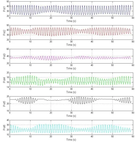
Figure 5 shows an illustrative test result for the device in the wave tank, based on a layout with three dampers on the top and three on the bottom of the device. In Figure 5, Pot1, Pot2 and Pot3 represent the upper potentiometer displacements, while Pot4, Pot5 and Pot6 are the lower ones. Pots 1 and 2 vary the most, with amplitudes of around 7.5 mm at their peak, whereas Pots 4 and 5 vary with much smaller amplitudes of roughly 2 mm. This could suggest that the ball is supported by the pre-compressed springs on the bottom of the ball, and is therefore rocking around in a manner that resembles an inverted pendulum. The lower harmonic of potentiometer amplitudes is offset, which would be beneficial to a full-scale PTO smoothing circuit. However, more research into why some potentiometers vary more than others needs to be conducted.
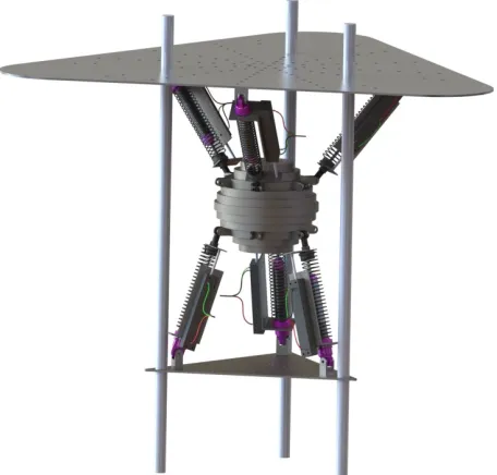
Figure 6 TALOS II damper configuration (from Bhatt et al., 2016).
Nonetheless, from the various configurations examined to date, one particular set of damper angles and positions, and associated relative position of the ball, based on using six dampers as illustrated in Figure 6, is determined to yield the best performance. Here, performance is straightforwardly defined as the configuration that yields the greatest total displacement of the potentiometers. When the potentiometers are replaced with hydraulic cylinders, this is theoretically proportional to the amount of fluid which would be pumped per unit time. To conclude, the testing of both TALOS I and TALOS II shows how important the damping configuration is to its overall performance. Even subtly different setups led to significantly improved or compromised performance. When further work is carried out with larger scale prototypes, it will be essential to ensure these interior components are similarly configured and optimised.
4.3 Power Take-Off System Development
Hardware prototypes that interface with National Instruments Labview software have been built and investigated, with Figure 7 showing the various components set out in the laboratory. Research into the hydraulic smoothing circuit, for example, aims to reduce the fluctuation of the input flow and provide a constant output flow of hydraulic fluid, by means of hydraulic accumulators. A smooth output flow from the system means that the generator will rotate with minimal changes in speed; as a result the electrical power produced will have minimal fluctuations.
[image:5.595.306.550.71.245.2]Control challenges include observed nonlinear behaviour of the flow turbine sensors, phase shifts between the desired inflow to the accumulators and the measured inflow; dynamic behaviour exhibited by the valve; and the fact that different control gains are needed whenever a system variable is changed. Research is also required to maximise energy absorption by introducing control methodologies for the back pressure and accumulator charge.
Figure 7 PTO circuit set out in the laboratory for testing (from Bhatt et al., 2016).
Figure 8 Simulink model of the generator circuit subsystem (from Bhatt et al., 2016).
A Matlab/Simulink model that replicates the hydraulic circuit has been developed and validated against the laboratory system. Figure 8 illustrates one of the subsystems for this model. Wave tank data is fed into the model to provide a representative approximation of the dynamics of the combined physical input and smoothing circuit rig. This approach yields a fluid power of 3.2 kW at 125 bar and 15 L/min measured at the outlet of the smoothing circuit. The model provides a proof of concept of the current PTO system, whilst the physical system is under development.
5. CONCLUSIONS
[image:5.595.53.281.73.291.2] [image:5.595.304.555.261.458.2]ACKNOWLEDGEMENTS
The authors are particularly grateful to J. Bhatt, J. Carthy, T. Clark, S. Galea, A. Sutch, A. Tutt and J. Walker for their work on TALOS II, as reported in this article.
REFERENCES
AquaBuOy (2016)
http://www.global-greenhouse-warming.com/Finavera-aquabuoy.html
[Accessed 29 October 2016].
Aquamarine Power (2012) Lewis Wave Power Limited, 40MW Oyster Wave Array North West Coast, Isle of Lewis, Vol. 1 Non-Technical Summary and
Vol. 2 Environmental Statement, North West Coast, Isle of Lewis,
http://77.68.107.10/Renewables%20Licensing/LWP_W est_of_Lewis_Offshore_Wavefarm/LWP_LTD_ES/LW P%20Ltd%20ES%20Volume%201%20-%20Non-Technical%20Summary/Vol1_Non_Technical_Summar y.pdf [Accessed 29 October 2016].
AWS Ocean (2016) Archimedes Waveswing Submerged Wave Power Buoy,
http://awsocean.com/technology/archimedes-waveswing-submerged-wave-power-buoy
[Accessed 29 October 2016].
Berkeley (2016) University of California, Berkeley, Theoretical and Applied Fluid Dynamics Laboratory, Wave Carpet: An Efficient and Multidirectional Ocean Wave Energy Converter, http://taflab.berkeley.edu/uc-berkeley-ocean-wave-energy-converter
[Accessed 29 October 2016].
Bhatt, J., Carthy, J., Clark, T., Galea, S., Sutch, A., Tutt, A. and Walker, J. (2016) Optimisation and Development of a Multi-Axis Wave Energy Converter Device, Master of Engineering Project Report, Engineering Department, Lancaster University.
Boyle, G. and Duckers, L. (2012) Renewable Energy: Power for a Sustainable Future, OUP Oxford.
Brooke, J. (2003) Wave Energy Conversion, Elsevier. Checkmate (2016) Checkmate Sea Energy
http://www.checkmateukseaenergy.com/anaconda
[Accessed 29 October 2016].
Cruz, J. (2008) Ocean Wave Energy - Current Status and Future Perspectives, Springer.
Drew, B., Plummer, A.R. and Sahinkaya, M.N. (2009) A review of wave energy converter technology,
IMechE Proceedings A, 223, pp. 887–902. EMEC (2016) EMEC Orkney Wave Devices
http://www.emec.org.uk/marine-energy/wave-devices
[Accessed 29 October 2016].
Folley, M., Whittaker, T. and Osterried, M. (2004) The Oscillating Wave Surge Converter, School of Civil Engineering, Queen's University Belfast, UK. Fraser, D. (2014) Jobs go after no buyer found for Pelamis
wave business, BBC News,
http://www.bbc.co.uk/news/uk-scotland-scotland-business-30560980 [Accessed 29 October 2016].
Korde, U.A. (2000) Control System Applications in Wave Energy Converters, OCEANS MTS/IEEE Conference, DOI: 10.1109/OCEANS.2000.882202.
Marsh G. (2010) Maximising wave power, Renewable Energy Focus,
http://www.renewableenergyfocus.com/view/7435/max
imising-wave-power [Accessed 29 October 2016].
McCabe, A.P., Bradshaw, A., Meadowcroft, J.A. and Aggidis, G. (2006) Developments in the design of the PS Frog Mk 5 wave energy converter, Renewable Energy, 31, pp. 141–151.
Orecon (2009) Renewable Energy Focus, Wave energy developer Orecon hits stormy waters,
http://www.renewableenergyfocus.com/view/5700/wav e-energy-developer-orecon-hits-stormy-waters
[Accessed 29 October 2016].
Osborne, J., Rawcliffe, P., Tarrant, H., Wheatland, W., Lovett, M., Tailyour, J., Veryard, P., Woodall, A. and Jesson, P. (2015) Multi-Axis Wave Energy Converter, Master of Engineering Project Report, Engineering Department, Lancaster University.
Pontes, M.T. (2004) The Ocean: An Inexhaustible Renewable Energy Source? EurOCEAN, Galway, Ireland.
Powerbuoy (2016) Ocean Power Technologies
http://www.oceanpowertechnologies.com/powerbuoy-technology [Accessed 29 October 2016].
Salter, S.H. (1974) Wave Power, Nature, 249, pp. 720–724. Salter, S.H., Taylor, J.R. and Caldwell, N.J. (2002) Power
Conversion Mechanisms for Wave Energy, IMechE
Proceedings: Engineering for the Maritime Environment, 216, pp. 1–27.
Seymour, R.J. (1992) Ocean Energy Recovery: The State of the Art American, Society of Civil Engineers. Taylor, C.J., Bradshaw, A., Chaplin, R.V., French, M. and
Widden, M.B. (2002) Wave Energy Research at Lancaster University: PS FRog and Frond, World Renewable Energy Congress VII, Cologne, Germany. Walters, L., Goodright V. and Wilkes, E. (2015) Energy
Consumption in The UK 2015, Department of Energy and Climate Change.
Ward, M. (2013) Wave power generator bags Dyson award,
BBC News,
http://www.bbc.co.uk/news/technology-24070071 [Accessed 29 October 2016].
Wave Dragon (2016) http://www.wavedragon.net
[Accessed 29 October 2016].
Wave Hub (2016) Carnegie Wave Energy Limited,
http://www.wavehub.co.uk/wave-hub-site/our-customers/carnegie-wave-energy-limited
[Accessed 29 October 2016].
Webb, I., Seaman, C. and Jackson, G. (2005) Arup Energy Oscillating Water Column Wave Energy Converter Evaluation Report, The Carbon Trust, Marine Energy Challenge.
Whittaker, T.J.T., Battie, W., Folley, M., Boake, C., Wright, A., Osterried, M. and Heath, T. (2004) The Limpet Wave Power Project – The First Years of Operation,
https://web.sbe.hw.ac.uk/staffprofiles/bdgsa/shsg/Docu