RESEARCH ARTICLE
INTEGRATED SOLAR PV AND BATTERY STORAGE SYSTEM USING FIVE-LEVEL NPC INVERTER
FOR INDUCTION MOTOR APPLICATION
Preethi, L. and RamyaRani, N.
Department of EEE, SKCET, Coimbatore, India
ARTICLE INFO ABSTRACT
In this paper, a configuration of a five-level neutral point clamped (NPC) inverter that can integrate solar PV with battery storage and it is connected to the induction motor and vlf speed control is also proposed. This paper illustrates the design of three-port dc–dc converter for stand-alone PV systems based on an improved Flyback-Forward topology. It provides a compact single-unit solution with a combined feature of optimized maximum power point tracking (MPPT), high step-up ratio, galvanic isolation, and multiple operating modes for domestic, aerospace and for industrial applications.
Copyright © 2016, Preethi and RamyaRani. This is an open access article distributed under the Creative Commons Attribution License, which permits unrestricted use, distribution, and reproduction in any medium, provided the original work is properly cited.
INTRODUCTION
Demand for high-voltage, high power converters capable of producing high-quality waveforms while utilizing low voltage devices and reduced switching frequencies has led to the multilevel inverter development with regard to semiconductor power switch voltage limits. Multilevel inverters include an array of power semiconductors and capacitor voltage sources, the output of which generate voltages with stepped wave forms. The commutation of the switches permits the addition of the capacitor voltages, which reach high voltage at the output, while the power semiconductors must withstand only reduced voltages.
The most attractive features of multilevel inverters are as
follows:-1) They can generate output voltages with extremely low distortion and lower dv/dt.
2) They draw input current with very low distortion.
3) They generate smaller common mode (CM) voltage, thus reducing the stress in the motor bearings. In addition, using sophisticated modulation methods, CM voltages can be eliminated.
4) They can operate with a lower switching frequency.
The multilevel inverter has been implemented in various applications ranging from medium to high -power levels, such as motor drives, power conditioning devices, also conventional or renewable energy generation and distribution (Selvaraj and Rahim, 2009). The different multilevel inverter structures are cascaded H -bridge, diode clamped and flying capacitor multilevel inverter. Among the three topologies, the cascaded multilevel inverter has the potential to be the most reliable and achieve the best fault tolerance owing to its modularity, a feature that enables the inverter to continue operating at lower power levels after cell failure. Modularity also permits the cascaded multilevel inverter to be stacked easily for high power and high voltage applications. The cascaded multilevel inverter typically comprises several identical single phase H bridge cells cascaded in series at its output side. This configuration is commonly referred to as a cascaded H –bridge (Park et al., 2003), which can be classified as symmetrical if the dc bus voltages are equal in all the series power cells, or as asymmetrical if otherwise. In an asymmetrical CHB, dc voltages are varied to produce more output levels. There are mainly three types of multilevel converter (Selvaraj and Rahim, 2009), namely the neutral point clamped (NPC) converter, the flying capacitor (FC) converter and the cascaded H-bridge converter which are shown in Figure 1. The introduction of three-level NPC converter topology in early 1980’s has made
revolutionary changes in the utilization of power electronics in
ISSN: 0975-833X
International Journal of Current Research Vol. 8, Issue, 05, pp.30423-30429, May, 2016
INTERNATIONAL JOURNAL OF CURRENT RESEARCH
Article History:
Received 15thFebruary, 2016
Received in revised form 07thMarch, 2016
Accepted 06thApril, 2016
Published online 10thMay, 2016
Key words:
Battery storage, Solar photovoltaic (PV), Three port dc to dc converter,
Five-level NPC inverter, Induction motor, vlf control.
Citation: Preethi, L. and RamyaRani, N. 2016.“Integrated solar PV and battery storage system using five-level NPC inverter for induction motor
application”,International Journal of Current Research, 8, (05), 30423-30429.
RESEARCH ARTICLE
INTEGRATED SOLAR PV AND BATTERY STORAGE SYSTEM USING FIVE-LEVEL NPC INVERTER
FOR INDUCTION MOTOR APPLICATION
Preethi, L. and RamyaRani, N.
Department of EEE, SKCET, Coimbatore, India
ARTICLE INFO ABSTRACT
In this paper, a configuration of a five-level neutral point clamped (NPC) inverter that can integrate solar PV with battery storage and it is connected to the induction motor and vlf speed control is also proposed. This paper illustrates the design of three-port dc–dc converter for stand-alone PV systems based on an improved Flyback-Forward topology. It provides a compact single-unit solution with a combined feature of optimized maximum power point tracking (MPPT), high step-up ratio, galvanic isolation, and multiple operating modes for domestic, aerospace and for industrial applications.
Copyright © 2016, Preethi and RamyaRani. This is an open access article distributed under the Creative Commons Attribution License, which permits unrestricted use, distribution, and reproduction in any medium, provided the original work is properly cited.
INTRODUCTION
Demand for high-voltage, high power converters capable of producing high-quality waveforms while utilizing low voltage devices and reduced switching frequencies has led to the multilevel inverter development with regard to semiconductor power switch voltage limits. Multilevel inverters include an array of power semiconductors and capacitor voltage sources, the output of which generate voltages with stepped wave forms. The commutation of the switches permits the addition of the capacitor voltages, which reach high voltage at the output, while the power semiconductors must withstand only reduced voltages.
The most attractive features of multilevel inverters are as
follows:-1) They can generate output voltages with extremely low distortion and lower dv/dt.
2) They draw input current with very low distortion.
3) They generate smaller common mode (CM) voltage, thus reducing the stress in the motor bearings. In addition, using sophisticated modulation methods, CM voltages can be eliminated.
4) They can operate with a lower switching frequency.
The multilevel inverter has been implemented in various applications ranging from medium to high -power levels, such as motor drives, power conditioning devices, also conventional or renewable energy generation and distribution (Selvaraj and Rahim, 2009). The different multilevel inverter structures are cascaded H -bridge, diode clamped and flying capacitor multilevel inverter. Among the three topologies, the cascaded multilevel inverter has the potential to be the most reliable and achieve the best fault tolerance owing to its modularity, a feature that enables the inverter to continue operating at lower power levels after cell failure. Modularity also permits the cascaded multilevel inverter to be stacked easily for high power and high voltage applications. The cascaded multilevel inverter typically comprises several identical single phase H bridge cells cascaded in series at its output side. This configuration is commonly referred to as a cascaded H –bridge (Park et al., 2003), which can be classified as symmetrical if the dc bus voltages are equal in all the series power cells, or as asymmetrical if otherwise. In an asymmetrical CHB, dc voltages are varied to produce more output levels. There are mainly three types of multilevel converter (Selvaraj and Rahim, 2009), namely the neutral point clamped (NPC) converter, the flying capacitor (FC) converter and the cascaded H-bridge converter which are shown in Figure 1. The introduction of three-level NPC converter topology in early 1980’s has made
revolutionary changes in the utilization of power electronics in
ISSN: 0975-833X
International Journal of Current Research Vol. 8, Issue, 05, pp.30423-30429, May, 2016
INTERNATIONAL JOURNAL OF CURRENT RESEARCH
Article History:
Received 15thFebruary, 2016
Received in revised form 07thMarch, 2016
Accepted 06thApril, 2016
Published online 10thMay, 2016
Key words:
Battery storage, Solar photovoltaic (PV), Three port dc to dc converter,
Five-level NPC inverter, Induction motor, vlf control.
Citation: Preethi, L. and RamyaRani, N. 2016.“Integrated solar PV and battery storage system using five-level NPC inverter for induction motor
high power applications. However, as the converter level increases, voltage unbalances between the series capacitors need attention which can be solved by separate DC sources or by voltage regulators for each level. The above mentioned method is not suitable for many applications because extra isolation transformers and switching devices are necessary.
Fig.1. Five Level Cascaded H-Bridge multilevel inverter
A. Five level NPC inverter
Multilevel topologies and modulation techniques have been developed and applied in high power system (Park et al., 2003). With the requirement of quality and efficiency in high power systems with the limitation of high power device switching speed, low total harmonic distortion (THD) and low switching frequency are desirable. Multilevel conversion structures represent a solution to improve the performances given by the classical structures with two voltage levels. Multilevel structures offer a reduction of the voltage stress that compensates the increased number of devices. Also these structures offer the advantage of reducing the size of the output filter by reducing the total harmonic content. An important structure is the Active Neutral Point Clamped Converter (ANPC) developed in 2001. It presents the advantage of an increased number of degrees of freedom. Also it allows the combination with other concepts in order to create structures with higher number of voltage levels and output parameters. Another class of multilevel converters introduces the coupled inductor concept (Selvaraj and Rahim, 2009). This type of converters offers an increased number of voltage levels, lower current stress in the semiconductor devices and better output voltage properties. The most commonly used topologies are neutral-point-clamped (NPC). In neutral-point-clamped inverter the dc-Link is split into number of smaller voltage levels using a bank of series connected bulk capacitors. The inverter structure allows the connections of the inverter poles to any of these voltage levels, thus generating a multi-level voltage waveform at the output. Several schemes have been proposed to solve these problems. In most DFIG-based WECSs, the load or grid is directly connected to the stator of the DFIG, and the rotor injection is controlled using an ac-dc-ac converter. Instead of two bac-dc-ack-to-bac-dc-ack converters, a diode rectifier followed by an inverter can also be used. For systems
with only rotor-side converter, pulse width modulation (PWM) converters are used where the grid side PWM rectifier is controlled to provide a constant dc link voltage and the rotor side PWM inverter controls the generator to provide required real and reactive power. In these schemes, the mechanical and electrical frequencies are decoupled making variable speed operation possible. Back to back multilevel inverters were also tried by some researchers for higher capacity installation.
II. Existing topology to integrate solar PV and battery storage and its associated control
[image:2.595.315.553.220.340.2]A. Existing Topology to Integrate Solar PV and Battery Storage Using an Three-Level Inverter
Fig.2. General diagram of a grid connected three-wire three-level inverter
The solar panel output is given to the dc to dc converter and then the battery is integrated and then the inverter is connected to the grid. The output of the panel is given to the dc to dc converter and the if the output of the panel is high then it is given to the battery as well as the inverter if the panel output is low then the battery will supply the inverter. The battery will also charge when the panel output is high. The solar panel used here is msx 60 pv panel, the converter used is the three port dc to dc converter and the battery used is nickel metal hydride and the inverter is the three level netural point clamped inverter (NPC) and then it is connected to the grid.
Fig. 3. Circuit Diagram
The battery are connected across two capacitors through two relays. When one of the relays is closed and the other relay is open, during that period the battery can charge or discharge while the renewable energy source can generate power. However, when the renewable energy is unavailable, both relays can be closed allowing the dc bus to transfer or absorb active and reactive power to or from the grid (Hamid et al., 2014). It should be noted that these relays are selected to be ON or OFF as required; there is no PWM control requirement. This also provides flexibility in managing the battery and it is high power applications. However, as the converter level
[image:2.595.311.544.527.625.2]increases, voltage unbalances between the series capacitors need attention which can be solved by separate DC sources or by voltage regulators for each level. The above mentioned method is not suitable for many applications because extra isolation transformers and switching devices are necessary.
Fig.1. Five Level Cascaded H-Bridge multilevel inverter
A. Five level NPC inverter
Multilevel topologies and modulation techniques have been developed and applied in high power system (Park et al., 2003). With the requirement of quality and efficiency in high power systems with the limitation of high power device switching speed, low total harmonic distortion (THD) and low switching frequency are desirable. Multilevel conversion structures represent a solution to improve the performances given by the classical structures with two voltage levels. Multilevel structures offer a reduction of the voltage stress that compensates the increased number of devices. Also these structures offer the advantage of reducing the size of the output filter by reducing the total harmonic content. An important structure is the Active Neutral Point Clamped Converter (ANPC) developed in 2001. It presents the advantage of an increased number of degrees of freedom. Also it allows the combination with other concepts in order to create structures with higher number of voltage levels and output parameters. Another class of multilevel converters introduces the coupled inductor concept (Selvaraj and Rahim, 2009). This type of converters offers an increased number of voltage levels, lower current stress in the semiconductor devices and better output voltage properties. The most commonly used topologies are neutral-point-clamped (NPC). In neutral-point-clamped inverter the dc-Link is split into number of smaller voltage levels using a bank of series connected bulk capacitors. The inverter structure allows the connections of the inverter poles to any of these voltage levels, thus generating a multi-level voltage waveform at the output. Several schemes have been proposed to solve these problems. In most DFIG-based WECSs, the load or grid is directly connected to the stator of the DFIG, and the rotor injection is controlled using an ac-dc-ac converter. Instead of two bac-dc-ack-to-bac-dc-ack converters, a diode rectifier followed by an inverter can also be used. For systems
with only rotor-side converter, pulse width modulation (PWM) converters are used where the grid side PWM rectifier is controlled to provide a constant dc link voltage and the rotor side PWM inverter controls the generator to provide required real and reactive power. In these schemes, the mechanical and electrical frequencies are decoupled making variable speed operation possible. Back to back multilevel inverters were also tried by some researchers for higher capacity installation.
II. Existing topology to integrate solar PV and battery storage and its associated control
A. Existing Topology to Integrate Solar PV and Battery Storage Using an Three-Level Inverter
Fig.2. General diagram of a grid connected three-wire three-level inverter
The solar panel output is given to the dc to dc converter and then the battery is integrated and then the inverter is connected to the grid. The output of the panel is given to the dc to dc converter and the if the output of the panel is high then it is given to the battery as well as the inverter if the panel output is low then the battery will supply the inverter. The battery will also charge when the panel output is high. The solar panel used here is msx 60 pv panel, the converter used is the three port dc to dc converter and the battery used is nickel metal hydride and the inverter is the three level netural point clamped inverter (NPC) and then it is connected to the grid.
Fig. 3. Circuit Diagram
The battery are connected across two capacitors through two relays. When one of the relays is closed and the other relay is open, during that period the battery can charge or discharge while the renewable energy source can generate power. However, when the renewable energy is unavailable, both relays can be closed allowing the dc bus to transfer or absorb active and reactive power to or from the grid (Hamid et al., 2014). It should be noted that these relays are selected to be ON or OFF as required; there is no PWM control requirement. This also provides flexibility in managing the battery and it is high power applications. However, as the converter level
increases, voltage unbalances between the series capacitors need attention which can be solved by separate DC sources or by voltage regulators for each level. The above mentioned method is not suitable for many applications because extra isolation transformers and switching devices are necessary.
Fig.1. Five Level Cascaded H-Bridge multilevel inverter
A. Five level NPC inverter
Multilevel topologies and modulation techniques have been developed and applied in high power system (Park et al., 2003). With the requirement of quality and efficiency in high power systems with the limitation of high power device switching speed, low total harmonic distortion (THD) and low switching frequency are desirable. Multilevel conversion structures represent a solution to improve the performances given by the classical structures with two voltage levels. Multilevel structures offer a reduction of the voltage stress that compensates the increased number of devices. Also these structures offer the advantage of reducing the size of the output filter by reducing the total harmonic content. An important structure is the Active Neutral Point Clamped Converter (ANPC) developed in 2001. It presents the advantage of an increased number of degrees of freedom. Also it allows the combination with other concepts in order to create structures with higher number of voltage levels and output parameters. Another class of multilevel converters introduces the coupled inductor concept (Selvaraj and Rahim, 2009). This type of converters offers an increased number of voltage levels, lower current stress in the semiconductor devices and better output voltage properties. The most commonly used topologies are neutral-point-clamped (NPC). In neutral-point-clamped inverter the dc-Link is split into number of smaller voltage levels using a bank of series connected bulk capacitors. The inverter structure allows the connections of the inverter poles to any of these voltage levels, thus generating a multi-level voltage waveform at the output. Several schemes have been proposed to solve these problems. In most DFIG-based WECSs, the load or grid is directly connected to the stator of the DFIG, and the rotor injection is controlled using an ac-dc-ac converter. Instead of two bac-dc-ack-to-bac-dc-ack converters, a diode rectifier followed by an inverter can also be used. For systems
with only rotor-side converter, pulse width modulation (PWM) converters are used where the grid side PWM rectifier is controlled to provide a constant dc link voltage and the rotor side PWM inverter controls the generator to provide required real and reactive power. In these schemes, the mechanical and electrical frequencies are decoupled making variable speed operation possible. Back to back multilevel inverters were also tried by some researchers for higher capacity installation.
II. Existing topology to integrate solar PV and battery storage and its associated control
A. Existing Topology to Integrate Solar PV and Battery Storage Using an Three-Level Inverter
Fig.2. General diagram of a grid connected three-wire three-level inverter
The solar panel output is given to the dc to dc converter and then the battery is integrated and then the inverter is connected to the grid. The output of the panel is given to the dc to dc converter and the if the output of the panel is high then it is given to the battery as well as the inverter if the panel output is low then the battery will supply the inverter. The battery will also charge when the panel output is high. The solar panel used here is msx 60 pv panel, the converter used is the three port dc to dc converter and the battery used is nickel metal hydride and the inverter is the three level netural point clamped inverter (NPC) and then it is connected to the grid.
Fig. 3. Circuit Diagram
to be charged when power is available from the renewable energy source or from the grid. When the battery is fully charged, the relay can be opened, the battery the will be supplied to the inverter from the inverter the power will be transferred to the grid. Special consideration needs to be made to ensure that current through the inductor L batt must be zero prior to opening any of these relays to avoid disrupting the inductor current and also to avoid damaging the relay.
B. Control Topology
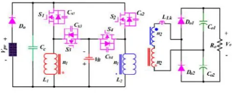
[image:3.595.309.556.173.278.2]The three port dc to dc converter is used for charging and discharging the battery it act as buck boost converter. The converter can provide a high step-up capability for power conversion systems including the PV array, the battery storage, and the isolated load consumption (Yazdani and Dash, 2009). The primary side of the proposed converter is equivalent to a bidirectional Buck–Boost converter, while the secondary side is a Buck converter in DCM. The output voltage can be controlled by PS on the primary side bridge arm, which can be approximated to adjust the duty cycle of Buck converter of secondary side to realize output voltage regulation. In addition to galvanic isolation, the three-port triple-active-bridge(TAB) converter topology has the advantage of easily matching different port voltage levels in the overall system. This can be done just by choosing the appropriate numbers of turns for the windings. This circuit allows a fixed frequency operation and utilization of the leakage inductance of the transformer as the energy transfer element. Each bridge generates a high-frequency voltage (square-wave in the simplest case) with a controlled phase shift angle with respect to the primary side (Yazdani and Iravani, 2010). The voltages presented to the windings have the same frequency. power flow between the three ports can be controlled by the phase shifts. The maximum possible power flow is determined by the leakage (and externally added) inductances. This circuit can be operated with soft-switching, provided that the operating voltage at each port is kept near constant. However, when the port operating voltage varies widely, such as with super capacitors, the soft-switched operating range will be reduced. A method has been proposed to extend the soft-switching range by adjusting the duty ratio of the voltage (a rectangular-pulse wave) inversely proportional to the operating voltage of the port.
Fig.4. Three port DC-DC converter
The proposed converter topology is illustrated in the above Figure (Yazdani and Iravani, 2010). The main switches S1 and S2 transfer the energy from the PV to the battery or load, and can work in either interleaved or synchronous mode. The
switches S3 and S4 are operated in the interleaved mode to transfer energy from source to load. L1 and L2 are two coupled inductors whose primary winding (n1) is employed as a filter and the secondary windings (n2) are connected in series to achieve a high-output voltage gain. LLK is the leakage inductance of the two coupled inductors and N is the turns ratio from n2 /n1. CS1, CS2, CS3, and CS4 are the parasitic capacitors of the main switches S1, S2, S3 and S4, respectively.
Fig.5. Diagram of the proposed control scheme
The maximum power point tracking (MPPT) (Konstantopoulos and Koutroulis, 2014) can be implemented by adjusting the duty cycle of switching devices. In the MPPT loop, the PV voltage is regulated to follow an optimal operating point, which is initially assigned to 80% of the open-circuit voltage of the PV array (Konstantopoulos and Koutroulis, 2014)). This point can be determined by the outer MPP Tracker. Moreover, the PV voltage regulation loop is used to improve the MPPT performance. In the output voltage control loop shown in Fig.8 the phase angle of the modulation carrier is the control variable, which regulates the output voltage to follow the expected voltage.
III. Modeling of PV panel with its basic equation
A. PV Panel Design
MXS 60 PV Module is taken as the reference module for simulation and the data sheet details are given in Table I In addition to that, series resistance (Rs) of PV module is taken as
0.2Ω, band gap energy (Eg) of the semiconductor used is taken
as 1.1 eV and ideality factor(A)of semiconductor is taken as1.6.Maintaining the Integrity of the Specifications (Bragard
[image:3.595.45.283.575.675.2]et al., 2010)
Table I. Key specification of MSX 60 PV module
PV module Parameter Variable Value
Maximum power Pm 60W
Maximum voltage Vm 17.1 V Current at max power Im 3.5 A Open circuit voltage Voc 21.06 V Short circuit current Isc 3.74 A Total No. of cells in Series Ns 36 Total No. of cells in Parallel Np 1
B. Equivalent Circuit of PV module
[image:3.595.313.555.620.705.2]with a single-diode as shown in fig. Rs and Rsh are the series and shunt resistance of solar cell and they are usually neglected to simplify the analysis as the value of Rsh is very large and that of Rs is very small.
Fig.6. Equivalent circuit of Solar Cell
Usually the output power of a solar cell is very less and of no practical use unless it is increased by some means. So in order to increase the output power of solar PV systems, the solar cells are connected in series and parallel configurations to form solar PV modules and arrays.
C. Light Generated Photocurrent
The module photocurrent depends linearly on the solar irradiation level and is also influenced by the temperature according to the following equation
(1) Where, Isc is the cell short-circuit current at a 25 °C and 1 kW/m2; Ki is the cell short-circuit current temperature coefficient; T is cell working temperature; Tr is the cell
reference temperature and λ s the solar irradiance level in
[image:4.595.42.277.110.188.2]kW/m2
Fig.7. Simulink model of photocurrent
D. Model of Temperature Conversion
The temperature used in the mathematical equations of solar PV module is in Kelvin units, Figure 3 is to convert the operating temperature from degree Celsius units to Kelvin units using the following equation.
[image:4.595.346.524.295.374.2](2) Where, T(K)is temperature in Kelvin and T(ºC) is temperature in degree Celsius.
Fig.7. Simulink model of the temperature conversion from degree Celsius unit to Kelvin unit
IV. Proposed topology to integrate solar PV and battery storage system for five level inverter
A. Existing Topology to Integrate Solar PV and Battery Storage system Using an Five-Level Inverter for induction motor application
Fig.8. Block diagram for five level inverter
The solar panel output is given to the dc to dc converter and then the battery is integrated and then the inverter is connected to the induction motor. The output of the panel is given to the dc to dc converter and the if the output of the panel is high then it is given to the battery as well as the inverter if the panel output is low then the battery will supply the inverter. The battery will also charge when the panel output is high. The solar panel used here is msx 60 pv panel, the converter used is three port dc to dc converter and the battery used is nickel metal hydride and the inverter is the Five level neutral point clamped inverter(NPC)and then it is connected to the induction motor and the variable speed control of induction motor is also achieved.
A. Structure of a Five Level Inverter
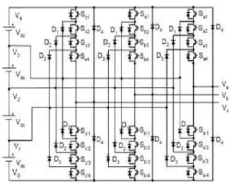
A three phase five level diode clamped inverter is shown in Figure 9. Each of the three phases of the inverter shares a common dc bus, which has been subdivided by four capacitors into six levels. The voltage across each capacitor is Vdc, and the voltage stress across each switching device is limited to Vdc through the clamping diodes. Table III lists the output voltage levels possible for one phase of the inverter with the negative dc rail voltage V0 as a reference. State condition 1 means the switch is on, and 0 means the switch is off. Each phase has five complementary switch pairs such that turning on one of the switches of the pair require that the other complementary switch be turned off (Park et al., 2003). The complementary switch pairs for phase leg a are (Sa1, Sa‘1), (Sa2,Sa‘2), (Sa3, Sa‘3) and (Sa4, Sa‘4). Table also shows that in a diode -clamped inverter, the switches that are on for a particular phase leg is always adjacent and in series.
[
Isc
Ki
(
T
Tr
)]
Iph
273
)
(
T
c
T(k)
with a single-diode as shown in fig. Rs and Rsh are the series and shunt resistance of solar cell and they are usually neglected to simplify the analysis as the value of Rsh is very large and that of Rs is very small.
Fig.6. Equivalent circuit of Solar Cell
Usually the output power of a solar cell is very less and of no practical use unless it is increased by some means. So in order to increase the output power of solar PV systems, the solar cells are connected in series and parallel configurations to form solar PV modules and arrays.
C. Light Generated Photocurrent
The module photocurrent depends linearly on the solar irradiation level and is also influenced by the temperature according to the following equation
(1) Where, Isc is the cell short-circuit current at a 25 °C and 1 kW/m2; Ki is the cell short-circuit current temperature coefficient; T is cell working temperature; Tr is the cell
reference temperature and λ s the solar irradiance level in
[image:4.595.38.289.468.583.2]kW/m2
Fig.7. Simulink model of photocurrent
D. Model of Temperature Conversion
The temperature used in the mathematical equations of solar PV module is in Kelvin units, Figure 3 is to convert the operating temperature from degree Celsius units to Kelvin units using the following equation.
(2) Where, T(K)is temperature in Kelvin and T(ºC) is temperature in degree Celsius.
Fig.7. Simulink model of the temperature conversion from degree Celsius unit to Kelvin unit
IV. Proposed topology to integrate solar PV and battery storage system for five level inverter
A. Existing Topology to Integrate Solar PV and Battery Storage system Using an Five-Level Inverter for induction motor application
Fig.8. Block diagram for five level inverter
The solar panel output is given to the dc to dc converter and then the battery is integrated and then the inverter is connected to the induction motor. The output of the panel is given to the dc to dc converter and the if the output of the panel is high then it is given to the battery as well as the inverter if the panel output is low then the battery will supply the inverter. The battery will also charge when the panel output is high. The solar panel used here is msx 60 pv panel, the converter used is three port dc to dc converter and the battery used is nickel metal hydride and the inverter is the Five level neutral point clamped inverter(NPC)and then it is connected to the induction motor and the variable speed control of induction motor is also achieved.
A. Structure of a Five Level Inverter
A three phase five level diode clamped inverter is shown in Figure 9. Each of the three phases of the inverter shares a common dc bus, which has been subdivided by four capacitors into six levels. The voltage across each capacitor is Vdc, and the voltage stress across each switching device is limited to Vdc through the clamping diodes. Table III lists the output voltage levels possible for one phase of the inverter with the negative dc rail voltage V0 as a reference. State condition 1 means the switch is on, and 0 means the switch is off. Each phase has five complementary switch pairs such that turning on one of the switches of the pair require that the other complementary switch be turned off (Park et al., 2003). The complementary switch pairs for phase leg a are (Sa1, Sa‘1), (Sa2,Sa‘2), (Sa3, Sa‘3) and (Sa4, Sa‘4). Table also shows that in a diode -clamped inverter, the switches that are on for a particular phase leg is always adjacent and in series.
with a single-diode as shown in fig. Rs and Rsh are the series and shunt resistance of solar cell and they are usually neglected to simplify the analysis as the value of Rsh is very large and that of Rs is very small.
Fig.6. Equivalent circuit of Solar Cell
Usually the output power of a solar cell is very less and of no practical use unless it is increased by some means. So in order to increase the output power of solar PV systems, the solar cells are connected in series and parallel configurations to form solar PV modules and arrays.
C. Light Generated Photocurrent
The module photocurrent depends linearly on the solar irradiation level and is also influenced by the temperature according to the following equation
(1) Where, Isc is the cell short-circuit current at a 25 °C and 1 kW/m2; Ki is the cell short-circuit current temperature coefficient; T is cell working temperature; Tr is the cell
reference temperature and λ s the solar irradiance level in
kW/m2
Fig.7. Simulink model of photocurrent
D. Model of Temperature Conversion
The temperature used in the mathematical equations of solar PV module is in Kelvin units, Figure 3 is to convert the operating temperature from degree Celsius units to Kelvin units using the following equation.
(2) Where, T(K)is temperature in Kelvin and T(ºC) is temperature in degree Celsius.
Fig.7. Simulink model of the temperature conversion from degree Celsius unit to Kelvin unit
IV. Proposed topology to integrate solar PV and battery storage system for five level inverter
A. Existing Topology to Integrate Solar PV and Battery Storage system Using an Five-Level Inverter for induction motor application
Fig.8. Block diagram for five level inverter
The solar panel output is given to the dc to dc converter and then the battery is integrated and then the inverter is connected to the induction motor. The output of the panel is given to the dc to dc converter and the if the output of the panel is high then it is given to the battery as well as the inverter if the panel output is low then the battery will supply the inverter. The battery will also charge when the panel output is high. The solar panel used here is msx 60 pv panel, the converter used is three port dc to dc converter and the battery used is nickel metal hydride and the inverter is the Five level neutral point clamped inverter(NPC)and then it is connected to the induction motor and the variable speed control of induction motor is also achieved.
A. Structure of a Five Level Inverter
Fig.9. Three phase five level structure of a NPC inverter
Table II. Switching states of Five level inverter
Fig.10. Output Voltage of Battery
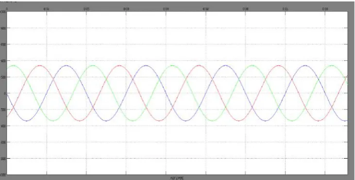
Fig.11. Output waveform of five level harmonics
[image:6.595.71.519.696.786.2]Fig.12. Output waveform of three level harmonics
Table III. Simulated Output voltage
S.No Components Practical value for three level Practical value for five level
1. Pv panel 24v 24v
2. Converter 576.5 v 522.4v
4. Inverter 230v 230v
The advantages of NPC inverter are:
(i) All of the phases share a common dc bus, which minimizes the capacitance requirements of the inverter. For this reason, a back-to-back topology is not only possible but also practical for uses such as a high-voltage back-to-back inter-connection or an adjustable speed drive.
(ii) The capacitors can be precharged as a group.
(iii) Efficiency is high for fundamental frequency switching
V. Simulation and validation of the proposed topology and control system
Simulations have been carried out using MATLAB/Simulink to verify the effectiveness of the proposed topology and control system.
The solar pv and battery integration using npc inverter the pv panel is msx 60 pv the output of pv 24v and is given to the converter the converter is three port dc to dc converter this converter act in buck mode as well as in boost mode and with that battery is connected. The converter switching operation are done by the mppt the technique used in mppt is frequency division method. The output of the converter is given to the inverter that generates the ac waveform with the ouput voltage 230v.
V. Conclusion and future work
In exixting system multilevel inverter is used in that there are some disadvantage the control is much more complex and the techniques are still not widely used in industry. This disadvantages are reduced by Five level NPC inverter. A five level voltage source inverter that can integrate with both renewable energy and battery storage on the dc side of the inverter. A extended unbalance three-level vector modulation technique that can generate the correct ac voltage under unbalanced dc voltage conditions has been proposed. A new control algorithm for the proposed system has also been presented in order to control power flow between solar PV, battery, and grid system, while MPPT operation for the solar PV is achieved simultaneously. The proposed topology and control algorithm was tested using MATLAB and results are presented. In the results the proposed system is able to control ac-side current, and battery charging and discharging currents at different levels of solar irradiation. The five level NPC inverter that can reduce the harmonics in the ac voltage and it is connected to the induction motor and speed contro is also achieved.
REFERENCES
Basu K. and N. Mohan, “A high-frequency link single-stage PWM inverter with common-mode voltage suppression and source-based commutation of leakage energy,”IEEE Trans.
Power Electron., vol. 28, no. 8, pp. 3907–3918, Oct. 2014. Bragard M., N.Soltau, S.Thomas, et al. "The Balance of
Renewable Sources and User Demands in Grids:Power Electronics for Modular Battery Energy Storage Systems," IEEE Transactions on Power Electronics, vol. 25, pp. 3049-3056,2010.
Hamid R. Teymour, Danny Sutanto, Kashem M.Muttaqi, P.ciufo," Solar pv and battery storage integration using three level inverter," IEE Trans. on energy conversion, vol. 29, no. 2 Jun 2014.
Hu, Y., Y. Deng, Q. Liu, and X. He, “Asymmetry three-level grid-connected current hysteresis control with varying bus voltage and virtual over-sample method,” IEEE Trans. Power Electron., vol. 29, no. 6, pp. 3214–3222, Jun. 2014 Konstantopoulos C. and E. Koutroulis, “Global maximum
power point tracking of flexible photovoltaic modules,” IEEE Trans. Power Electron., vol. 29, no. 6, pp. 2817–
2828, Oct. 2014
Li W., W. Li, X. Xiang, Y. Hu, and X. He, “High step-up interleaved converter with built-in transformer voltage
multiplier cells for sustainable energy applications,” IEEE Trans. Power Electron., vol. 29, no. 6, pp. 2829–2836, Jun. 2014
ParkS. J., F. S. Kang, M. H. Lee, and C. U. Kim, ―A new
single -phase five-level PWM inverter employing a deadbeat control scheme,‖ IEEE Trans. Power Electron.,
vol. 18, no. 18,pp. 831–843, May 2003
Pou J., J. Zaragoza, S. Ceballos, M. Saeedifard, and D.
Boroyevich, “A carrier-based PWM strategy with zero-sequence voltage injection for a three-level neutral-point-clamped converter,”IEEE Trans. Power Electron.,vol. 27,
no. 2, pp. 642–651, Feb. 2012.
Rodriguez J., S. Bernet, P. K. Steimer, and I. E. Lizama, “A
survey on neutral-point-clamped inverters,” IEEE Trans. Ind. Electron., vol. 57,no. 7, pp. 2219–2230, Jul. 2010. Selvaraj J. and N. A. Rahim, "Multilevel Inverter For Grid
Connected PV System Employing Digital PI Controller," IEEE Trans. Ind.Electron., vol. 56, pp. 149-158, 2009. Toledo M., D. Oliveira Filho, and A. S. A. C. Diniz,
"Distributed photovoltaic generation and energy storage systems: A review," Renewable and Sustainable Energy
Reviews, vol. 14, pp. 506-511, 2010.
VillalvaM. G., J. R. Gazoli, and E. R. Filho, “Comprehensive
approach to modeling and simulation of photovoltaic
arrays,” IEEE Trans. Power Electron., vol. 24, no. 5, pp.
1198–1208, May 2009.
Wei-dong J., D. Shao-wu, C. Liu-chen, Y. Zhang, and Q.
Zhao, “Hybrid PWM strategy of SVPWM and VSVPWM
for NPC three-level voltagesource inverter,” IEEE Trans.
Power Electron., vol. 25, no. 10, pp. 2607–2619, Oct. 2010. Xinchun L., Shan Gao, J. Li, H. Lei, and Y. Kang, “A new
control strategy to balance neutral-point voltage in
three-level NPC inverter,” in Proc. IEEE 8th Int.Conf. Power Electron. ECCEAsia, May/Jun. 2011, pp. 2593–2597. Yazdani A. and P.Dash, "A Control Methodology and
Characterization of Dynamics for a Photovoltaic (PV) System Interfaced With a Distribution Network," IEEE Transactions on Power Delivery, vol. 24, pp. 1538-1551,
2009
Yazdani A. and R. Iravani, Voltage-Sourced Converters in
Power Systems. New York, NY, USA: Wiley, 2010.
Yazdani A., A.R. DiFazio, H.Ghoddami, et al. "Modeling Guidelines and a Benchmark for Power System Simulation Studies of Three-Phase Single-Stage Photovoltaic Systems," IEEE Transactions on Power Delivery, vol. 26, pp. 1247-1264, 2011.