A
NUMERCIAL STUDY OF
SINGLE-PHASE FORCED CONVECTIVE HEAT
TRANSFER IN MICROCHANNELS
WITH RECTANGULAR
CROSS SECTIONS
P. MOHAJERI KHAMENEH*
Department of Mechanical Engineering, Faculty of Engineering, Urmia University, Urmia, 57169-33111, Iran
I. MIRZAIE, N. POURMAHMOUD, M.RAHIMI EOSBOEE, S. MAJIDYFAR Department of Mechanical Engineering, Faculty of Engineering, Urmia University,
Urmia, 57169-33111, Iran M. MANSOOR
Department of Mechanical Engineering, Faculty of Engineering, Ferdowsi University of Mashhad, Mashhad, 91775-1111, Iran
Abstract:
Three dimensional simulations in microchannel heat exchangers with rectangular cross sections are investigated numerically in this study. In these simulations forced convective heat transfer and laminar flow of single-phase water are considered. In order to measure heat transfer parameters in these rectangular microchannels, FLUENT CFD Solver is used in this numerical method. For the purpose of creating geometry and exert boundary and initial conditions in the present model, finite volume method in Computational Fluid Dynamics is used in this study. In the present study, at each Z-location, variation of local temperatures, heat flux and Nusselt number at the whole tube is investigated in detail. Thereafter, averaged computational Nusselt number in this model is calculated. In addition, conceivable pressure drops have been obtained at each Z-location in this model. Then, pressure drop values in the present model are explored. Finally, all the numerical results for this kind of microchannel will be discussed precisely.
Keywords: Heat exchanger; Numerical simulation; Laminar flow; Rectangular port; Microchannel.
1. Introduction
Microchannel structures are utilized widely for more than 20 years in miscellaneous industries. These systems are used by manufacturers who wanted efficient heat exchange in a compact design. Today, the advantages of microchannel systems are beginning to challenge traditional coil technology in different
*
manufactures. As an example, the air conditioning industry faces a continuous challenge to provide higher efficiency levels and greater equipment reliability. This challenge is even more difficult to meet when the aim is simultaneously to maintain equipment size and reduce potential cost influence.Previous engineering solutions designed to compensate these requirements have typically included such changes as improving individual components or increasing the overall heat transfer surface area to increase thermal efficiency. However, each of these improvements tends to increase equipment size, cost, or both. An optional solution for air conditioning applications is microchannel heat exchanger technology. This heat exchanger technology has been widely used in the automotive industry for many years, with considerable success [1].
The importance of convective heat transfer in microchannel structures has increased dramatically because of practical applications involving the thermal control of electronic devices. In the earliest investigation of microscale flow and heat transfer, Tuckermann and Pease [2] studied the fluid flow and heat transfer characteristics in microchannels, and demonstrated that electronic chips could be effectively cooled by means of the forced convective flow of water through microchannels fabricated either directly in the silicon wafer or in the circuit board on which the chips were mounted. Since this initial study other investigations have supported the earliest findings and have served to illustrate the unusually high levels of heat removal that can be accomplished using microchannel structures [3].
Shortly after the initial work of Tuckermann et al. [2,3], Wu and Little [4,5]measured the flow friction and heat transfer characteristics of gases flowing through microchannels and observed that the convective heat transfer characteristics departed from the typical experimental results for conventionally sized channels. Other investigations by Choi et al. [6], Weisberg et al. [7] and Bowers and Mudawar [8] all provided additional information and considerable evidence that the behavior of fluid flow and heat transfer in microchannels or microtubes is substantially different from that which typically occurs in larger channels or tubes. In an attempt to clarify some of the questions surrounding this issue, Peng and Wang [9] and Peng et al. [10] investigated microchannel structures. In these investigations the heat transfer and flow mode conversions for single phase forced convection in microchannels were studied. Peng and Peterson [11] analyzed experimentally the effects of thermofluid and the geometric variables on the heat transfer using methanol flowing through microchannel structures. Peng et al. [12,13] measured both the flow friction and the heat transfer for single-phase convection in an array of parallel microchannels.
A numerical study about three-dimensional fluid flow and heat transfer in a rectangular microchannel heat sink was analyzed numerically using water as the cooling fluid by Qu and Mudawar [13]. One of their major goal was to present a detailed description of the local and average heat transfer characteristics, i.e. temperature, heat flux, and Nusselt number in microchannel heat sinks. From their investigation it was found that the highest temperature is encountered at the heated base surface of the heat sink immediately above the channel outlet and also it was stated that the heat flux and Nusselt number have much higher values near the channel inlet and vary around the channel periphery, approaching zero in the corners.
Therefore, a comprehensive review was presented on the investigations of the forced single-phase convective heat transfer in non-circular microchannels by Peng et al. [14]. In their literature the observations and results available in the open literature are inspected and compared for better understanding of the physical nature of the heat transfer performance. From their investigations it is concluded that appropriate data reduction and the correlating parameters will be the basis of comparability and evaluation for comprehensive investigations.
Consequently, the heat transfer characteristics of single-phase forced convection of R134a through single circular micro-channels with 1.7, 1.2, and 0.8 mm as inner diameters were investigated experimentally by Owhaib and Palm [15]. The results were compared both to correlations for the heat transfer in macroscale channels and to correlations suggested for microscale geometries. The results show good agreement between the classical correlations and the experimentally measured data in the turbulent region. In the laminar regime, the heat transfer coefficients were almost identical for all three diameters.
In this article, heat transfer characteristics in microchannels with rectangular cross section are investigated numerically. In this study, variation of temperature, heat flux and Nusselt number in these kind of microchannels are examined in detail. In these present simulations, single-phase water in laminar flow is considered as “working fluid” in these investigations. FLUENT CFD Solver is selected as an appropriate software in order to calculate heat transfer parameters in this paper. Then, pressure drop values in the present model were explored. Finally, after observation the trend of temperature, heat flux and Nusselt number for single-phase water in this kind of microchannel results will be discussed precisely.
2. Description of Numerical Simulation Procedure
In the present paper, FLUENT CFD Solver is used to investigate heat transfer parameters in microchannels with rectangular cross section and then obtained results will be investigated in detail. After several exact simulations, required results will be obtained in this model. In fact, the major aim of this study is to investigate heat transfer characteristics in this kind of microchannels. In this numerical method, in order to have higher exactness in calculations, three dimensional computations and analysis is used.
In this article, in order to reach to maximum capacity of heat transfer, efficient options in FLUENT CFD Solver are selected that they will result maximum temperature difference between hot and cold water. For the purpose of reasonable results, initial and boundary conditions are selected close to experimental conditions as much as possible. Finally, it is attempted that the detailed and reasonable explanations are demonstrated for each results.
3. Assumptions of Physical Models
In the present model microchannel geometry and existing boundary and initial conditions based on actual conditions which they are exerted in laboratories are defined. Whereas, in this model the length of the tube is longer than the length of hydrodynamic entrance zone. So, the flow of this fluid is assumed “developed” in further simulations. Other assumptions which they are considered in these simulations are listed below:
1. In order to describe fluid flow and heat transfer in this physical model, three dimensional Navier-Stokes and energy equations were utilized.
2. The process is steady and the fluid is incompressible. 3. The flow is laminar.
4. The body forces are neglected.
5. Radiation heat transfer and natural convective heat transfer are neglected. 6. Aluminum is used for jacket (outer tube) in this present model.
4. Governing Equations and Boundary Conditions
According to the above assumptions, the Navier-Stokes and energy equations are utilized to describe the fluid flow and heat transfer in the whole region of this model. The governing equations are:
Continuity:
.(
fV
)
0
(2)Momentum:
)
.(
)
.(
fV
V
P
f
V
(3)Energy:
)
.(
))
(
.(
V
fc
p,fT
k
f
T
Where kf ,
f,
f,
c
p,f represent the thermal conductivity of water, molecular viscosity, density and specificheat at constant pressure of water flow, respectively.
5. Computational Modelling and Boundary Conditions
After review of previous studies in this research area, it is concluded that in channel surfaces in comparison to outer tube finer meshing should be used. In these simulations in order to decrease the volume of calculations and the number of iterations in FLUENT CFD Solver a section of model is used for these simulations. With using of “SYMMETRY” options for number of walls in this simulation- instead of full simulation- a section of this model could be simulated with the same accuracy. In figure 1, the geometry of this rectangular port with its geometric characteristics is shown. Meanwhile, in this figure, Z-direction and X-Y plane are the indicators for the direction of fluid flow and cross section plane, respectively.
Fig. 1. rectangular port geometries in microchannel heat exchanger
In figure 2, a general view of cross section for this rectangular microchannel is shown.
Fig. 2. Cross section of microchannel with rectangular ports
In the meanwhile, after several investigations among available and reputable experimental results, in table 1 geometric characteristics of this microchannel with rectangular ports are tabulated.
Parameter Length (mm)
Wport 0.47
Hport/2 0.33
tport/2 0.11
ttube 0.32
Hjacket 12.25
Ltube 1000
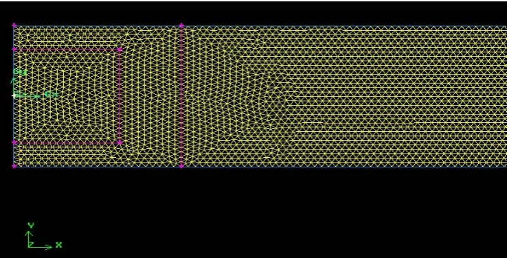
Besides, after examination and comparison those several kind of meshing finally “Tri-Pave” meshing is selected in Gambit Software. This kind of meshing has high accuracy and it can save the iteration time extremely. In figure 3, this kind of selected meshing is presented.
Fig. 3. Partial geometry and grid generated of microchannel with rectangular ports
Moreover, in order to gain confidence that all these numerical results aren’t affiliated to different grid dimensions after exertion of meshing process, a grid independence examination is performed in this three dimensional model. In this study, based on number of grids which are available during the meshing procedure, three kind of grid qualities (fine, mediocre and harsh) were generated. After comparing iteration results and convergence speed, between these three kind of grids “mediocre meshing” is selected as a base model in order to continue further investigations and iterations in this numerical simulation.
6. Numerical Solution
By using reputable and available experimental results from previous articles, initial and boundary conditions are defined exactly for this present model. At first, in order to determining the water mass flow rate (
m
), equation 5 is exerted.port h
ReA
m
D
(5)In order to locate Dhin equation 5, the value of hydraulic diameter is calculated with using of equation 6, as
follows:
perimeter
Wetted
area
tion
cross
D
h
4
(
sec
)
(6)The Darcy–Weisbach formulation, Equation 7, which it is presented in “Introduction to Heat Transfer” [17], will be utilized to determine pressure drop in laminar region of fluid flow. By placing Darcy friction factor (f) in equation (7), pressure outlets are calculated for each simulation.
2
.
.
hL
V
p
f
D
2
(7)Above procedure for calculating pressure drops present admissible results. Consequently, initial and boundary conditions, pressure drop and friction factor (f) which they were applied in simulation of this rectangular microchannel are tabulated in table 2.
Table 2. Initial conditions of microchannel with rectangular ports
Parameter Tube Jacket
Tin (K) 283.6 333
) /
(kg s
m 2.7E-05 0.02
Re 25.3 1205.7
f 3.36 0.04
Pgauge (Pa) 5430.6 2.97
Finally after the process of modelling and meshing, grid dependency process and also exact assigning of initial and boundary conditions, iteration process will be started.
7. Results and Discussion
7.1. Wall and Fluid Local Temperature
One of the most important aims in this simulation is to calculate wall and fluid temperature at each Z-location in the depth of this model. In this three dimensional numerical simulation with utilizing “X-Y plot” option in Fluent CFD Solver, the trend of variations for wall and fluid temperature are calculated. Finally, after averaging the results in Microsoft Excel at each Z location, temperature profiles for wall and water fluid are acquired. Wall and water fluid temperatures at each Z- locations are shown in Figure 4.
Fig. 4. Local fluid and wall temperature of microchannel with rectangular ports
As it can be seen in figure 4, with moving in the +Z direction, a decreasing temperature difference is obtained. As it is cleared, the maximum temperature difference will be occurred in the cold water inlet region or in the other words it will be happened in the outlet zone of the hot water.
As it is shown in figure 4 and with moving in the +Z direction, fluid and wall temperature could not reach together in any sections of this model.
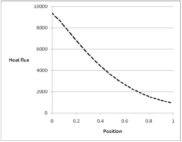
7.2. Local heat flux variation
Fig. 5. Local heat flux variation for microchannel with rectangular ports
As it is cleared in figure 5, the maximum rate of heat flux is occurred in hot water outlet region. Based on temperature diagram in figure 4, it is obvious that maximum heat flux will be happened in that indicated region. With moving in +Z direction, the rate of heat flux is decreased gradually. Finally, in hot water inlet region because of minimum temperature difference between fluid and wall temperature, the minimum rate of heat flux is occurred.
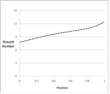
7.3. Local Nusselt number variation
The main goal of this section is to calculate local Nusselt number at each Z location along the tube length of this microchannel. With utilizing parameters which they were calculated later such as; wall and fluid temperatures, heat flux,...and with using equation (8), local Nusselt number can be obtained at each Z location.
f h f
w k
D z T z T
z q z
Nu
) ( ) (
) ( '' )
( (8)
Which kf, Dh and q’’ are indicated thermal conductivity of water, hydraulic diameter of ports and heat flux,
Fig. 6. Local Nusselt number distribution for microchannels with rectangular ports
With moving in +Z direction the local Nusselt number will be increased gradually because two efficient parameters in Nusselt number formula i.e.: heat flux and wall and fluid temperatures have a similar trend in this model. Finally, as it is cleared in figure 6, maximum local Nusselt number is occurred in the inlet region of hot water because in this region thermal boundary layer is beginning to develop.
7.4. Computational average Nusselt number
In order to calculate the averaged Nusselt number in outer tube of this rectangular microchannel, obtained values for local Nusselt number which they were listed in Microsoft Excel should be averaged. In this solution the distance for each grid is assumed 0.03. Consequently, averaged Nusselt number in the outer tube of this present model is presented, as:
87
.
9
,Numerical
avgNu
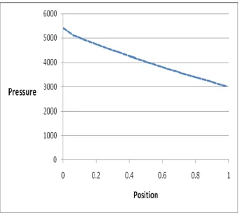
7. Microchannel pressure drop
Fig. 7. Variation in pressure values along the Z direction in microchannel with rectangular ports
Since a sudden flow contraction and expansion existed at the entrance and exit of the microchannels, the actual measured pressure drop included these contraction and expansion losses. The pressure drop, in figure 7, however, represents the pressure drop only along the microchannels, hence, the calculated pressure drop caused by the contraction and expansion were subtracted from the measured values.
8. Conclusions
References
Keogh, A. (2007): Microchannel heat exchangers, IEA Heat Pump Centre, 25(3), 15-17.
[1] Tuckermann, D.B.; Pease, R.F. (1982): Optimized convective cooling using micromachined structure, J. Electrochem. Soc. 129(3), C98.
Tuckerman, D.B. and Pease, R.F. (1991), “High-performance heat sinking for VLSI”, IEEE Electron device Letters, Vol. EDL-2, pp.126-129.
Wu, P.Y. and Little, W.A. (1983), “Measurement of friction factor for the flow of gases in very fine channels used for micro miniature Joule-Thompson refrigerators”, Cryogenics, Vol. 23, No. 5, 273-277.
Wu, P.Y., and Little, W.A. (1984), “Measurement of the heat transfer characteristics of gas flow in fine channels heat exchangers used for micro miniature refrigerators”, Cryogenics, Vol. 24, No. 8, 415-420.
Choi, S.B., Barron, R.F. and Warrington, R.O. (1991), “Liquid flow and heat transfer in microtubes, In Micromechanical Sensors, actuators and systems”, Dynamic systems and control division, Vol. 32, 123-134.
Weisberg, A., Bau, H.H. and Zemel, J. (1992), “Analysis of microchannels for integrated cooling”,
International Journal of Heat and Mass Transfer, Vol. 35, No. 10, 2465-2474.
Bowers, M.B. and Mudawar, I. (1994), “High flux boiling in low flow rate, low pressure drop minichannel and microchannel heat sinks”, International Journal of Heat and Mass Transfer, Vol. 37, No. 2, 321-332.
Peng, X.F., and Wang, B.X. (1993), “Experimental investigation on flow boiling of liquid through microchannels”, Chinese Journal of Engineering Thermophys, Vol. 14, No. 3, 281-286.
Peng, X.F., Wang, B.X., Peterson, G.P. and Ma, H.B. (1995), “Experimental investigation of heat transfer in flat plates with rectangular microchannels”, International Journal of Heat and Mass Transfer, Vol. 38, No. 1,
127-137.
Peng, X.F. and Peterson, G.P. (1995), “The effect of thermofluid and geometrical parameters on convection of liquids trough rectangular microchannels”, International Journal of Heat and Mass Transfer, Vol. 38, No. 4,
755-758.
Peng, X.F. and Peterson, G.P. (1995), “Frictional flow characteristics of water flowing through rectangular microchannels”, Journal of Experimental Heat and mass transfer, Vol. 7, No. 4, 249-264.
Peng, X.F., Peterson, G.P. and Wang, B.X. (1995), “Heat transfer characteristics of water flowing through microchannels”, Journal of Experimental Heat and mass Transfer, Vol. 7, No. 4, 265-283. Qu, W. and Mudawar, I. (2002), “Analysis of three-dimensional heat transfer in microchannel heat sinks”,
International Journal of Heat and Mass Transfer, Vol. 45, No. 19, 3973-3985.
Peng, X.F., Piao, Y. and Jia, L. (2002), “Single-phase convective heat transfer in microchannels”, Progress in Natural Science, Vol. 12, No. 10, 721-728.
Owhaib,W. and Palm, B. (2004), “Experimental investigation of single-phase convective heat transfer in circular microchannels”, Experimental Thermal and Fluid Science, Vol. 28, No. 2-3, 105-110.
Mokrani, O., Bourouga, B., Castelain, C. and Peerhossaini, H. (2009), “Fluid flow and convective heat transfer in flat microchannels”, International Journal of Heat and Mass Transfer, Vol. 52, No. 5-6, 1337-1352. Incropera, F.P., DeWitt, D.P., Bergman, T.L. and Lavine, A.S. (2007), Introduction to Heat Transfer, Fifth