O R I G I N A L
Open Access
Development of a pellet boiler with Stirling
engine for m-CHP domestic application
Luigi Crema
*, Fabrizio Alberti, Alberto Bertaso and Alessandro Bozzoli
Abstract
A new sustainable technology has been designed by Fondazione Bruno Kessler through its unit Renewable Energies and Environmental Technologies. This technology is realized integrating in a single system (1) a Stirling engine (mRT-1K) from a pre-engineering design of Allan J. Organ; (2) a micro-heat exchanger technology, to reduce the net transfer unit deficit on the hot side of the heat engine; (3) a customized pellet boiler, able to extract electrical and thermal power; and (4) a customized hydraulic circuit, connecting the cool side of the Stirling engine and the heat generation on the second section of the pellet boiler. The objective of this paper was to present a new technology for the micro-cogeneration of energy at a distributed level able to be integrated in domestic dwellings. Most part of the available biomass is used in buildings for the generation of thermal power for indoor heating and, in minor cases, for hot sanitary water. In the Province of Trento, 88% of the biomass is used for this purpose. The full system is actually under integration for the test phase and not yet tested. The first tests on the single components have confirmed preliminary results on the Stirling engine with respect to the tolerances, pressurization, and proper integration of the electrical generator-driven control system. The pellet boiler has been tested separately, confirming an overall thermal efficiency of 90%.
Keywords:micro-cogeneration, Stirling engine, pellet boiler, renewable energy
Background
The cogeneration of energy at a distributed level is one of the leading arguments in large part of energy policies related to renewable energy resources and systems. The actual marketable solar systems for domestic and dis-tributed applications (photovoltaic [PV] and solar ther-mal) suffer notable limitations: (1) The low overall (electrical) efficiency of PV systems creates a small col-lected energy from the available space, sometimes restricted in the surface to a few square meters; (2) the stagnation temperatures on solar thermal collectors are actually limiting the diffusion of solar thermal systems; and (3) fixed and non-retrofittable systems may generate energy in an intermittent manner not aligned with the auto-consumption profile of domestic spaces.
On the other end, the growth of the distributed energy generation is far above all previsions, not only in new energy markets but even in highly industrialized coun-tries. In Germany, more than 50% of the 43-GW
installed power in 2009 is in the hands of individuals and farmers, on all sectors of solar, wind, biomass tech-nologies [1]. At the distributed level, an increasing num-ber of technologies are approaching the market, such as new and efficient PV or concentrated photovoltaics [2]; micro-combined heat and power [m-CHP] solutions based on solar [3], fuel cells [4], or biomass; and tech-nologies for the efficient production of thermal energy such as ground source heat pumps, air heat pumps, and solar thermal.
The development of new cogeneration systems based on non-intermittent sources able to be coupled and eventually hybridized with other sustainable technologies is highly required. A compact micro-cogeneration sys-tem based on a pellet boiler integrated with a Stirling engine is presented, realized compatibly with the mar-ket-levelized energy cost. This paper presents, for the first time, the different stages of the development of such m-CHP biomass technology.
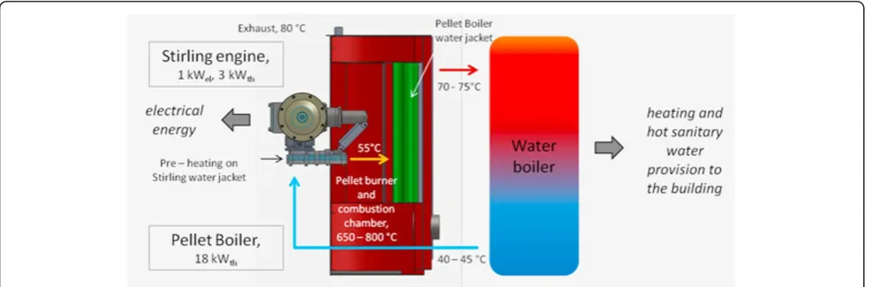
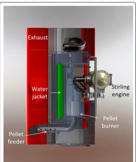
Such system (see Figure 1) integrates a Stirling engine (mRT-1k) in a customized pellet boiler properly realized to generate thermal power for heating and eventual * Correspondence: [email protected]
Renewable Energies and Environmental Technologies Unit (REET), Fondazione Bruno Kessler (FBK), Via alla Cascata 56/C, Povo Trento, Italy
cooling, electricity, and hot sanitary water. Four main themes have led to the development of this proposal:
- Improvements in combustion technology allow the adaptation of a retrofitted combustion chamber with the Stirling heat exchanger in a new efficient solu-tion, optimizing the electricity generasolu-tion, the heat removal from different parts of the system at differ-ent temperatures, and the overall efficiency.
- Optimized Stirling engines and new compact heat exchanger technology can reduce the costs and improve the performance of small heat engines, so they can operate with higher proportions of Carnot efficiency on the working temperatures (~600°C) from the combustion burner.
- The high cost and low power efficiency of gas-fuelled m-CHP systems, combined with increases in natural gas prices, both absolute and relative to elec-tricity prices, can undermine the financial viability of gas-fuelled m-CHP. There is an urgent need for alternative m-CHP systems, of which solar or bio-mass m-CHP, whether separately or as a hybrid, is an option with high potential.
The system may work in two different operative modes:
1. Generating the electrical power only when ther-mal energy is required by the building
2. Generating the electrical power dissipating the extra thermal energy not required by the building
The first will be used in most parts of the applications where a grid connection is available, and the second will regard remote locations (mountain cottages) where the grid connection is not present. An electrical energy sto-rage will be required to match energy generation with
end-user demand of energy. In both cases, the pellet boiler will be provided with a volumetric control of the pellet in order to make the burner work at a low power (>5 kWth).
Materials and methods
Introduction to economical aspects
The biomass combustion systems (biomass boilers and stoves) are one of the most diffused and cost-effective heating systems in the Alpine region. The overall effi-ciency obtained by the best and state-of-the-art technol-ogies is comparable to those on natural gas or fossil fuel boilers, with values above 80%. The m-CHP generation from a pellet or wood burner is a potential added value to the base technology.
A market analysis reveals that Italy is the first Eur-opean country in the specific market sector of the pellet stoves, accounting for 800,000 domestic systems installed at 2008 and 380,000 units produced in 2006. It adds a growth of 300% in the last 5 years (2003-2008) in pellet consumption and use. To have a comparison data, in Europe, there have been 4.4 Mt produced in 2006 with respect to 8.4 Mt in 2010 [5]. In the European energy market, biomass has a share of 51% with respect to the energy produced by renewable sources, of which 85% comes from domestic plants and about 15% from industrial plants (multistage combustion, gasification, pyrolysis processes). In addition, the direct production of thermal energy from renewable sources, about 97%, comes from biomass combustion [6]. In addition, 97% of all direct thermal energy from renewable sources comes from biomass combustion.
A recent report from Frost and Sullivan [7] showed that biomass can provide a strong support to renewable energies in the European context. This source provides currently two thirds of the specific sector and has a strong growing margin since the raw material produced
Figure 1Technological layout for the micro-cogeneration pellet boiler. Cremaet al.Energy, Sustainability and Society2011,1:5
http://www.energsustainsoc.com/content/1/1/5
in the EU 25 territory is increasing. The same report underlines the biomass context, which is wrongly con-sidered an energy resource of the past, that financing support for technological development can provide solu-tions for an advanced system, reduction of costs (the conversion ratio€/kW is one of the more advantageous
in the market, with costs lower than 2,000 €/kWe),
environmental sustainability, and lower levels of impact. The present project aims to realize a system which is capable of covering a part of the demand for electrical energy and the demand for thermal energy for heating and hot sanitary water purposes.
Following are some considerations on domestic system for cogeneration:
-There is a good match between production and demand of electrical energy since a pellet stove is mainly used during the part of the day which also has an electrical demand. For this reason, most of the electrical energy is consumed locally.
-Modularity of the generation system: The system can support different demands of electrical and ther-mal power. The electrical conversion ratio and the thermal output can be regulated by changing the load in the combustion chamber.
-The external combustion engine provides a silent, clean, and reliable system with limited cost for man-agement and maintenance.
-With an averaged electrical efficiency from a full load to a partial load of about 10%, the electrical
potential production is 3 TWhe/year for the
8,400,000 tons of pellets produced yearly in Europe. Since the wood production is at least one order of magnitude higher, the whole potential electrical pro-duction is 35 TWh/year, which is roughly one tenth of the electrical production in EU from nuclear plant.
The pellet boiler m-CHP system
The pellet cogeneration boiler is based on the integra-tion between a Stirling engine and a biomass pellet boi-ler. The subcomponents of the specific technology are under integration. They include a Stirling engine, the mRT-1k, pre-engineered by Allan J. Organ [8].
The overall system is designed as illustrated in Figure 1. The Stirling engine is integrated directly inside the combustion chamber. Its heat exchanger is immediately above the burner. The Stirling engine can start operat-ing and generatoperat-ing electrical and thermal power after a transient time to keep the engine at proper working conditions (hot and cold temperatures, energy flow through the heat exchanger). A drive control electronic
system activates the Stirling engine controlling the gen-erator and making it working as a motor.
A spiral screw, electronically controlled, advances the pellet. The burner is designed to provide stoichiometric primary air to realize a flame of 18 kWth. The pellet
boi-ler is mainly composed of (1) a burning chamber con-nected to primary air which is blown inside using a forced flow system; (2) an internal water circuit to remove thermal power after the Stirling engine and maintain the exhaust temperature in the range of 80°C; and (3) an external water boiler to store thermal energy for the heating of the indoor environment and the pro-duction of hot sanitary water. The hydraulic system comes from the boiler; the water is pumped inside the cold end of the Stirling engine to cool and maintain a temperature of about 45-50°C. It goes to the boiler heat remover and goes back to the water boiler at a tempera-ture of about 75°C. The mass flow of the pellet and the water will be calibrated as a function of the energy bal-ance able to maintain the system in a steady-state ther-mal condition. The electrical power is derived by the engine adapting to the specific condition of the grid connection and acting through a load management system.
Measurement system
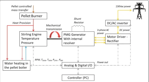
The integrated technology will be provided with a cen-tralized measurement and control system (see Figure 2). It will be directly connected to the different sub-components. The controller monitors temperatures in and out from the boiler water jacket, inside the Stirling engine, in the expander cylinder, in the compression cylinder, at the input and at the output of the water circuit, at the exhaust of the boiler, the volume flow on the water circuit passing though the Stirling, and inside the pellet boiler. Furthermore, the pressure sen-sors, both for dynamic and absolute values, are posi-tioned inside the Stirling engine on the heat exchanger and before the compression cylinder; the pellet mass flow sensor is located at the input of the burner. In such a way, the energy and mass balance will be monitored.
Results
The cogeneration engine
The mRT-1k engine is a 1-kW air-charged (14-bar gauge) reciprocating Stirling engine. It is expected to be upgradeable (up to 5 kW and more) by (1) using higher pressure He as the charge gas, (2) increasing engine speed, and/or (3) scaling up in size. The initial engine, illustrated in Figure 3, is a two-cylinder, 90° engine. The model of the engine gives back a rated power output of 1 kWpickat 1,500 rpm. It is characterized by a compact
design withnominal displacement,Vmax- Vminof 175
cm3 (VE = 72 cm3, VC = 162 cm3; thermodynamic
volume ratio,= 2.25).
It has a Beale modulus, an index for the efficiency and effectiveness of the engine, Bn, given in Equation 1,
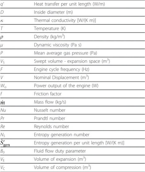
which make use of symbols explained in Table 1.
Bn= Wo
PVF = 0.148. (1)
This is a modest value surpassed in some established designs. But it should be possible to exceed that value, thereby improving on the target 1-kW rating.
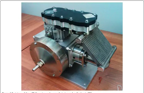
In Figures 3 and 4, the pre-engineering design and the advanced manufacturing stage of the engine are pre-sented. Different critical components of the cogenera-tion technology have been modeled and optimized with respect to the heat transfer, fluid dynamics, and the overall efficiency extractable from the system.
Particularly, the mRT-1k has been optimized in the main components of the Stirling engine, which include:
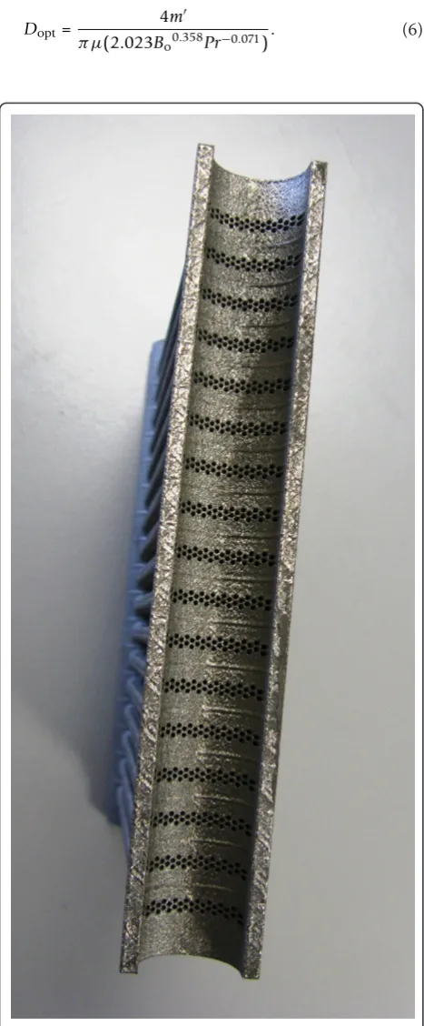
1.Regenerator of the engine: a new technology with improved performance (under patenting process) 2.Heat exchanger: the application of the micro-heat exchanger fluid dynamics and realized through a selective laser melting [SLM] process (see Figure 5 for a pre-design of the heat exchanger)
The integration in the pellet boiler technology must respect some constraints, such as:
-Design able to realize a condition of clear surface with limited powder deposition problems
-Design able to provide an easy maintenance of the system
-High external surface exposed to the flame radiosity -High internal surface for efficient heat transfer to the pressurized internal gas of the Stirling
The above constraints had been taken to a proposed solution of a heat exchanger based on micro-fluid dynamics, which improve the energy density transferred through the exchanger while maintaining a lower Rey-nolds number and, subsequently, a limited pressure drop with respect to the convective heat transfer coefficient.
The heat exchanger design has been based on the entropy generation minimization for the internal flow of
Figure 2Measurement and control system for the m-CHP technology. Cremaet al.Energy, Sustainability and Society2011,1:5
http://www.energsustainsoc.com/content/1/1/5
the heat exchanger, where the working fluid of the engine is located. Minimizing the entropy generations in one component is equivalent to minimizing the loss of available work. The objectives were to increase the wall
fluid heat transfer without causing a damaging increase in the pumping power demanded by the forced-convec-tion arrangement. The method combines from the start the most basic principles of thermodynamics, heat trans-fer, and fluid mechanics [9,10].
For the heat exchanger, the entropy generation is described by Equation 2. Symbols used for the following set of equations are explained in Table 1.
˙ Sgen=
q2 πκT2Nu+
32m3f
π2ρ2TD5. (2)
The Nusselt number is a result taken from the field of heat transfer (Equation 3):
Nu= 0.023ReD0.8Pr0.4. (3)
The friction factor is a result taken from fluid mechanics (Equation 4):
f = 0.046ReD−0.2. (4)
The entropy generation minimization is related to the optimal value for the pressure drop through a thermo-dynamic system and the maximization of the heat trans-fer, as reported in Equation 5:
NS= ˙
Sgen ˙
Sgen,min = 0.856
ReD
ReD,opt
−0.8
+ 0.144
ReD
ReD,opt
4.8
. (5)
The first term on the right-hand side is the contri-bution made by the heat transfer, while the second term is the contribution due to fluid friction. The
Figure 3Pre-engineering of the mRT-1k engine.
Table 1 List of symbols
q’ Heat transfer per unit length (W/m)
D Inside diameter (m)
Thermal conductivity [W/(K m)] T Temperature (K)
r Density (kg/m3) μ Dynamic viscosity (Pa s) P Mean average gas pressure (Pa)
VS Swept volume - expansion space (m3)
F Engine cycle frequency (Hz)
V Nominal Displacement (m3)
Wo Power output of the engine (W)
f Friction factor
˙
m Mass flow (kg/s) Nu Nusselt number
Pr Prandtl number
Re Reynolds number
NS Entropy generation number
˙
Sgen Entropy generation per unit length [W/(K m)] B0 Fluid flow duty parameter
VE Volume of expansion (m3)
VC Volume of compression (m 3
Figure 4Prototype of the mRT-1k engine under manufacturing and realization in FBK.
Figure 5Model of the micro-heat exchanger realized for the Stirling engine. Cremaet al.Energy, Sustainability and Society2011,1:5
http://www.energsustainsoc.com/content/1/1/5
following equation (Equation 6) can be derived for the optimal duct dimensioning of the internal flow. The optimal diameter is averaged over one complete cycle of the Stirling engine and is found in an itera-tive way.
Dopt= 4m
πμ(2.023Bo0.358Pr−0.071). (6)
For the proposed technology, an optimal diameter of 1.03 mm has been obtained for the internal forced flow. The modeled solution is based on a design which comprises 612 parallel fluid ducts of 1 mm in internal diameter and 600°C on the hot heat exchanger side. By using the same approach, the method could be extended to the external flow of the combustion products in order to obtain the whole optimization for the heat exchanger. The micro-heat exchanger has been realized through a SLM process from the micro-powder of AISI 316L stainless steel. The proto-type is shown in Figures 6 and 7. The spatial resolution of the process can reach a value around 0.2 mm.
The pellet boiler
The pellet boiler will be manufactured starting from an initial prototype to realize a final market technology. Figure 8 shows the first design for the boiler, which will have a dedicated burner (Figure 9) placed below the Stirling heat exchanger.
The pellet is inserted by an automatic spiral screw which can be controlled with respect to the heat input by changing its velocity. The primary air is injected at the burner level and controls part of the combustion process, the flame temperature, and power; it is able to provide the correct amount of combustive agent. Depending on process thermal requirements, the power can be ranged from 18 to 5 kWth, which is the
minimum power required by the Stirling engine to
generate 1 kWe at the output. While the peak power
will be used to take the system at the working condi-tions, the steady state will be maintained through the minimum power to keep the engine running and gen-erating electrical energy at a rated power output. In such way, the system will be cogenerating energy for a
larger amount of hours per year, increasing the eco-nomic benefits from the system. At the present time, it has not been possible to develop a full calorific value boiler due to potential corrosion effects at the exhaust of the system caused by particulate, sulfur, and other contaminants potentially at a dangerous concentration inside the biomass pellet.
The electrical generator and the load management system
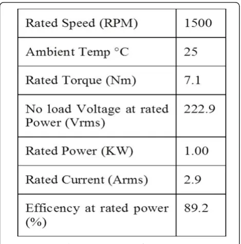
The mRT-1k Stirling, to generate electrical power, is interfaced with an electrical generator and a control drive. The electric generator is a three-phase perma-nent magnet generator, customized by Moog Italiana, able to generate 1 kWel at a speed rate of 1,500 rpm
(see Figure 10).
The generated electrical power is controlled by moni-toring the thermal energy generated by the pellet burner and transferred inside the Stirling engine. The drive control (see Figure 11) will brake the engine at an opti-mal speed at the maximum overall efficiency, coupling the rotational speed of the engine with the electrical power generated. At the same time, the generated
Figure 8Pellet boiler rendering.
Figure 9Pellet boiler burner.
Figure 10Moog’s electrical generator. Cremaet al.Energy, Sustainability and Society2011,1:5
http://www.energsustainsoc.com/content/1/1/5
power requires stabilization to a fixed voltage level before the second stage of conversion to AC voltage. This must be pursued according the standards set by the energy management agency (i.e., 50 Hz of frequency value at a voltage of 230 ACV and the admitted level of DC current components).
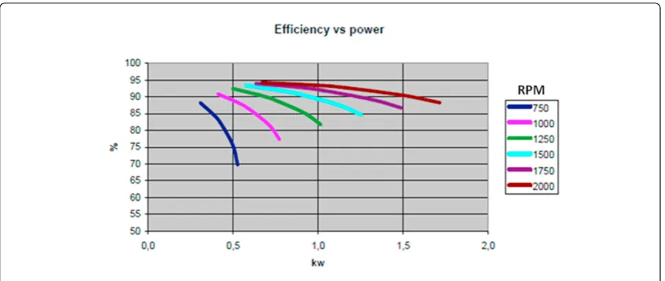
To perform the above described steps, a series of components has been selected, respectively a control drive provided by Moog Italiana (see properties in Fig-ures 12, 13 and 14) and an inverter for wind power applications, suitable for a wide range of testing conditions.
The efficiency of these two electrical conversions are respectively 88-90% for the first stage between mechani-cal power and direct voltage and 90-95% for the second stage through the inverter, in the range of 1 kWe. The
efficiency can increase significantly at rising power over 2-3 kWe. In a few months, the two conversions can be
performed by a two-axis control drive under realization by Moog industries; this new drive control will integrate in a single unit the two previous mentioned systems and will be able to reach an overall efficiency of 92-95%, integrating a sensorless generator control.
Conclusions
The presented technology is entering the testing process in laboratory-controlled conditions at a first stage of the mRT-1k tests and inside the boiler prototype in a sec-ond stage. The test bench has been realized in Fsec-onda- Fonda-zione Bruno Kessler [FBK] for both stages based on:
-Natural gas burner-controlled mass balance, through a mass flow controller applied to the gas duct, and energy balance, through the calculus of the energy content on the different stages, from the input gas mass flow to inside the engine and in the water external cooling circuit -On the pellet boiler, mass and energy balance at the different stages, inside the burner, in the Stirling engine and in the water circuit
Figure 11Moog’s drive control.
The technology will be tested with respect to perfor-mance and overall efficiency, noise level and reliability, long-term tests, and mean time before fault index. The full system will then be included in a series of planned projects inside the Province of Trento, such as the
‘Tomorrow’s Mountain Cottages,’a territorial program
launched by the Province of Trento, and the ‘FBK
-MIT Sustainable Connected Home’, a project in coop-eration between Fondazione Bruno Kessler and the Massachusetts Institute of Technology. A start-up activity has been planned for the industrialization and commercialization of the final technology. The impact at the local level can either be supported by the local
Energy Agency of the Province of Trento to small-scale biomass conversion plants and installations with respect to bigger cogeneration biomass power plants. A lot of the local activities are on the way to realize a whole chain of stakeholders involved at the local level [11].
Acknowledgements
The authors would like to extend some acknowledgements mainly to the Editor, to Dagmar Fiedler, to Michael Narodoslawsky, and all colleagues at TU Graz and eseia [European Sustainable Energy Innovation Alliance]. Special thanks also to the Autonomous Province of Trento and to the Energy Agency of the Province of Trento for supporting the demonstration of the technology in theBioDomUsproject.
Authors’contributions
LC carried out main developments and scientific coordination on the technology design and realization. FA participated and performed all thermodynamic analysis and modelling. AB worked out the part on the mechanical design for the integration of the Stirling in the pellet boiler and has performed the development of the variable speed control system. ABo participated in the general definition of the technology and on the overall management, giving support to coordination. All authors read and approved the final manuscript.
Competing interests
The authors declare that they have no competing interests.
Received: 8 September 2011 Accepted: 21 November 2011 Published: 21 November 2011
References
1. Farrell J Distributed energy generation = big numbers.http://www.grist.org/ people/John±Farrell
2. Camisada D (2010) Building integrated concentrating photovoltaic: a review. Renew Sustain Energ Rev 15(1):603–611
3. DiGeSPo project Distributed generation from a small size concentrated solar power.http://www.digespo.eu/
4. Briguglio N, Ferraro M, Brunaccini G, Antonucci V (2011) Evaluation of a low temperature fuel cell system for residential CHP. Int J Hydr Energ 36(13):8023–8029
5. Palazzetti M Proposals to boost biomass for heat market in Europe.http:// www.aebiom.org/IMG/pdf/Palazetti.pdf
Figure 13Generator Output power vs. Speed.
Figure 14Main electric generator performances. Cremaet al.Energy, Sustainability and Society2011,1:5 http://www.energsustainsoc.com/content/1/1/5
6. Douard F Boosting bioenergy in Europe. Expobioenergia‘06: Topics in Biomass Domestic Heating. First International Bioenergy Congress, Valladolid, October 2006
7. Strategic Assessment for European Biomass Energy Markets. Frost & Sullivan. http://www.frost.com/prod/servlet/report-toc.pag?repid=M249-01-00-00-00 8. Organ AJ mRT-1k engine.http://web.me.com/allan.j.o/
Communicable_Insight/Welcome.html
9. Bejan A (1996) Entropy generation minimization: the new thermodynamics of finite-size devices and finite-time processes. J Appl Phys 79(3):1191–1218 10. Durmayaz A, Sogut S, Sahin B, Yavuz H (2004) Optimization of thermal
systems based on finite-time thermodynamics and thermoeconomics. Prog Energ Combust Sci 30:175–217
11. Giuliani F, Baldo M, Grisenti B La filiera foresta - legno - energia.http://www. legnotrentino.it/documenti/Pubblicazioni/2011/Maggio/
Report_Biomassa_def.pdf
doi:10.1186/2192-0567-1-5
Cite this article as:Cremaet al.:Development of a pellet boiler with Stirling engine for m-CHP domestic application.Energy, Sustainability and Society20111:5.
Submit your manuscript to a
journal and benefi t from:
7Convenient online submission 7Rigorous peer review
7Immediate publication on acceptance 7Open access: articles freely available online 7High visibility within the fi eld
7Retaining the copyright to your article