IJIRT 147614
INTERNATIONAL JO URNAL OF INNOVATIVE RESEARCH IN TECHNOLOGY251
Heat Transfer Augmentation of Shell and Tube Heat
Exchanger by Providing FIN Using CFD
Prof. Arvind Singh
1, Bhoopendra Patel
2 1Corporate Institute of Science and Technology, Professor, RGPV Bhopal, MP, INDIA
2Corporate Institute of Science and Technology, Research Scholar, RGPV Bhopal, MP, INDIA
Abstract- The conversion, utilization, and recovery of energy in industrial, commercial, and domestic application usually involve a heat transfer process. Improved heat exchange, over and above that in the usual or standard practice, can significantly improve the thermal efficiency in such applications as well as the economics of their design and operation.
The need to increase the thermal performance of heat transfer equipment (for instance, heat exchangers), thereby effecting energy, material, and cost savings as well as a consequential mitigation of environmental degradation has led to the development and use of many heat transfer enhancement techniques. These methods are referred to as augmentation or intensification techniques. A multi pass shell and tube heat exchanger with 3 tubes with fins modelling is done using ANS YS 14.5 and meshing has done using ICEM CFD software, simulations has done by using CFD-FLUENT software. Using Fluent, computational fluid dynamics software the pressure drop, Temperature variations and heat transfer are analysed under turbulent flow condition. Nanofluid such as Al2O3-H2O is used as cooling medium. The CFD simulated results achieved from the use of the creating fin in tube side in shell and tube type heat exchanger are compared with without fin. Based on the results, providing fins on tube causes the increment of surface area and Overall heat transfer coefficient which results in the enhancement of heat transfer rate of heat exchanger.
Index Terms- S hell and tube heat exchanger, CFD, Overall heat transfer coefficient, Heat transfer.
I. INTRODUCTION
Heat transfer is a science that studies the energy transfer between two bodies due to temperature difference. When material’s temperature increases, the thermal agitation of its constituent molecules will increase. Then the areas which contain greater molecular kinetic energy will pass this energy to areas with less kinetic energy.
So when an object or fluid is at different temperatu re than its surroundings, the heat transfer will occur in such a way that the body and the surroundings reach thermal equilibrium.
A heat exchanger is a device which used to transfer thermal energy (enthalpy) between two or more fluids, between a solid surface and a fluid, or between solid particulates and a fluid, at different temperatures and in thermal contact.
Generally, there are three types of heat transfer which are conduction, convection and radiation.
Conduction is the transfer of heat within an object or between two objects in contact.
Convection heat transfer occurs when a fluid (liquid or gas) comes in contact with a material of a different temperature.
1. For natural convection, it occurs when the flow of a fluid is primarily due to density differences within the fluid due to cooling or heating of that fluid.
2. Meanwhile, forced convection occurs when the flow of fluid is primarily due to pressure differences.
Radiation is the transfer of heat from one object to another by means of electro-magnetic waves. Radiation does not require objects to be in contact or fluid flow between those objects, it occurs in the void of space (that’s how the sun warms us). Transfer of thermal energy can also occur with any combination of the three. In our study which relates to plate heat exchanger, it consists of heat transfer by conduction and convection.
IJIRT 147614
INTERNATIONAL JO URNAL OF INNOVATIVE RESEARCH IN TECHNOLOGY252
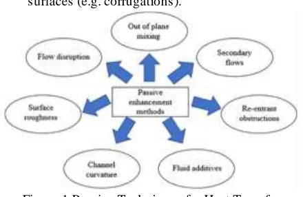
Surface can be enhanced basically by two types: Active enhancement which requires deployment of external power which is obviously higher in operational and capital cost thus commercially unviable.
Passive enhancement which adding extended surfaces (e.g. fins), or employing interrupted surfaces (e.g. corrugations).
Figure 1 Passive Techniques for Heat Transfer Augmentation
Shell and tube Heat Exchangers
Shell and tube Heat Exchangers are one of the most popular types of exchanger due to the flexibility the designer has to allow for a wide range of pressure and temperature.
A Shell and tube heat exchanger is a class of heat exchanger designs. It is the most common type of heat exchanger in oil refineries and other large chemical process, and is suited for higher
There are two main categories of Shell and Tube Heat Exchanger, one is those which are used in petrochemical industries and the other is those which are used in power industries such as feed water heaters and power plant condensers.
Nano fluids
Nano fluid, a suspension of nanoparticles in a continuous and saturated liquid, has been found capable to get considerably higher thermal conductivities than their respective base fluids resulting in better convective heat transfer coefficients.
Fluids have higher specific heat compare to metals, and metals have higher thermal conductivity compare to solids. So when we added a small amount of nanoparticle to base fluid it will increase the thermal conductivity of base fluid.
II. LITERATURE REVIEW
Year / Authors Journals Topic Outcomes
K Somasekhar (2017)
Science Direct
A CFD investigation of heat transfer enhancement in shell and tube heat exchanger using Al2O3
-H2O Nanofluids.
• For effecting cooling of shell and tube heat exchanger Al2O3-H2O Nanofluids is the better
cooling medium than the Distilled water cooling medium.
• By using of different % Al2O3-H2O Nanofluids as a
cooling medium heat transfer increases on tube side than the Distilled water cooling medium.
V.Velmurugan (2017)
IJM ET Heat Transfer enhancement in
Shell and tube heat exchanger using inserts
• The twisted tape inserts performed better than pebbles and glass sphere packing.
• The effect of usage of twisted tape inserts, glass sphere packing and pebbles in enhancing the overall heat transfer rate has been studied. 4
Seid M ahdi
Jafari (2017)
JAFARI Designing and application of a shell
and tube heat exchanger for
Nanofluids thermal processing of liquid food products
Application of Nanofluids through shell and tube heat exchangers might be carried out successfully with substantial reduction in processing time and energy,
Davood Panahi (2016)
Science Direct
Heat transfer enhancement of shell-and-coiled tube heat exchanger utilizing helical wire turbulators.
Generally, this type of turbulators can be used for helical tubes and the result is higher heat transfer rate and obviously extra pressure drop.
III.METHODOLOGY
This section describes the CFD tools required for carrying out a simulation and the process one follows
in order to solve a problem using CFD. The hardware required and the three main elements of processing CFD simulations: the pre‐processor, processor, and post‐processor are described.
IJIRT 147614
INTERNATIONAL JO URNAL OF INNOVATIVE RESEARCH IN TECHNOLOGY253
1. Pre‐processor- A pre‐processor is used to definethe geometry for the computational domain of interest and generate the mesh of control volumes (for calculations). General, the finer the mesh in the areas of large changes, the more accurate the solution. Fineness of the grid also determines the computer hardware and calculation time needed. The open‐source pre‐ processor used for this project is called Salomé. 2. Solver- The solver makes the calculations using
a numerical solution technique, which can use finite difference, finite element, or spectral methods. Most CFD codes use finite volumes, which is a special finite difference method. 3. Post‐Processor- The post‐processor provides for
visualization of the results, and includes the capability to display the geometry/mesh, create vector, contour, and 2D and 3D surface plots. Particles can be tracked throughout a simulation, and the model can be manipulated (i.e. changed by scaling, rotating, etc.), and all in full color animated graphics. Para View is the open‐source post‐processor used for this project.
Table 1 Specifications of Shell and Tube SPECIFICATIONS OF
SHELL
SPECIFICATIONS OF THE TUBES
M aterial Stainless steel
M aterial Stainless
steel inner
diameter
208 mm Inner
diameter
14 mm
Outer diameter
218 mm Outer
diameter
16 mm
Length 500 mm Length 1000 mm
No. of tube 3
The model of shell and tube type heat exchanger are modeled in design modular.
Fig. 2 Geometry model of shell and tube Heat Exchanger
MESHING
The designed model of Heat Exchanger is meshed in ICEM Meshing.
The meshing type have done is quardcore and tetrahedral.
Numbers of nodes -473198.
Numbers of elements that are used are 2097041.
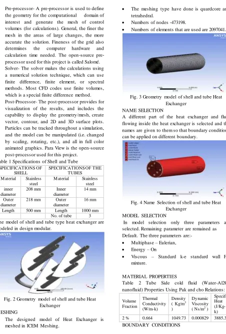
Fig. 3 Geometry model of shell and tube Heat Exchanger
NAME SELECTION
A different part of the heat exchanger and fluid flowing inside the heat exchanger is selected and the names are given to them so that boundary conditions can be applied on different boundary.
Fig. 4 Name Selection of shell and tube Heat Exchanger
MODEL SELECTION
In model selection only three parameters are selected. Remaining parameter are remained as Default. The three parameters are:-
Multiphase – Eulerian,
Energy – On
Viscous – Standard k-e standard wall Fn, mixture.
MATERIAL PROPERTIES
Table 2 Tube Side cold fluid (Water-Al2O3 nanofluid) Properties Using Pak and cho Relations:
Volume Fraction
Thermal Conductivity (W/m-k)
Density ( Kg/m3
)
Dynamic Viscosity ( Ns/m2 )
Specific Heat (J/Kg-k)
2 % 0.664 1049.73 0.000829 3885.36
IJIRT 147614
INTERNATIONAL JO URNAL OF INNOVATIVE RESEARCH IN TECHNOLOGY254
Here in the analysis the boundary condition is sameas considered by scholar’s K.Somashekhar et.al. (2017) during the previous work. Some of the conditions are shown The boundary conditions that are applied on the model are as below:
Table 3 Bounadry conditions
Specification Fluid Inlet
Temp M ass Flow rate
Cold fluid Water-Al2O3 303 K 0.09 kg/s
Hot fluid Water 363 K 0.61 kg/s
IV. RESULTS AND DISCUSSIONS
Heat transfer through heat exchanger depends on the mass flow rate and temperature of fluid flowing inside the heat exchanger. In current flow rate of 0.09 Kg/s of cold fluid and 0.61 Kg/s of hot fluid have been considered. Fins are provided on the tube is kept triangular to maximize the area of heat transfer. To analyze the cumulative effect of nanofluid and fins on the heat exchanger rate, the CFD model of heat exchanger has been developed. The main purpose of the present work is obtaining the maximum value of overall heat transfer rate. That can be calculated by using formula written below:
Q = U A 𝝷m × No of tubes
Where,
Q = Heat transfer in watts A = Surface Area in square meter
𝝷m = LMTD in kelvin
Fig.5 Contours of Static Temperature
Fig.6 Contours of Static temperature on U- tube
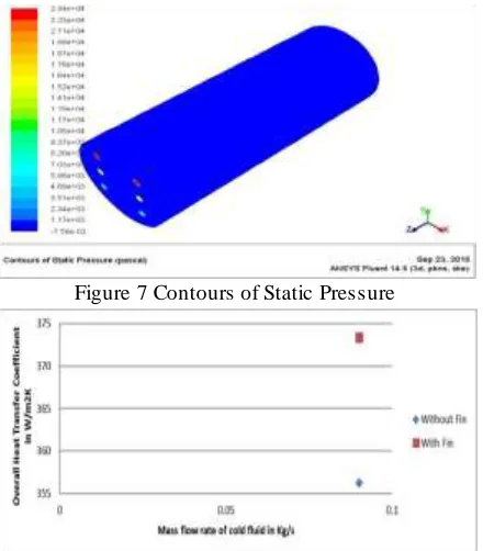
Figure 7 Contours of Static Pressure
Figure 8: mass flow rate of cold fluid V/S overall heat transfer coefficient.
V. CONCLUSIONS
In this analysis, the cumulative effect on fins and nanofluid in shell and tube heat exchanger has been investigated using CFD analysis. Based on the results obtained by the CFD and mathematical calculations it is found that:
From the CFD analysis it has been observed that at mass flow rate of cold fluid i.e. 0.09Kg/s and hot fluid i.e. 0.68 Kg/s, the overall heat transfer coefficient increased by 4.77% by using fins and nanofluid.
From the CFD analysis it has been observed that at mass flow rate of cold fluid i.e. 0.09Kg/s and hot fluid i.e. 0.68 Kg/s, the outlet temperature of cold fluid increased by 14 Kelvin by using fins and nanofluid.
Figures shows that overall heat transfer comparison for overall heat transfer coefficient, which confirms that net heat transfer is maximum when fins and nanofluid is used together.
REFERENCES
IJIRT 147614
INTERNATIONAL JO URNAL OF INNOVATIVE RESEARCH IN TECHNOLOGY255
[2] J.Koo, C.Kleinstrecer, Laminar Nano fluid flowin micro heat sink. International journal of heat and mass transfer 48(2005).
[3] Shung-Wei Kang, Wei-Chiang Wei, Sheng-Hong Tsai, Shih-Yu YANG, Experimental investigation of silver Nano fluid on heat pipe thermal performance, Applied thermal engineering 26(2006).
[4] Shuichi Torii, Experimental study on convective heat transfer of aqueous suspension of Nano diamond particle, International symposium on Eco Topia science 07 (2007).
[5] S.J.Kim, I.C. Bang, J.Buongiorno,and, and L.N.Hu, Study of pool boiling and critical heat flux enhancement in Nano fluid.bullletin of the polish academy of sciences technical science.vol55,no 2,2007.
[6] PaisarnNaphon, Pichai Assad among Kol, TeerapongBorirak, Experimental investigation of titanium Nano fluid on the heat pipe thermal efficiency, International communication in HMT 35 (2008).
[7] S.H.Anil Kumar and G.Jilani, convective heat transfer enhancement in an enclosure with fin utilizing Nano fluid, International journal of aerospace and mechanical engineering.
[8] Yu-Tang Chen, Experimental study of silver Nano fluid on heat pipe thermal performance, Journal of marine science and technology, vol18, No.5 pp.731-734.
[9] Eed Abdel-Hafer ABDEL-Hadi, Sherif Handy Taher, Abdel Hamid Mohamed Torki, and Samar sabryHauad, Heat transfer analysis of vapour compression system using Nano Cuo-R134a International conference on advanced materials engineering vol. 15(2011).
[10]WeerapunBuangthongsuk and Somchai Wongwises, Heat transfer enhancement and flow characteristic of alumina- water Nano fluid flowing through a micro channel heat sink. The second TSME International conference on mechanical engineering. 19-21 October 2011. [11]Yanuar, N.Putra, Gunawan S.M.Bagi, Flow and