Software and Hardware Integration Oriented to an
Intelligent Lighting System: Study case- Colombian
Development
Alejandra Rojas Arias, Manuel Alfredo Figueredo Medina
Abstract-- This paper1 presents a project developed in Colomb ia in order to contribute to national industry through the creation of an Intelligent Lightning System. To achieve this, it was necessary to include topics about Product Development and Software Engineering. The whole system must be integrated to offer it as a unique system made in Colombia.
Index Term-- DALI protocol, Lightning System, Wireless Module, Remote Web Software, SOA, Remote Wireless Control.
1. INTRODUCTION
The current energy problem has become evident. From Industrial Revolution, most of the Human Being activities involved power consumption, and a large amount of this energy comes from nonrenewable sources, generating a huge socia l and environmenta l impact. Recently, there have been increasing efforts to create alternatives trying to reduce the damage generated by the growing demand of electricity, some of these related to efficient generation processes, the tendency to use renewable energy sources and promotion about optimizing energy usage.
This paper comes up with a description about the development of an inte lligent lighting system that optimizes energy usage; reduce related costs to energy consumption by enhanc ing daylight use; and inc ludes a wireless module that get easier and cheaper the installation process . This development has taken place in response to various needs that have been found in Colombia, listed below [1]:
Most of the solutions offered in Colombia are oversized for the real needs of Colombian Market. This fact has led to expensive solutions, making them non-feasible for small-scale applications.
This work was supported in part by “Concliencias” Administrative Department of Science, Technology and Innovation and CIDEI (Research and
Technological Development of the Electronics and Computer Industry). Alejandra Rojas Arias, M.Sc. in Project Management. B.Sc. in Electronic Engineering, Hardware Development Director at CIDEI, Bogotá, Colombia
Manuel Alfredo Figueredo Medina. M.Sc. in System Engineering. B.Sc. in Chemical Engineering. Software Director at CIDEI, Bogotá, Colombia
The electric and electronic industry in Colombia cannot compete with foreign suppliers, due to its lack of development and knowledge about handling cutting-edge technology. It has resulted in a Colombian market full of foreign suppliers.
In Colombia, most of the implemented solutions are in big buildings, due of the cost of the actual suppliers.
A research was made about related systems offered in Colombian market. Results show that all systems have many common characteristics [2]:
Management Software Create and schedule scenes. Individual control for each lamp
It can handles a wide lamp types (halogen, incandescent, LED)
Allows the user to perform manual control through switches.
Control by scene, by time, by light intensity, On/Off and by schedules.
Inclusion of wireless sensors
It generates energy consumption reports grouped per day, per week, per month, per ye ar, a. o.
These features were included into the developed Smart Lighting System. But, in order to be competitive in local and globa l market, some additional features were added. Some of these features are:
Remote Management Web Software
Graphical Navigation through the software environments
It is a scalable system as it can handle from a small space to a large amount of buildings, simply by adding control units.
It can handles a wide DALI devices from different manufacturers
Customizable graphical environment
Inclusion of smart wireless devices that can work as a simple low cost system
Low cost system
Below is presented a detailed description of each of the components described in Figure 1
Fig. 1. General System Architecture. [Own Elaboration]
2. SYSTEM DESCRIPTION
Figure 1, shows the general architecture proposed for the system. It has web enabled software that manages all components of the system. It will have a further description later. It is named "Light Management System" or LMS.
The LMS communicates with the control unit, which mainly cons ists of a Programmable Fie ld bus Controller (PFC). The next level is a wireless devices network which can be used as a master/slave system (depending on PFC instructions) or in autonomous mode. These characteristics offer an easy insta llation at a low cost, providing a high va lue to the product. This system also includes a wireless remote control that allows the user to manage and setup the system. The last layer contains the peripheral devices, which executes instructions given by previous layers; these are DALI devices, which are available in the market.
3. COMMUNICATION PROTOCOLS
For the conditions given by the system architecture, it was necessary to implement different communication protocols to transmit and receive data from components. Figure 2 presents the protocols used at each layer:
Fig. 2. Implemented Communication Protocols [Own Elaboration]
ETHERNET/IP: It is an Industria l protocol structured by Open DeviceNet Vendors Association (ODVA). [3]
EtherNet/IP was used in the LMS implementation for connecting it with the PFC that manages field devices (lighting drivers). Every PFC controls its own devices and send EtherNet/IP messages to the LMS to manage the whole system [4].
DALI: Digita l Addressable Lighting Interface is a dedicated protocol solely for lighting control. This means that DALI cannot be used to control other systems such as BMS. However, DALI is effective for scene selection and for getting feedback regarding faulty light sources. This makes it very useful to use together with Building Automation Systems where remote supervision and service reports are required [5] [6].
In this particular case, DALI has been implemented on the PFC, and it has been fully replicated on a wireless module. The use of DALI ensures the ability for the system to be compatible with a variety of peripherals from various manufacturers, allowing the user to select the device that best suits his budget or needs [7].
ZIGBEE®: It allows establishing networks and interconnecting wire less devices easily. Additiona lly ZigBee® can be implemented on low-cost hardware; this characteristic makes this protocol ideal for generating low-cost consumer products.
network can communicate with any other.
BLUETOOTH®: Wireless protocol that allows the system to communicate with a mobile device in order to make control actions, configuration and administration.
The implementation of this protocol is focused on facilitating management and configuration made by users through a mobile device. The communication with this type of device can be carried out easily implementing this protocol, as the vast majority of commercial devices are equipped with a Bluetooth® module.
4. CONTROL UNIT
Because of scalability requirements of the project, we selected a PFC as the control unit, which has ports for communication through EtherNet/IP protocol. This type of unit allows connection of additiona l general purpose I/O modules, which allow the same control unit integrates different systems. However, these additional modules required changes to the actual P FC embedded software.
This control unit has the ability to:
Receive instructions from the Management Software Send responses, commands results and status
reports to Management System
Coordinate the automatic operation of the system in the event of a c ommunications failure with the Management Software.
Generate the necessary frames to communicate with peripheral devices, in acc ordance with the DALI standard.
Manage priorities on the instructions received: It gives high priority to instructions made by the user (through switches) over instructions received from the Management Software
Have a maintenance mode, which permits a skilled operator to conduct testing peripherals and get its actual state.
The embedded software was created in a standard language based on Function Blocks. This embedded software was developed following the embedded-software development methodology created by CIDEI, which is aimed to reduce development times and avoid reprocessing through validations made from the design stage.
The control unit has the following function blocks:
Fig. 3. Block structure of Unit Control [Own Elab oration]
Communications Block: It is responsible for managing all communication processes with the LMS software. This Block includes all the logic required in order to establish and monitoring the current state of the communication, this process is done through a message called “heartbeat” that is periodica lly send to the LMS, if the PFC receive an answer from the LMS, this means that the communication status is fine. Communication Block also manages all the frames that come from the PFC and the responses that come from the DALI peripherals.
The second block functions as an autonomous or software-slave mode selector; the algorithm to be executed is determined according to the state of communication with the LMS, if the PFC doesn’t receive heartbeat response, the autonomous mode start execution, in this mode, the PFC remains settings send from the LMS for a while, but after a time (set by the user), this system activate the sensors and switches, in order to start a mode controlled by sensors and switches.
This block a lso inc ludes a Maintenance Mode, which has a software platform used by an expert in order to verify the function of the peripherals, this is an interphase which the user can see the peripheral status in a color convention where, red represents a failure, blue ok, and gray non detected device.
Fig. 4. Maintenance GUI. [Own Elaboration]
The third block is respons ible for generating the necessary frames to send commands and receive responses from the DALI bus.
5.
WIRELESS MODULE AND REMOTE CONTROL
Due to the high costs that arise during the installation of intelligent lighting systems (especially in old buildings), it was necessary to devise a strategy to implement the system at a low installation costs: this was achieved through the development of a wireless module (described below) which uses the ZigBee protocol as a wireless communication platform.
The structure presented in Figure 5, presents wireless modules and a remote control. Below is a brief description of the operation of these devices:
Fig. 5. Wireles s Module Block Structure [Own Elaboration]
5.1 WIRELESS M ODULE
This system has several purposes:
Extend the DALI network from the PFC, reducing installation costs.
Generate a simple lighting system for basic
applications that do not require the
implementation of complex control units, having in consequence an Intelligent Lighting System for low-cost application.
To meet these objectives, the module is able to communicate with the PFC to perform all the sent instructions, or generate a DALI bus itself for communication with peripherals. This gives the feeling of extending the DALI bus having a virtual wired-network.
In addition, when the device operates independently (without the intervention of a robust control element), it can generate a DALI bus and perform the most common functions of smart lighting system as:
Addressing
Creating DALI Groups Creating DALI scenes
Lighting turning On and Off - Dimming Sensor Management
Manual Controls Management (keypads)
The module can also receive user commands coming from a remote control as described below.
ARM Cortex M4 microcontroller. The selection of this chip is based not only on functional issues but also on the interest that Colombian companies has for including cutting-edge technologies in their new developments.
The module includes all necessary hardware to generate the voltage levels required by the DALI standard. Also, the system has been designed and developed to meet electrical safety standards and current protections required, given the nature of the protocol.
5.2 REM OTECONTROL
It is the interface between the user and the Lighting System. This control is bas ically a mobile application for Android devices. It communicates with the module via Bluetooth® protocol.
Through this control, the user can send commands to the system and receive a feedback of what is happening in the process, for example, the user can know if any of the peripheral in the network is at fault. The user will also have access to special system functions that, otherwise, cannot be accessed manually via the DALI switches.
The main purpose of this remote control is to allow users to manage the system through an economical and friendly application, which can be installed on a wide variety of mobile devices.
6. SOFTWARE
The whole system must be supported on a suitable IT infrastructure capable to grow without worrying about communications thresholds or complex deploys schemas.
It must provide flexibility, security and reliability in data and communication management. The High Level Architecture proposed for the system is depicted in Figure 6
Fig. 6. Software General Architecture [Own Elaboration]
For this reasons two non-functional attributes were recognized:
Flexibility: “The ease with which a system or component
can be modified for use in applications or environments
other than those for which it was specifically designed” [8].
Security: “A collection of software utilities that protect a
user's computer from viruses and other malware. Managed
by a single control panel interface that displays all the
functions, antivirus and firewall are typically the primary
elements. Other functions include antispam, parental
controls, Web site authentication, password storage and
protection against identity theft. Backup and computer
tune-up may also be part of the collection” [9].
For these reasons we needed to develop a complete software system a ble to handle these requirements.
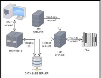
The solution architecture chosen for this project is depicted in Figure 7 It is composed of:
Fig. 7. Communication s equence in LMS-PFC [Own Elaboration]
LM S We bUI: A friendly Web Application to support the da ily requests made by final users. In this application the user can turn on or turn off devices, prepare illumination scenes, handle all the Master Data used in the system, among others.
LM S Engine: A Lightning Management Engine which is the responsible for the management and administration of Lightning Request to the P FC. It is also responsible for checking the actual state of devices and monitoring for problems in communication network.
LM S Se rvice: A Lightning Management Service, which was built to be watching for scheduled events the user may configure in the LMS WebUI.
complex environment, as depicted in Figure 8. It can be installed in a dedicated server, or each component can be installed in separated servers.
Fig. 8: Software Deploy Strategy. [Own Elaboration]
These features enhance the ability for the system to grow, adding computing resources or balancing load among various servers. The most important is the fact that each node can manage more than one PFC at the same time, giving scalability in a short time.
The system was also designed to be cloud-enabled. Multitenancy has been taken into account when designing the application, so that, whether a single company wanted to offers remote illumination management services to various companies, the system could support it.
The innovative fact was the ability of isolating communication with PFC´s (thought EtherNet/IP) on a single layer which can be called from the rest of the system components. This was done by exposing this layer as a Service. We made use of Software Design Patterns like SOLID and GoF to achieve this goal.
In fact, the system can be considered a Service Oriented Application using the SOA paradigm in which all components involved in it, communicate each other throught SOAP/HTTP. The service, which is a WCF (Windows Communication Foundation) service hosted in a Microsoft® Internet Information Server, receives the requests and handles communications with PFC. At the same time, this component is listening for errors in communication, devices failure, etc, to notify the users by e-Mail or On-Screen. This is shown in Figure 8
The system follows classic software design patterns. It was
built on three-tier paradigm architecture, also shown in Figure 9.
Fig. 9. Three-tier architecture. [Own Elaboration]
About security, the most important elements in this design were:
Not all people can access the
system(Authentication)
Not all people can access all features in the system. There must be roles and special permissions for access must be explicitly given to functionalities (Authorization)
In case of failure in the system, the actual state must reflect the real world state (Isolation).
There must be an audit trail to follow changes made in master data (Traceability)
Security in the solution was implemented using the security framework provided by Microsoft® for development in .Net Framework. This framework offers many web controls to help implementing security features ins ASP.Net applications. These web controls are the Login, Login View, Password Recovery, Login Status, Login Name, Create User, and Change Password Controls. These components have the ability to automate tasks in a web application. For doing this, we needed to develop a Custom Membership Provider and a Custom Role Provider, to handle the custom data we needed. Basic task (encryption, concurrence, etc) were handled in this layer too. This whole security layer allows centralizing security aspects of applications. This set of components fits well in the whole architecture developed.
stable state.
It was also useful to develop a software component into the whole architecture, in charge of follows changes to master data, and leave an audit trail which shows the whole sets of changes made to a particular data. It´s useful in corporate environments, where some roles can access the same data, make changes to it, and make themselves responsible for the changes made.
7. CONCLUSIONS
One of the main characteristics of the developed system, compared to those commercially offered, is its scalability and flexibility. The system could fit in any building, no matter its size. It can be managed through a web interface, designed specifically to systems administrators and final users to handle the illumination system, or by a remote wireless control, made for small users, and small installations, which cannot afford high investments in Technology and Infrastructure.
The development was leveraged by cutting-edge, low-cost technology, showing the possibility to make profitable developments based on these technologies in Colombia. It can boost new industries interested on strengthening its products.
The module created in this project is innovative. The next phase is to expand its scope so it can control intelligent and non-intelligent components in order to decrease costs in these type of systems.
For communication between LMS and PFC, it was important the creation and use of a proprietary protocol built over EtherNet/IP. This allows a secure and reliable communication channel across network to ensure correct operation of the whole system created.
The system can support any DALI-based device from any supplier. It gives flexibility to the system, since the user will not depend of a specific supplier. This fact adds value to the product.
This project is an initial step in a complete program for high-tech products development strategy focused on strengthening of national industry. We expect this system would be widely accepted to show many capabilities Colombia could have to develop this kind of systems.
REFERENCES
[1] CRAIG DILOUIE, 2010, Control Wiring: A Primer, Recuperado Abril 2012, de: http://lightingcontrolsassociation.org/control-wiring-a-primer/
[2] Own Doccument, “Sistemas de iluminación inteligente presentes en el Mercado de hoy, principales características, tecnologías
implementadas para su desarrollo y empresas
desarrolladoras.
[3] Open DeviceNet Vendor Association, Inc. (ODVA)., «EtherNet/IP
Quick Start for Vendors Handbook - A Guide
for EtherNet/IPTM Developers», 2008.
[Online]. Available:
http://www.odva.org/Portals/0/Library/Publications_Numbered/PU B00213R0_EtherNetIP_Develop ers_Guide.pdf. [Accessed:01-ago-2012].
[4] «THE CIP NETWORKS LIBRARY Volume 2 EtherNet/IP
Adaptation of CIP», nov-2007. [Online]. Available: ftp://ftp.heapg.com/AB-OCS/Ethernet%20IP%20CD/EtherNet-IP/Vol2_1.4.pdf. [Accessed:16-jul-2012].
[5] IEC 62386-101 “Digital addressable lighting interface requirements-System” – Part 101: General. International Electrotechnical Commission Edition 1.0 2009-06
[6] IEC 62386-102 “Digital addressable lighting interface requirements-Control gear” – Part 102: General. International Electrotechnical Commission Edition 1.0 2009-06
[7] IEC 62386-103 “Digital addressable lighting interface – Part 103: General requirements-Control devices”. International Electrotechnical Commission Edition 1.0 2010-07
[8] Amnon H. Eden, Tom Mens.“MeasuringSoftware Flexibility.” IEE Software, Vol. 153, No. 3 (Jun. 2006), pp. 113–126. London, UK: The Institutionof Engineering andTechnology.
[9] Available In
http://www.pcmag.com/encyclopedia/term/61437/security-suite
Alejandra Rojas Arias
Hardware Development Director at CIDEI, Bogotá, Colombia
Alejandra was born on June 21, 1986 in Bogota, Colombia, has a degree in Electronics Engineering from the University Francisco José de Caldas in Bogotá in December 2011, also has a master's degree in project management from the University of Barcelona, Spain.
She has worked for three years in development of electronic products in Colombia and is currently the project director of CIDEI in Bogota.
Manuel Alfredo Figueredo Medina Software Director at CIDEI, Bogotá, Colombia
Manuel was born on December 3, 1982 in Bogota, Colombia, has a degree in Chemical Engineering from the National University in Bogotá, also has a master's degree in System Engineering from the Andes University of Bogotá, Colombia
![Fig. 1. General System Architecture. [Own Elaboration]](https://thumb-us.123doks.com/thumbv2/123dok_us/1368408.1646562/2.612.68.276.103.313/fig-general-system-architecture-own-elaboration.webp)
![Fig. 3. Block structure of Unit Control [Own Elaboration]](https://thumb-us.123doks.com/thumbv2/123dok_us/1368408.1646562/3.612.309.593.56.235/fig-block-structure-unit-control-elaboration.webp)
![Fig. 4. Maintenance GUI. [Own Elaboration]](https://thumb-us.123doks.com/thumbv2/123dok_us/1368408.1646562/4.612.70.529.249.501/fig-maintenance-gui-own-elaboration.webp)
![Fig. 9. Three-tier architecture. [Own Elaboration]](https://thumb-us.123doks.com/thumbv2/123dok_us/1368408.1646562/6.612.66.607.94.319/fig-three-tier-architecture-own-elaboration.webp)
