Numerical Simulation of Forging Process for Steam
Turbine Blade
Chuan-wei Zhang
1, Lin-yang Li
2, Zhi-hui Zheng
31-3College of Mechanical Engineering, Xi’an University of Science and Technology, Xi’an Shaanxi 710054, China
Abstract-- AS is known to all, Steam turbine blade boundary layer is very thin, which requires higher surface roughness. In addition, the improper handling of the blade inlet and outlet side has a great influence on the aerodynamic performance. In order to solve the above problems, the blade machining method was adopted. DEFORM-3D and rigid plastic finite element method were used to analyze the forging process of steam turbine blade. Finally we got the maximum stress point tracking, a typical section of equivalent strain and load stroke curve. The results show that: Round section billet is a better choice.
Index Term-- Steam turbine blade, Rigid plastic finite element method, DEFORM-3D, Forging process
I. INTRODUCTION
Blade is the core component of steam turbine energy conversion. But the shape of the turbine blade is complex, which is one of the most difficult parts in the production
process[1-2]. Therefore, the die forging manufacturing ware
used to produce the turbine blade in the actual production process. However, the traditional steam turbine blade forging process is based on data or empirical formula to design, and we do not clear that the process of forging force and deformation, which will lead to blank design dimensions are not necessarily optimal, the products produced are easily not filled enough or appeared folding processing defects. In order to solve these problems, researchers need to spend a lot of
manpower and material resources, but the efficiency is low[3-4].
In recent years, with the rapid development of computer technology and finite element method, the numerical simulation method of metal plastic forming process has been studied and applied by domestic and foreign scholars and engineers. At present, the main methods of numerical simulation are principal stress method, slip method, energy method, N-S method, upper finite element method (UBET), finite element method (FEM), boundary element method and
so on. Liqiang An[5] et al. used the energy method to obtain the
eigenvalue equation of blade vibration frequency when the root constraint was random variable, and provided reference
for the numerical simulation of blade. Chao Gai[6] et al.
discussed the design of technological allowance for turbine blade forging, and optimized the die forging process by linear
decreasing method. Ran Shao[7] et al. take the elliptical shape
as the blade element model, and use the upper finite element method to simulate and analyze the forming of the blade. Although to some extent, optimize the process parameters, there is still a lot of room for improvement. To sum up, the above numerical simulation method has certain guiding significance for the research of steam turbine blade forging.
However, those methods don't take full into account the influence of the dynamic characteristics, various boundary conditions and initial conditions. Compared with other methods, the finite element method considers more comprehensively. Therefore, the finite element method is widely used in the numerical simulation of blade forging.
The elastic and plastic constitutive relation of metal material is very different, so the elastic-plastic material model and rigid plastic material model are formed. The corresponding plastic finite element method is divided into elastic-plastic finite element method and rigid plastic finite element method. Because the blade forging forming process is a bulk forming method, the rigid plastic finite element method
was adapted in this research[8-9]. By using the finite element
software-DEFORM, the turbine blade forging process was simulated. The maximum stress point tracking, a typical section of equivalent strain and load stroke curve could be got.
II. RESEARCH ELABORATIONS
The physical process of metal plastic deformation is very complex. In order to solve the problem, it is necessary to make some reasonable assumptions. The basic assumption could be list as follows:
(1) The plastic deformation of the material is much larger
than the elastic deformation, and the elastic deformation is neglected.
(2) The volume of material does not change before and after
deformation.
(3) Ignore the gravity and inertia of the material itself.
(4) Isotropic material.
(5) The material deformation obeys the Levy-Mises flow
theory and the material is isotropic hardening.
In this research, the turbine blade has a large deformation problem in the process of forging and forming, and the physical model of the turbine blade can be simplified into a rigid plastic model. The rigid plastic finite element method is based on the variational principle of rigid plastic material. It replaces the solution of the partial differential equations with functional extremum. It satisfies the following basic equations and boundary conditions.
(1) Equilibrium equation:
σij,j = 0 (1)
(2) The relationship between velocity and strain rate
i j ji
ij
u
,u
,2
1
In this formula, ui,j represents the speed; εij represents the
strain rate.
(3) Constitutive equation
ij
ij
(3)
In this formulaλ =3
2· 𝜀̅̇ 𝜎
̅, 𝜎̅represents equivalent stress;
𝜀̅̇𝑖jrepresents equivalent strain rate.
(4) Mises yield criterion[10]
2
2
1
K
ij ij
(4)In this formula, K = 1
√3 𝜎̅
(5) Volume incompressible boundary condition
0
iiv
(5)(6) Governing equations: stress boundary conditions and
velocity boundary conditions Stress boundary conditions
i j
ii
n
F
(6)Velocity boundary conditions
i
j
u
u
(7)(7) Markoff variational principle
Assuming a rigid plastic body, the volume is V, the surface
area of S, divided into the velocity surface Su and SF, Su given
a velocity of Vi, SF on a given surface force Fi. Satisfy all the
basic equations and boundary conditions of all the metal movement.
dS
V
F
dV
SF i i
V
(8)The absolute minimum is the first order variation of function is equal to 0, and the obtained velocity is the exact solution. The above formula represents the variational principle of rational rigid plastic materials. Its physical meaning: the plastic deformation rate of deformation is the first of the functional and the external force. Difference between the second items is the total energy consumption of rigid plastic body.
III.NUMERICAL SIMULATION OF BLADE FORGING PROCESS
The surface of blade is complex, and it is difficult to form in turbine blade forging process, if not reasonable blank shape, forging blade will appear a series of quality problems, such as edge, filling, crack, defect and the like. This paper studies the forging blade shape curve is relatively large, then choose the shape of the blank is relatively close to the blade shape round and oval, so blank in the process of deformation force is more uniform, less deformation of materials. The cross section of the blade body is shown in Figure 1(a). The shape and dimensions of the two types of blanks are shown in figure 1(b).
(b)
Fig. 1. The cross section of leaf and embryo
DEFORM-3D software does not have the function of drawing geometric model, therefore it needs SOLIDWORKS to build the upper die and a lower die and blank, and then, converting .STL format into DEFORM-3D software; DEFORM-3D Pre pre-processing for basic simulation settings. The setup process for pre-processing includes the following steps:
A. Basic Settings
The material used in the blade is high temperature resistant alloy material, 2Cr13 , The elastic modulus of the material at room temperature is 206GPa, Poisson's ratio is 2.5, Density is 7500Kg/m3, Yield strength is 440MPa. We choose a material similar to this material from the DEFORM-3D material model library, the material name is 21-21N-Stainless, Simulated
temperature is 1100℃.
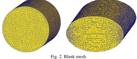
B. Mesh Partition
In the simulation process, the focus is on the deformation of the billet. Upper and lower modes are assumed to be rigid bodies without any deformation, so they do not need to mesh. We just need to mesh the blanks. The increase of the number of grid elements can improve the simulation accuracy of stress and strain, but the calculation time is longer. Comparing the number of grid elements, the number of grid elements of circular section and elliptical section was respectively determined to be 34100 and 34102. It is shown in figure2.
Fig. 2. Blank mesh
Due to the contact between the blank and the upper and lower die, it will continue to force, and a large deformation.
DEFORM is used to deal with this problem[11-12]. It will
automatically process the mesh refinement at the boundary.
C. Boundary Condition Setting
DEFORM-3D software provides two kinds of friction
model that is shear friction and Kulun friction[13]. The contact
D. The Setting of Mould Motion Parameters
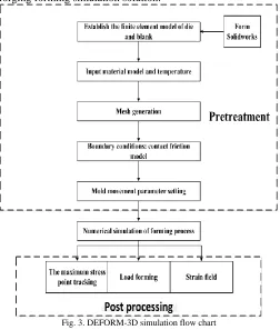
The upper die is used as the motion module, set its motion speed at 40mm/s. The lower die is fixed. Measurement of the distance of the upper mold with a ruler under the distance of 52mm, set the number of simulation steps for 200 steps, each step given a certain distance of 0.26mm, the total travel distance is equal to the number of steps multiplied by the step size. Storage increment is 10, this means to save every 10 steps, each step can avoid the preservation of data caused by large files. Then open the STOP dialog box, chose die distance option, and then the graphics window with the mouse to select a point on the mold, Finally, filled the distance between the two dies in the distance box at the end of the static time. As shown in figure 3, we could see the specific process of blade forging forming simulation solution.
Fig. 3. DEFORM-3D simulation flow chart
IV. RESULTS AND ANALYSIS
In the process of plastic deformation of blade forging, it is assumed that the volume of the circular and elliptical blanks is equal before and after the deformation. The volume of the above two blanks are 39760.782 cubic millimeter and 39770.393 cubic millimeter, the difference is only 0.02%.
A. The Naximum Stress Point Tracking Analysis
In this paper, the maximum stress of the five section of the circular section and the elliptical section of the billet are analyzed. The results are shown in Figure 4(a) and 4(b).
(a) The maximum stress of round cross section stress track map
(b) The maximum stress of elliptical cross section stress track map Fig. 4. The maximum stress track map
As is shown in figure4, 1, 2, 3, 4, 5 are the peak stress of axial equal distance cross section. It can be seen from the figure that the circular section is in contact with the upper and lower die in 0.008s, the contact force is relatively early, and the contact is even. During the deformation process, the stress is uniform and the maximum stress is 238MPa. The blank of the elliptical section and the upper and lower die contact with the upper and the lower die in 0.04s, but the stress fluctuates greatly at 0.1s, the contact between the blank and the die is obviously uneven, and the metal is irregular. The stress in the section where the 0.12s is located at the point of 5 is suddenly reached the maximum stress of 269MPa. The production of such a large stress requires a greater pressure on the forging of the screw press. To sum up, the circular cross section billet is contacted more early and more uniform than the oval cross section, and the forging load needed in the forging process is relatively small.
B. Analysis of Equivalent Effect of Typical Section
(a) Equivalent strain diagram of round cross section
(b) Equivalent strain diagram of elliptical cross section Fig. 5. Equivalent strain diagram
As is shown in figure5, the fins of round cross section is less then elliptical cross section, and the steam side can fill the model. The material with circular cross section is uniform and the stress distribution is uniform too. It can be seen that the fins of circular section billet is smaller than that of oval section, and the material is saved, and the stress, deformation distribution is even.
C. Load Stroke Curve Analysis
Circular, elliptical cross section blank load stroke are shown in Figure 6(a),(b).
(b) Elliptical cross section blank load stroke curve diagram Fig. 6. load stroke curve
The load of round section billet increases linearly with time, and the maximum forging pressure is 622KN.The loading of the elliptical section billet increases exponentially with time, and the maximum forging pressure is 1850KN. The circular section blank is smaller than the oval cross section blank the biggest forging pressure, so the upper and lower mold damage is smaller.
V. CONCLUSIONS
DEFORM-3D software was used to simulate the forging process of turbine blade, and got the maximum stress point tracking, a typical section of equivalent strain and load stroke curve. It could be concluded that the blank of circular section is more suitable for contact with the upper and lower die during the forging forming process, the stress distribution is more uniform in the cavity, the required forging pressure is more uniform and the maximum forging pressure is 622KN; The forging pressure is small, and the forging process is obviously less. When the blade is improved after forging, the circular section blank is better choice. And when the blank is actually manufactured, the circular section blank is better processed and saved.
ACKNOWLEDGMENT
This work was financially supported by the Science research project of Shaanxi Provincial Department of Education (11JK0869). Meanwhile, it was financially supported by Xi'an University of Science and Technology.
REFERENCES
[1] L. Yang, S. T. Zhao and W. Wu, “Research and Practice on integrated processing technology of steam turbine blade,” Tool Engineering, vol. 2, pp. 134–137, Feb. 2016.
[2] J. Baran, “Redesign of steam turbine rotor blades and rotor packages – Environmental analysis within systematic eco-design approach”, ELSEVIER Journal of Energy Conversion and Management, vol. 116, pp. 18–31, May. 2016.
[5] L. Q. An, Z. Q. Wang and Z. Z. Peng, “A probabilistic analysis for static and dynamic frequency of blade with uncertain restriction,” Proceedings of The Chinese Society for Electrical Engineering, vol. 25, pp. 86–90, Oct. 2005.
[6] C. Gai and M. J. Zhang, “Designing of Machining Allowance Blade in Turbine of Die Forging,” Chinese Journal of Hot Working Technology, vol. 37, pp. 76–79, Aug. 2008.
[7] R. Shao and K. Xu, "Study on Blade Forging Die Design Based on Deform-3D,” Chinese Journal of Hot Working Technology, vol. 43, pp. 148–150, Mar. 2014.
[8] D. Hao, “Study on improving the machining efficiency of steam turbine blade,” Chinese Journal of Mechanical Engineer, vol. 53, pp. 151–153, Mar. 2016.
[9] J. Liu, W. Sheng, and L. Hou, “Numerical simulation and process optimization of steam turbine blade forging,” Chinese Journal of Metal Working, vol. 11, pp. 38–40, May 2016.
[10] N. Aleksandrova, “Application of Mises yield criterion to rotating solid disk problem,” International Journal of Engineering Science, vol. 51, pp. 333–337, Feb. 2012.
[11] B. Sreenivasulu, G. Prasanthi, “FEA Simulation Analysis of Tube Hydroforming Process Using DEFORM-3D,” Procedia Engineering, vol. 97, pp. 1187–1197, Dec. 2014.
[12] Włodzimierz Wróblewski, “Numerical evaluation of the blade cooling for the supercritical steam turbine,” Applied Thermal Engineering, vol. 51, pp. 953–962, Mar. 2013.
[13] T. Tanuma, “Design and analysis for aerodynamic efficiency enhancement of steam turbines,” Advances in Steam Turbines for Modern Power Plants, vol. 6, pp. 109–126, Feb. 2017.
AUTHORS
First Author – Chuan-wei Zhang: male, Ph.D., Professor of Xi'an University of Science And Technology. Committee member of China Institute of automation manufacturing technology Specialized Committee and the Chinese society of metals ferroalloy branch; Member of China Mechanical Engineering Society; Research interests: modern electric vehicle control technology and intelligent control of mechanical and electrical system.
E-mail address: [email protected]
Second Author– Lin-yang Li: male, Master student, College of mechanical engineering, Xi'an University of Science And Technology, Major in Mechanical Engineering.
E-mail address: [email protected](corresponding author)
Third Author – Zhi-hui Zheng: female, Master, College of mechanical engineering, Xi'an University of Science And Technology, Major in Mechanical Engineering.