e-ISSN: 2278-7461, p-ISSN: 2319-6491
Volume 5, Issue 6 [June 2016] PP: 10-18
Single Point Incremental Forming and Significance of Its Process
Parameters on Formability of Conical Cups Fabricated from
AA1100-H18 Alloy
T. Santhosh Kumar
1and A. Chennakesava Reddy
21PG student, Department of Mechanical Engineering, JNTUH College of Engineering, Kukatpally, Hyderabad –
500 085, Telangana, India 2
Professor, Department of Mechanical Engineering, JNTUH College of Engineering, Kukatpally, Hyderabad – 500 085, Telangana, India
Abstract: -The purpose of the present project work was to determine the formability of AA1100-H18 alloy to fabricate conical cups using single point incremental forming (SPIF) process. The finite element analysis has been carried out to model the single point incremental forming process using ABAQUS software code. The process parameters of SPIF were sheet thickness, step depth, tool radius and coefficient of friction. The process parameters have been optimized using Taguchi techniques. As per R2 values, all process parameters influence the output characteristics of single point incremental forming process of AA1100-H18 alloy.
.
Keywords: -AA1100-H18 alloy, conical cup, single point incremental forming, finite element analysis, step depth, tool radius, sheet thickness, coefficient of friction.
I.
INTRODUCTION
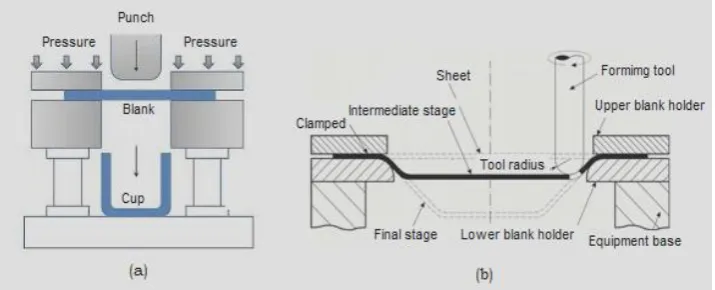
A lot of research is available on the formability of deep drawing process for various materials using traditional deep drawing process with forming dies. Several materials such as AA1050 alloy [1], AA1070 alloy [2], AA1080 alloy [3], AA1100 alloy [4], AA2014 alloy [5], AA2017 alloy [6], AA2024 alloy [7], AA2219 alloy [8], AA2618 alloy [9], AA3003 alloy [10], AA5052 alloy [11], AA5039 alloy [12], Ti-Al-4V alloy [13], EDD steel [14], gas cylinder steel [15] were also tested for superplasticity for deep drawing of cups. In recent years, the cup drawing process is also extended to single-point incremental forming (SPIF) process [16]. The SPIF process is a die less configuration. This process uses a smooth ended tool under CNC control to create a local indentation on a clamped sheet, and by moving the point of contact around the sheet according to a programmed tool path. The difference of traditional and SPIF processes is shown in Fig.1. In traditional deep drawing process, the shape of end product is controlled by the forming die. In incremental deep drawing process, the shape of end product is obtained by the tool path.
Fig. 1 Difference of (a) traditional and (b) incremental deep drawing processes.
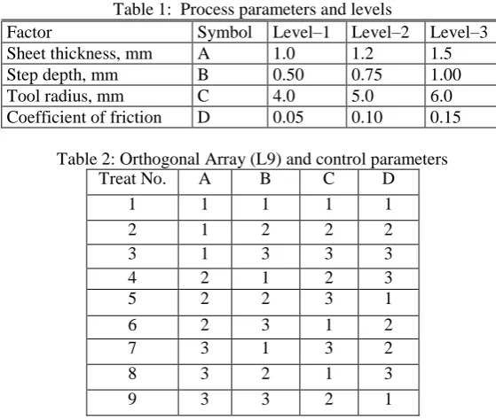
Table 1: Process parameters and levels
Factor Symbol Level–1 Level–2 Level–3 Sheet thickness, mm A 1.0 1.2 1.5 Step depth, mm B 0.50 0.75 1.00 Tool radius, mm C 4.0 5.0 6.0 Coefficient of friction D 0.05 0.10 0.15
Table 2: Orthogonal Array (L9) and control parameters Treat No. A B C D
1 1 1 1 1 2 1 2 2 2 3 1 3 3 3 4 2 1 2 3 5 2 2 3 1 6 2 3 1 2 7 3 1 3 2 8 3 2 1 3 9 3 3 2 1
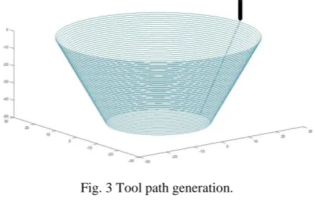
The sheet and tool geometry were modeled as deformable and analytical rigid bodies, respectively, using ABAQUS. They were assembled as frictional contact bodies. The sheet material was meshed with S4R shell elements (Fig. 2a). The fixed boundary conditions were given to all four edges of the sheet as shown in Fig. 2b. The boundary conditions for tool were x, y, z linear movements and rotation about the axis of tool [21]. True stress-true strain experimental data were loaded in the tabular form as material properties. The tool path geometry was generated using CAM software [22] was imported to the ABAQUS as shown in Fig. 3. The elastic-plastic deformation analysis was carried out for the equivalent stress, strain and strain rates and thickness variation.
Fig. 3 Tool path generation.
III.
RESULTS
AND
DISCUSSION
F-tests arises by considering a decomposition of the variability in a collection of data in terms of sums of squares. In this work, the Fisher’s test was confirmed to accept all the parameters (A, B, C and D) at 90% confidence level. If the percentage contribution of process parameters is less than 10%, they are considered as less significant.
3.1 Influence of process parameters on effective stress
Table – 3 gives the ANOVA (analysis of variation) summary of effective stress data. All the process parameters were significant. The contributions are 45.81%, 23.75%, 16.52% and 13.90%, respectively of sheet thickness, coefficient of friction, tool radius, step depth. The step depth makes the least contribution towards the effective stress.
Table 3: ANOVA summary of the effective stress.
Source Sum 1 Sum 2 Sum 3 SS v V F P A 846.9 822.4 858.5 226.4325 1 226.44 30191.9997 45.81 B 852.9 832.6 842.3 68.7125 1 68.72 9162.66666 13.9 C 841.9 831.9 854 81.6325 1 81.64 10885.3332 16.52 D 851 827.3 849.5 117.4025 1 117.41 15654.6665 23.75
e 0.03 4 0.0075 1.00000 0 T 3392.7 3314.2 3404.3 494.21 8 100
Note: SS is the sum of square, v is the degrees of freedom, V is the variance, F is the Fisher’s ratio, P is the percentage of contribution and T is the sum squares due to total variation.
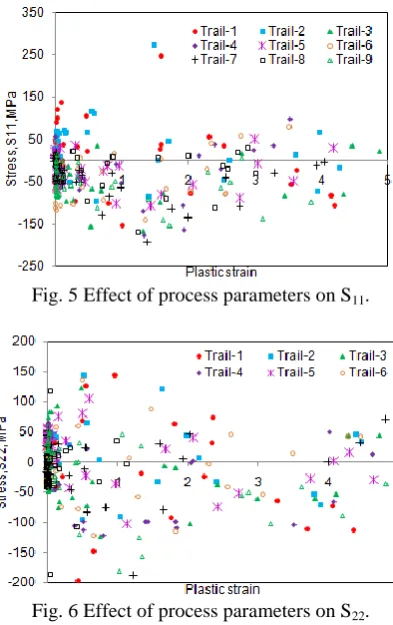
Fig. 5 Effect of process parameters on S11.
Fig. 6 Effect of process parameters on S22.
The principal stresses S11, S22 and shear stress S12 are shown in Figs. 5, 6 and 7 respectively. The
densities of compressive stresses induced in the sheet are higher in number than the tensile stresses. The deformation is of compression type for the strain less than 4.0 and it is tensile for the strain greater than 4.0. The shear stress developed in the blank sheet is less than 50% of S11 or S22.
Fig. 7 Effect of process parameters on S12.
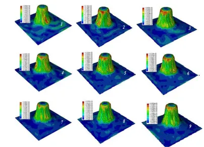
Fig. 8 Raster images of von Mises stress in the cups.
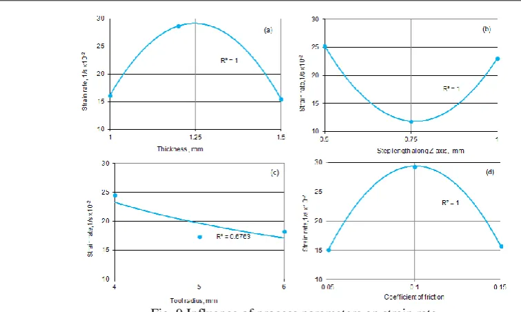
3.2 Influence of parameters on strain rate
The ANOVA summary of the strain rate is given in Table 4. The percent contribution column establishes the most significant process parameters are coefficient of friction, sheet thickness and step depth. Their contributions are 34.69%, 29.40%, and 27.71% towards variation in the strain rate. The less significant process parameter is the tool radius.
Table 4: ANOVA summary of the strain rate
Source Sum 1 Sum 2 Sum 3 SS v V F P A 48.39 85.96 46.408 331.0919 1 331.09 172532.56 29.4 B 75.96 35.578 69.22 312.0019 1 312 162584.679 27.71 C 73.748 52.11 54.9 92.36192 1 92.36 48129.2398 8.2 D 45.3 88.18 47.278 390.6219 1 390.62 203553.937 34.69
e -0.00768 4 -0.00192 1.00000 0 T 243.398 261.828 217.806 1126.062 8 100
Fig. 9 Influence of process parameters on strain rate.
3.3 Influence of parameters on thickness reduction
The ANOVA summary of the thickness reduction is given in Table 5. In the decreasing order of contribution, step depth, sheet thickness, tool radius and coefficient of friction furnish, respectively, 32.08%, 24.50%, 24.47% and 18.93% towards variation in the thickness reduction.
Table 5: ANOVA summary of the thickness reduction
Source Sum 1 Sum 2 Sum 3 SS v V F P A 252.826 256.588 247.119 15.16 1 15.16 9602.651 24.5 B 247.504 250.856 258.175 19.85 1 19.85 12573.39 32.08 C 248.041 251.103 257.389 15.14 1 15.14 9589.982 24.47 D 251.554 256.647 248.333 11.71 1 11.71 7417.351 18.93
e 0.00631 4 0.001579 1 0
T 999.924 1015.19 1011.02 61.8664 8 100
The reduction of sheet thickness was very low for large sheet thickness as seen from figure 10a. The reduction in thickness was increased with increase of steep depth (Fig. 10b). Also, the thickness reduction was increased with tool radius (Fig. 10c). The thickens reduction was high for the coefficient of friction of 0.1 (Fig. 10d). In all above cases, the R-squared value is above 0.95. There is an agreement between observed and modeled values. All the process parameters are a cause of the changes in the reduction of thickness. The reduction of thickness was considered at the center-line of the deformed cup as shown in Fig. 11a. As observed from Figs. 11b-d, the majority of thickness reduction takes place in the upper part walls of the cup but not in the flange or bottom or lower part of walls of the cup. The elements located above the mid regions of the cup walls were elongated higher than those present at below the mid regions of the cup walls.
Fig. 11 (a) Location of thickness reduction in the deformed cup and (b) to (d) Effect of process parameters on thickness reduction
Fig. 12 Forming limit diagrams: (a) for trials 1, 2, 3, (b) for trials 4, 5, 6 (c) for trials 7, 8, 9 and (d) forming limit diagram of deep drawing process.
3.4 Formability of SPIF process
sectioning R&D project.
REFERENCES
[1] Reddy, A. C. Homogenization and Parametric Consequence of Warm Deep Drawing Process for 1050A Aluminum Alloy: Validation through FEA. International Journal of Science and Research, 2015, 4 (4), pp. 2034-2042.
[2] Chandini, K.; Reddy, A. C. Finite Element Analysis of Warm Deep Drawing Process for Pyramidal Cup of AA1070 Aluminum Alloy. International Journal of Advanced Research, 3(6), 2015, pp. 1325-1334. [3] Yamuna, B.; Reddy, A. C. Finite Element Analysis of Warm Deep Drawing Process for Conical Cup of
AA1080 Aluminum Alloy. International Journal of Advanced Research, 3(6), 2015, pp. 1309-1317. [4] Srinivas, T.; Reddy, A. C., Finite Element Analysis of Warm Deep Drawing Process for Rectangular Cup
of AA1100 Aluminum Alloy. International Journal of Advanced Research, 3(6), 2015, pp. 1383-1391. [5] Reddy, A. C. Parametric Optimization of Warm Deep Drawing Process of 2014T6 Aluminum Alloy
Using FEA. International Journal of Scientific & Engineering Research, 6(5), 2015, pp.1016-1024. [6] Reddy, A. C. Finite Element Analysis of Warm Deep Drawing Process for 2017T4 Aluminum Alloy:
Parametric Significance Using Taguchi Technique. International Journal of Advanced Research, 3(5), 2015, pp. 1247-1255.
[7] Reddy, A. C. Parametric Significance of Warm Drawing Process for 2024T4 Aluminum Alloy through FEA," International Journal of Science and Research, 4(5), 2015, pp. 2345-2351.
[8] Reddy, A. C. Formability of High Temperature and High Strain Rate Superplastic Deep Drawing Process for AA2219 Cylindrical Cups. International Journal of Advanced Research, 3(10), 2015, pp. 1016-1024. [9] Reddy, A. C. High temperature and high strain rate superplastic deep drawing process for AA2618 alloy
cylindrical cups," International Journal of Scientific Engineering and Applied Science, 2(2), 2016, pp. 35-41.
[10] Reddy, A. C. Practicability of High Temperature and High Strain Rate Superplastic Deep Drawing Process for AA3003 Alloy Cylindrical Cups. International Journal of Engineering Inventions, 5(3), 2016, pp. 16-23.
[11] Reddy, A. C. Suitability of High Temperature and High Strain Rate Superplastic Deep Drawing Process for AA5052 Alloy. International Journal of Engineering and Advanced Research Technology, 2(3), 2016, pp. 11-14.
[12] Reddy, A. C. High temperature and high strain rate superplastic deep drawing process for AA5049 alloy cylindrical cups. International Journal of Engineering Sciences & Research Technology, 5(2), 2016, pp. 261-268.
[13] Reddy, A. C. Finite element analysis of reverse superplastic blow forming of Ti-Al-4V alloy for optimized control of thickness variation using ABAQUS. Journal of Manufacturing Engineering, 1(1), 2006, pp.6-9.
[14] Reddy, A. C.; Reddy, T. K. K.; Vidya Sagar, M. Experimental characterization of warm deep drawing process for EDD steel. International Journal of Multidisciplinary Research & Advances in Engineering, 4(3), 2012, pp.53-62.
[15] Reddy, A. C. Evaluation of local thinning during cup drawing of gas cylinder steel using isotropic criteria. International Journal of Engineering and Materials Sciences, 5(2), 2012, pp.71-76.
[16] Jeswiet, J.; Micari, F.; Hirt, G.; Bramley, A.; Duflou, J.; Allwood, J. Asymmetric Single Point Incremental Forming of Sheet Metal. CIRP Annals - Manufacturing Technology, 54 (2), 2005, pp. 88-114.
[18] Liu, Z.; Liu, S.; Li, Y.; Meehan, P. Modeling and optimization of surface roughness in incremental sheet forming using a multi-objective function. Materials and Manufacturing Processes 29 (7), 2014, pp. 808– 818.
[19] Radu, M.C.; Cristea, I. Processing metal sheets by SPIF and analysis of parts quality. Materials and Manufacturing Processes, 28 (3), 2013, pp. 287–293.
[20] Nguyen, D.T.; Park, J.G.; Lee, H.J.; Kim, Y.S. Finite element method study of incremental sheet forming and its improvement for complex shape. Proceedings of the Institution of Mechanical Engineers, Part B: Journal of Engineering Manufacture, 224 (6), 2010, pp. 913–924.
[21] Alavala, C. R. CAD/CAM: Concepts and Applications, PHI Learning Pvt. Ltd, 2008.
[22] Alavala, C. R. Finite element methods: Basic Concepts and Applications, PHI Learning Pvt. Ltd., 2008. [23] Reddy, A. C. Formability of Warm Deep Drawing Process for AA1050-H18 Pyramidal Cups.
International Journal of Science and Research, 4(7), 2015, pp. 2111-2119.
[24] Reddy, A. C. Formability of Warm Deep Drawing Process for AA1050-H18 Rectangular Cups. International Journal of Mechanical and Production Engineering Research and Development, 5(4), 2015, pp. 85-97.