http://www.sciencepublishinggroup.com/j/ep doi: 10.11648/j.ep.20180202.11
ISSN: 2640-1010 (Print); ISSN: 2640-1029 (Online)
Reliability-Based Structural Safety Evaluation of
Concrete-Steel Composite Beams
According to Euro Code 4
Abubaka Mamuda
1, *, Idris Abubakar
2, Duna Samson
11
Department of Civil Engineering, Faculty of Engineering, Abubakar Tafawa Balewa University, Bauchi, Nigeria 2Department of Civil Engineering, Faculty of Engineering, Ahmadu Bello University, Zaria, Nigeria
Email address:
*Corresponding author
To cite this article:
Abubaka Mamuda, Idris Abubakar, Duna Samson. Reliability-Based Structural Safety Evaluation of Concrete-Steel Composite Beams
According to Euro Code 4. Engineering Physics. Vol. 2, No. 2, 2018, pp. 32-40. doi: 10.11648/j.ep.20180202.11
Received: October 11, 2018; Accepted: November 1, 2018; Published: November 27, 2018
Abstract:
Uncertainties are always present in Analysis and design of Engineering systems, but conventional approach simplify the problem by considering the uncertain parameters to be deterministic in which are not and accounted for the uncertainties through the use of empirical safety factors which are derived based on experience. In this study, reliability analysis of Concrete-Steel Composite Beams was carried According to Euro code using First Order Reliability Method (FORM) through a developed matlab programme, four failure mode considered are bending, shear, deflection and shear connectors capacity, by considering loads and resistances variables of the sections in the limit state equations to be random. The analysis was carried out by varying some parameters while keeping other parameters constant, and this is to study the effects of the parameters against one another. The safety index was found to be affected by parameters like steel yield strength concrete strength, effective width of the slab, web thickness, ultimate tensile strength, shank diameter of the shear connectors, Load ratio, live load and span of the beam. From the failure mode considered, Euro code 4 seems to be conservative with respect to shear, safe with respect to deflection, satisfactory to bending, while shear studs capacity was at critical.Keywords:
Reliability, Composite Beam, Limit State, Load Ratio, Tensile Strength, Effective Width, Safety Index1. Introduction
Engineers have always recognized the presence of uncertainties in analysis and design of engineering systems. However, traditional approaches simplify the problem by considering the uncertain parameters to be deterministic and accounting for the uncertainties through the use of empirical safety factors [1]. Safety factors are derived based on past experience but do not absolutely guarantee safety or satisfactory performance. Also, they do not provide any information on how the different parameters of the system influence safety [2-4].
Therefore; it is difficult to design a system with a uniform distribution of safety levels among the different components using empirical safety factors as loading and load carrying capacity of structural members are random variables not deterministic, as normally assumed [5].
These lead to revision of several codes and design
guidelines to incorporate probabilistic analysis. Such revised codes include the American Institute of Steel Construction Load and Resistance Factor Design (1994) specifications and Canadian structural design specifications [6-7]. The use of reliability analysis in these codes was to provide more information about system behaviour, the influence of different uncertain variables on system performance, and the interaction between different system components.
Modern structures require more critical and complex designs, thus the need for accurate approach to assess uncertainties using computer models, loads, geometry, material property and manufacturing process [8]. However, to manage and accommodate the effects of uncertainties on structural performance, different methods of reliability-based design have been developed through which load and resistance variable were considered random and stochastic [9-12].
technique that can efficiently find the global solution, and a structural analysis tool that can accurately evaluate the stresses of complicated composite structures [13].
In order to use more rational way to evaluate the level of safety associated with composite beam design, this study uses reliability based study by considering the load and resistance variables to be random, and analyse the limit state functions through a developed MATLAB programme [14] according to Eurocode 4 [15].
1.1. Composite Beam
EC4 defined composite beam as a structural member with components of concrete and either of structural or cold-formed steel, connected by shear connectors. The shear connectors aim to limit the longitudinal slip between the two materials and the separation of one component from the other and they are subjected mainly to bending [16-17]. Full composite action can be achieved by welding the shear studs to the top flange of the steel beams and embedding the studs in the concrete when cast [18-19]. Figure 1 shows how shear stud is being connected at the top flange of steel beam.
Figure 1. Shear stud welded to the flange of steel beam [20].
It can be seen from figure 2 (a) for a composite beam there is an interaction between the two materials while figure 2 (b) there is no interaction between the two materials therefore the stress behaviour of the materials are independent to one another
Figure 2. Composite Behaviour of Concrete-Steel Beams [15].
1.2. Section Classification, Analysis, and Resistance
Table 1 shows the different classes of sections and their method of analysis with the type of section resistances as far [15].
Table 1. Section Classification.
Class of Section Type of Analysis Creep, Shrinkage, Cracking Resistances
1 Rigid plastic or elastic theory with moment redistribution No` Plastic
2 Elastic theory with moment redistribution No Plastic
3 Elastic theory Yes Elastic
4 Elastic theory yes Elastic acc. To EN 1993-1-5
1.3. Basic Concept of Reliability
Reliability concept has been perceived as an instigating issue for a long period [5]. The main aim of engineering is to provide a minimum level of safety and serviceability throughout the structure’s life time. But due to the vital source of uncertainties that could lead to under- or over- design make it a difficult task to achieve. For instance uncertainties related to loading, material properties, engineering models, environmental exposure etc. it is through reliability analysis method that a theoretical frame
and a comprehensive decision scheme for considering uncertainties work is offered [21].
1.4. Need for Reliability Evaluation
method is usually applied, which account for uncertainties by use of empirical safety factor. While system with high level of uncertainty stochastic approaches are necessary in its analysis and design [5-22]. Deterministic approach does not directly take care of randomness nature of the design variables and it may lead to under estimation of such uncertainties and consequently result in collapse of the system or structure [23].
1.5. First Order Reliability Method Procedure
The main objective of structural reliability is to ensure that no matter how the loading S it should not exceed the strength or resistance R throughout the structures life [10].
Meaning that then safety margin can be define by equation 1 below
Z = R-S (1) If both the loading and resistance are random variables, Z is also random variable with failure correspond to the condition (Z ˂ 0) In this case, if the probability distribution associated with Z is known the failure probability Pf can be easily computed as:
Pf = p (R˂S) = p(R-S˂0) (2)
For statically independent R and S following normal distribution, Z is also normally distributed with mean µZ, and
standard deviation σz
µZ = µR – µS (3)
σz = σ σ (4)
where µR, µs, σR and σs are mean and stadard deviations of
variables R and S respectively. The probability of failure can be express as
Pf = Φ (–β) = 1- Φ (–β) (5)
Where Φ is the cumulative distribution of standard normal variable and β is the ratio called reliability index
β = µZ / σZ =
(6)
As may be easily seen from Figure 2, the reliability index computed by FOSM represents the number of standard deviations that separate the mean value of the performance function from the limit state surface Z = 0.
For lognormal random variables, an alternative formulation to equation 5 could be derived as follows: Assume that R and S are statically independent lognormal random variable Y can be introduced as
⁄ (7) Or
ln Y Z ln R – ln S (8)
Figure 3. Probability density function of safety margin Z and failure probability Z˂0 [21].
The failure event can be defined as Y < 1.0 or Z < 0. Since R and S are lognormal, lnR and lnS are normal; therefore, lnY
or Z is a normal random variable with mean λR – λS and
standard deviation
ξ
"ξ
". The probability of failure can be defined similar to equation 5.# $ %&'( '( )* )*+ $ ,-./0/1 $ -2 (9)
In the general case where the performance functions Z is a function of a vector of n random variables, i.e.
Z = g(X) = g(X1, X2…, X (10)
The Taylor series expansion about the mean value gives
3 4 μ6 ∑<=>?8:;89 (Xi−µXi) + ?∑ ∑<=>? <=>?86= 86@8 9 (Xi−µXi)
(Xi−µXi) + … (11)
Where the derivatives are evaluated at the mean values of the random variables (X1, X2,… Xn), and µXi is the mean
value of Xi
2. Methodology
The reliability analysis was carried out on 300 X 300 X 42.2 kg IPE beam section supporting a concrete slab of 150 mm thickness using First Order Reliability Method through a developed matlab programme, with four limit state functions for the four failure mode considered bending, shear, deflection and shear connectors capacity, by considering loads and resistances variables of the sections in the limit state equations to be random.
The mode of failure considered in the limit state design of the composite beam involve
1.Bending failure mode 2.Shear failure mode 3.Deflection failure mode 4.Shear connection failure mode The performance functions are: Considering bending
4 A BCD, F- BF (12) Therefore,
Where;
FY is yield strength of structural Steel
ht is the depth of concrete slab
hg is depth of centre of steel section from top of steel
flange.
θR = is the uncertainty in resistance model
θS = is the uncertainty in load model
α = is the dead to live load ratio
Y \Z[
[
Considering shear
4 A ]CD, F- ]F (14) Therefore,
4 A G 0.6`aJK- 0.5 c 1.35Y 1.5 \fc g c G (15)
Considering deflection
4 A G - 5hgin384lmG (16)
Considering Shear resistance of the shear stud
4 A o- ]F (17) Therefore,
4 A G &.Xpqro in
st - 0.5 c 1.35Y 1.5 \fc g c G (18)
Where;
u
v Partial safety factor for the shear stud =1.25 d is shank diameter of the studFu is Ultimate tensile strength of shear stud
in evaluating the deflection of the beam, the section have to be transformed in to equivalent steel section by applying a modular ratio as stated in Euro code, and is 10 and 15 for normal and light weight concrete respectively, and the moment of inertia I in equation 19 is the gross moment of inertia of the composite section as given in equation 19 below
mN mI wxi~w• xyzz{|{yzz} {{||€ (19)
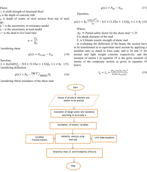
Figure 4. Reliability analysis flow chart.
3. Results and Discussions
The analysis was carried out by varying some parameters like the slab thickness, web thickness, width of the concrete slab, live loads, concrete strength steel strength and load ratio while keeping other parameters constant, and this is to study the effects of the parameters against one another. The analysis results are;-
3.1. Bending
Figure 5. Reliability Index against Beam Span at different live loads for Fy = 275 N/mm2 considering bending.
Figure 6. Reliability Index against Beam Span at different live loads for Fy = 355 N/mm2 considering bending.
Figure 7. Reliability Index against Beam Span at different live loads for Fy = 460 N/mm2 considering bending.
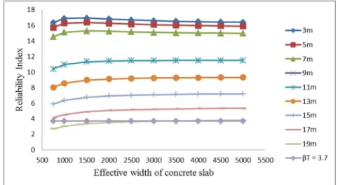
It was observed from figure 8 at varying effective width of concrete slab, the optimum reliability index was found to be at 1500 mm effective width at 3 to 7 m beam span but for 9 m the optimum is at 2000 mm. and it was observed that all are at above one-fourth of the span as recommended by Euro code [15]. However, the safety index keep increasing with increase in effective width of the slab at 13 to 25 m beam span.
Figure 8. Reliability Index against Effective width of concrete slab at Qk = 4kN/m at different beam span for grade S460 considering bending.
From figure 9, 10 and 11, an increase in safety index with increase in slab thickness was observed,
and in both the three steel strength for 200 mm thickness and above all of points passes the target reliability of 3.3 to 3.7 for structures of minor to large consequences of failure as recommended by both Joint Committee on Structural Safety and Eurocode [15, 24]. The safety index also increase with increase in steel strength with all the point passes the minimum safety index for Fy = 460N/mm2 and only one point
doesn’t pass for Fy = 355N/mm2 and nine points for
Fy = 275N/mm2, but the safety decreases with increase in
load ratio.
Figure 9. Reliability Index against Slab Thickness at Qk = 4kN/M at Different Load Ratio for Fy = 275 N/mm2 and 11m Beam Span considering bending.
Figure 11. Reliability Index against Slab Thickness at Qk = 4kN/M at Different Load Ratio for Fy = 460 N/mm2 and 11m Beam Span considering bending.
3.2. Shear
figure 12, 13, and 14 present the reliability indexes at different live loads and beam span for Fy = 275, 355 and 460
N/mm2 steel strength respectively considering shear failure. The safety index was found to be decreasing with increase in both live loads and beam span, but increases with increase in the steel strength
Figure 12. Reliability Index against Beam Span at different live loads for Fy = 275N/mm2 considering shear failure.
Figure 13. Reliability Index against Beam Span at different live loads for Fy = 355 N/mm2 considering shear failure.
Figure 14. Reliability Index against Beam Span at different live loads for Fy = 460 N/mm2 considering shear failure.
Also an increase in safety index was observed with increase in web thickness but decreases with increase in load ratio as presented in figure 15. All the points pass the target safety index of 3.7 for Fy = 460N/mm2 and only at 25m beam
span with 10kN/m live load does not pass for Fy = 355N/mm2
however, 4 points at 19 to 25m beam span with 10kN/m live load doesn’t pass for Fy = 275N/mm2 as recommended target
reliability by both by both Joint Committee on Structural Safety and Eurocode [15, 24].
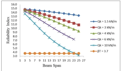
3.3. Deflection
Figure 16 present the results for reliability indexes at different live loads and beam span considering deflection limit state, the safety index was found to be decreasing with increase in both live loads and beam span and it’s found to be critical when the span reaches 21 m 15 m, 13 m, and 11 m for a live loads of 1.5kN/m, 3 kN/m, 5 kN/m, and 9 kN/m respectively a.
Figure 16. Reliability Index against Beam Span at different live loads considering deflection failure.
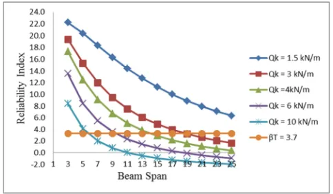
3.4. Shear Stud Capacity
the results for reliability indexes at different live loads and beam span considering shear stud capacity was presented in figure 17, 18 and 19 for Fy = 275, 355 and 460 N/mm2 steel
strength respectively, the safety index was also found to be decreasing with increase in both live loads and beam span, but increases with increase in the steel strength.
Figure 17. Reliability Index against Beam Span at different live loads for grade Fy = 275 N/mm2 considering shear stud failure.
Figure 18. Reliability Index against Beam Span at different live loads for Fy = 355 N/mm2 considering shear stud failure.
Figure 19. Reliability Index against Beam Span at different live loads for Fy = 460 N/mm2 considering shear stud failure.
It was observed from figure 20, that the reliability index increases with increase in shank diameter however decreases with increase in load ratio.
Figure 20. Reliability Index against shank diameter of the shear stud at different load ratio for Fy = 460 N/mm2 considering shear stud failure.
Figure 21. Reliability Index against beam span for the four failure mode considered.
One point at 25m in bending failure mode with an average safety index of 3.3 and two points from 21 to 25 m beam span with average safety index of 3.2 doesn’t pass the minimum target reliability in case of connectors failure mode.
4. Conclusions
From the reliability analysis results the following conclusions were drawn;
1.It is feasible to model composite concrete-steel beam for checking its reliability using Eurocode 4.
2.The sensitivity analysis carried out shows that the safety index was found to be increase with increase in parameters such as yield strength, concrete strength, effective width of the slab, web thickness, ultimate tensile strength and shank diameter of the shear stud. However decreases with increase in parameters like Load ratio, live load and span of the beam.
3.From the failure mode considered, Euro code seems to be conservative with respect to shear, unsafe with respect to deflection at some span, satisfactory to bending, while shear stud is at critical which conformed to [25-27].
4.The results of the study show that the effect of change in imposed loads had a great effect on the safety indices of the beams for both bending, shear and deflection failure mode but is more critical in deflection.
Nomenclature
Aa - Area of structural steel. Av - Area of the beam web
beff - Effective width of concrete slab.
d - Shank diameter of the stud D - Depth of the steel section EC4 - Euro code 4
Gk - dead load or permanent action
β - Reliability or Safety index βT - Target Reliability or Safety index
E - The elastic modulus of steel
Fu - Ultimate tensile strength of shear stud
FY - Steel yield strength
ht - Depth of concrete slab
hg -
Depth of centre of steel section from top of steel flange
Ig - Gross moment of inertia of composite section.
Ia - Moment of inertia of structural steel
Mpl, RD - plastic resistance moment of composite section
MSD - Applied design loading moment.
Pf - Failure probability
Qk - Live load or Variable action
R - Strength or resistance S - Loading effect tw - Web thickness
θR - Uncertainty in resistance model
θS - Uncertainty in load model
µR - Mean of strength or resistance
µS - Mean of loading effect.
γa - Partial safety factor for structural steel. γc - Partial safety factor for concrete.
γV - Partial safety factor for the shear stud
Vpl, RD - Plastic shear resistance.
VSD - Applied design shear
Wq - Imposed uniformly distributed load only
X - Depth of the neutral axis.
Φ - Cumulative distribution of standard normal variable
α - Dead to live load ratio
References
[1] Sachin, M. S., Ronge, B. P. & Pawar P. M. (2014). Probabilistic Design of Hollow Circular Composite Structure by using Finite Element Method int. Journal of Engineering Research and application 4 (5) 115-12.
[2] Shittu, A. (2015). Probabilistic Evaluation of Horizontally Curved Aluminum Alloy Bridge Decks on Steel Girders. Unpublished Master’s Thesis Ahmadu Bello University Zaria. Rep.) Nangyan Technological University Singapore.
[3] Xinyan, S., Chongxi, B., and Wang L. (2015). Statistical Resistance and Reliability Analysis of Steel-Concrete Composite Beams International Conference in Advances in Energy, Environmental and Chemical Engineering (AEECE2015).
[4] Haldar, A.& Mahadevan, S. (2000). Probability, Reliability, and Statistical Methode in Engineering. New York: John Wiley & Sons, Inc.
[5] Eskandari, H., & Korouzhdeh, T. (2016) Cost Optimization and Sensitivity Analysis of Composite Beam Civil Engineering Journal 2 (2) 52-62.
[6] AISC (1994). "Manual of Steel Construction: Load and Resistance Factor Design - Third Edition," American Institute of Steel Construction, Inc.
[7] Canadian Standards Association (2001). Limit State Design of Steel Structures. S16-01.
[8] Eamon, C. D., & Jensen, E. (2012). Reliability Analysis of RC beam Exposed to fire Journal of Structural Engineering, 139 (2), 212-220.
[9] Madsen, O. & Ditlevsen H. O. (2005). Structural Reliability Methods (First edition ed.). Chichester: published by John Wiley & Sons Ltd.
[10] Sofia, M. C. D (2010). Structural Reliability: Rational Tools for Design Code Development Enginharia Estudo e Pesquisa Santamaria 10 (1) pp 68-74.
[11] Deiveegan, A. & Kumaran G. (2010). Reliability Study of Concrete Columns Internally Reinforced with Non metalic reinforcement. International journal of Civil and Structural Engineering, 7 (3) 270-287.
[13] Chen J. Tang, Y., Ge, R., An, Q., & Guo, X. (2013). Reliability Design Optimizations of Composite structures based on PSO together with FEA. Chinese Journal of Aeronautic, 26 (2). 343-349.
[14] MATLAB (2016). MATLAB version 7.13.0.564 Release 2016a for Windows, The MATHWORKS.
[15] BS EN, Eurocode 4: Design of composite steel and concrete structures. General rules and rules for buildings. British Adopted Standard. (2005).
[16] G. W. Owen, & B. Davison, [Ed.] (2003) Steel designer's manual (6th ed.) Blackwell Science Ltd UK.
[17] S. Al-duri, Structural steel design of composite beam (Tech. Rep.) Memorial University Canada (2015).
[18] G. Kapil & G. Sajshi Flexural capacity of composite beams (steel &concrete). Journal of Mechanical and Civil Engineering (IOSR-JMCE) vol. 40 (2016). pp 66-72.
[19] C. Arya, Design of structural elements. Spon Press London, (2009).
[20] M. M. Ashraf, (2016). Finite element modeling of steel-concrete beam considering double composite action. In shams Engineering Journal vol. 2 pp 73-88.
[21] Bastida, E. A. & Soubra A. Reliability Analysis Methods.
Elsevier vol 2 (2015). pp 53-77EN 1990 -11 (2002) (English): Eurocode 2 - Basis of Structural Design [Authority: The European Union per Regulation 305/2011, Directive 98/34/EC, Directive 2004/18/EC].
[22] Kyum Choi, s., Grandhi, R. V. & Robert, A. C. (2007). Reliability Base Structural Design Springer London.
[23] Abubakar, I. & Ahmad, I. U. Reliabilityaanalysis of steel column base plate. Journal of Applied Science Research, vol 3 (2007). pp 189-194.
[24] JCSS (2006). Joint Committee on Structural Safety probabilistic Model Code. http://www.jcss.ethz.ch.
[25] Abubakar, I.,& Edache, P. (2007) Reliability Analysis Of Simply Supported Beam Australian Journal of Basic and Applied Sciences, 1 (1) 20-29.
[26] Igor, I. A., Beck, A. T. & Malite, M. (2010). Reliability Based Evaluation of Design Guidelines for Cold-Formed Steel-Concrete Composite Beam. Journal of Brazilian Society of Mechanical Science & Engineering 32 (3) 442-449.
[27] Ma’aruf, A., Haruna I. M., Nuruddeen M. M., Aminu S. G. and Dahiru A. A. (2016). Probabilistic Assessments of Composite Steel Beam in Accordance with Euro Code 4
![Figure 1. Shear stud welded to the flange of steel beam [20].](https://thumb-us.123doks.com/thumbv2/123dok_us/964872.1595835/2.595.309.549.77.240/figure-shear-stud-welded-flange-steel-beam.webp)
![Figure 3. Probability density function of safety margin Z and failure probability Z˂0 [21]](https://thumb-us.123doks.com/thumbv2/123dok_us/964872.1595835/3.595.310.547.78.185/figure-probability-density-function-safety-margin-failure-probability.webp)