A Second Generation Computer Aided D esign
System for Prosthetics and Orthotics
by
Rowland Paul Travis
A Thesis Submitted for the Degree of
Doctor of Philosophy
in the
Faculty of Engineering
UNIVERSITY OF LONDON
1991
Department of Mechanical Engineering
University College London
All rights reserved INFORMATION TO ALL USERS
The qu ality of this repro d u ctio n is d e p e n d e n t upon the q u ality of the copy subm itted. In the unlikely e v e n t that the a u th o r did not send a c o m p le te m anuscript and there are missing pages, these will be note d . Also, if m aterial had to be rem oved,
a n o te will in d ica te the deletion.
uest
ProQuest 10611008
Published by ProQuest LLC(2017). C op yrig ht of the Dissertation is held by the Author. All rights reserved.
This work is protected against unauthorized copying under Title 17, United States C o d e M icroform Edition © ProQuest LLC.
ProQuest LLC.
789 East Eisenhower Parkway P.O. Box 1346
Abstract
This thesis begins w ith an introduction to C om puter A ided Design (CAD) and its common uses, particularly in engineering and bioengineering. A com puter
based system is docum ented which was developed at UCL to design above-knee
prosthetic sockets. The first objective in the system 's developm ent was to
provide an autom ated facility capable of taking surface m easurem ents of a residual limb and m anipulating these data to produce a socket shape using
conventional design philosophy.
The UCL system is regarded as a First Generation system in that it is restricted
in its possible applications and it has no m athem atical understanding of the surface it designs, thereby m aking large scale m anipulations of the surface
cumbersome and difficult to quantify. This thesis seeks to develop a Second
Generation system, generally applicable in prosthetics and orthotics, including a complete description of the surface designed and enabling straight-forw ard
m anipulation of the surface.
Applications of a CAD system in prosthetics and orthotics involve m odelling an existing shape, and so a review of data capture techniques and a developed software tool for exam ination of the data captured are presented. After a review
of surface m odelling techniques which fails to yield a suitable m ethod, a surface
model for general application is developed together w ith a m ethod for reducing
the data captured to the inform ation necessary for the model. The ability of the
model to represent an existing shape is dem onstrated w ith appropriate
examples. The developed data examination tool, surface m odel, data reduction
m ethod and three-dim ensional graphics software form the Second Generation system.
M anipulation of an original shape according to know n rules is a procedure
frequently followed in prosthetics and orthotics, and since a CAD system is often used to mimic a conventional design philosophy, the Second G eneration system
has been developed with the ease of m anipulation param ount. The suitability
of the system for m anipulation is dem onstrated by application to an orthotic
Acknowledgements
I w ould like to thank all those who contributed suggestions to the current work.
The advice of Ms.M.Lord, Dr.R.Collins and Dr.M .Dewar has been particularly
helpful.
I w ould also like to thank my wife and friends w ithout whose sup p o rt and
Table of Contents
Table of Figures ... 15
Table of T a b le s... 25
Chapter 1 Introduction... 27
1.1 M otivation ... 28
1.2 C ontributions of the current study ... 36
1.3 Structure of the current th e s is ... 37
Chapter 2 A First Generation CAD System - The UCL Computer Aided Socket Design System ... 39
2.1 In tro d u c tio n ... 40
2.2 Conventional above-knee socket d e s ig n ... 41
2.3 Philosophy of the s y s te m ... 47
2.4 Brim shapes and sizes ... 49
2.5 C apture and storage of residual limb s h a p e ... 54
2.6 Blending brim and residual limb shapes ... 58
2.7 Shape v isu alisatio n ... 61
2.8 Modification of the socket s h a p e ... 65
2.9 Shape carving and socket production ... 69
2.10 The user interface ... 70
2.11 Remarks ... 71
Chapter 3 Data Capture Techniques ... 73
3.1 In tro d u c tio n ... 74
3.2 Tactile m e th o d s ... 75
3.3 Optical m e th o d s ... 79
3.4 Ultrasonic and other radiation m ethods ... 89
3.5 Remarks ... 91
Chapter 4 VIEW3D - An Editor for Three-Dimensional Data Files 95 4.1 In tro d u c tio n ... 96
4.3 Three-dim esnional v ie w in g ... 98
4.3.1 Three screen v ie w in g ... 98
4.3.2 R o tatio n s... 99
4.3.3 Viewing cross sections and Visibilities ... 100
4.3.4 Cross se ctio n s... 102
4.4 Three-dim ensional e d itin g ... 103
4.4.1 A three-dim ensional c u r s o r ... 103
4.4.2 Editing individual p o in ts ... 104
4.4.3 Editing using the Visibilities ... 105
4.5 Remarks ... 106
Chapter 5 A Review of Computer Aided Geometric D esign and Surface M odelling T ech n iq u es... 107
5.1 In tro d u c tio n ... 109
5.2 Curves in two and three d im e n sio n s... I l l 5.2.1 Definition of a curve ... 112
5.2.2 Standard polynomial form ... 115
5.2.3 Bezier c u rv e s ... 116
5.2.4 Herm ite curves ... 126
5.2.5 B-spline curves ... 127
5.2.6 Matrix representation of a c u rv e ... 136
5.3 Interpolation with curves ... 138
5.3.1 The interpolation requirem ents ... 138
5.3.2 A itken's algorithm ... 141
5.3.3 H erm ite curve in te rp o la tio n ... 144
5.3.4 Bezier curve in terp o latio n ... 145
5.3.5 B-spline curve in te rp o la tio n ... 147
5.3.6 C ontinuity ... 148
5.4 Surfaces in three dimensions ... 149
5.4.1 Definition of a surface ... 150
5.4.2 Coons p a tc h e s ... 153
5.4.3 Tensor product s u rfa c e s... 156
5.4.4 Tensor product Bezier p a tc h e s ... 157
5.4.5 Tensor product Hermite p a tc h e s ... 164
5.4.7 Matrix representation of a tensor product surface 167
5.4.8 Bezier triangles ... 168
5.5 Interpolation with surfaces in a rectangular situation 169 5.5.1 The interpolation requirem ents ... 170
5.5.2 Interpolation w ith Coons p a tc h e s ... 173
5.5.3 Hermite in te rp o la tio n ... 174
5.5.4 Tensor product Bezier interpolation ... 175
5.5.5 Tensor product B-spline in te rp o la tio n ... 177
5.5.6 Continuity ... 178
5.5.7 Restrictions of the rectangular s itu a tio n ... 179
5.6 Interpolation with surfaces in a non-rectangular situation 180 5.6.1 Shephard's m ethods ... 181
5.6.2 Triangular patch m ethods ... 184
5.6.3 Largely rectangular situation Part 1 - four patch v e rtic e s... 185
5.6.4 Largely rectangular situation Part 2 - four sided p a tc h e s ... 186
5.7 M anipulative ability of surfaces ... 187
5.7.1 Large-scale m a n ip u la tio n s... 188
5.7.2 Local m anipulations ... 189
5.7.3 Micro m anipulations ... 191
5.7.4 R e m a rk s... 193
5.8 Conclusions ... 194
C hapter 6 A N ew Surface M odel for G eneral A pplication in Prosthetics and O rth o tic s ... 195
6.1 In tro d u ctio n ... 197
6.2 Precise requirem ents of a surface m odel for prosthetics and o rth o tic s... 197
6.3 Developm ent of a new surface m odel ... 202
6.3.1 Vertices of order f o u r ... 202
6.3.2 Vertices of orders three and f i v e ... 202
6.4 Tangent e stim a tio n ... 218
6.4.3 The tangent plane at a vertex of o rd er five ... 222
6.4.4 Tangent vectors at a vertex of order four ... 224
6.4.5 Tangent vectors at vertices of orders three and five 230 6.4.6 Tangent estim ation from interm ediate inform ation ... 233
6.5 Twist estim atio n ... 234
6.5.1 Twist vectors at a vertex of order f o u r ... 235
6.5.2 Twist vectors at vertices of order three and five 236 6.5.3 Twist estim ation from interm ediate information 238 6.6 Form ulae for the Bezier points of the new surface model 238 6.7 A lgorithm s for modifications of the new surface model 243 6.8 Remarks ... 245
Chapter 7 Adaption of the N ew Surface M odel to Particular Situations and the Fitting of Data to i t... 247
7.1 In tro d u c tio n ... 248
7.2 A daption of the new surface m odel to particular s itu a tio n s ... 248
7.2.1 The prosthetic s o c k e t... 253
7.2.2 The whole f o o t ... 254
7.2.3 The orthotic in s o le ... 255
7.3 M arker p o in ts ... 256
7.4 Fitting the data to the new surface m odel... ... 257
7.4.1 Structured data file s ... 257
7.4.2 D ividing up the data and averaging ... 258
7.4.3 Fitting the data by curve fitting techniques ... 262
7.4 Remarks ... 267
Chapter 8 Experimental Results from Application of the N ew Surface M odel ... 269
8.1 In tro d u c tio n ... 270
8.2 Evaluation of the point-m odel d is ta n c e ... 270
8.5 An orthotic insole model using curve fitting techniques 281
8.6 Modifications applied to the orthotic insole m odel ... 283
8.7 Remarks ... 284
Chapter 9 MODEL - The Surface D isplay Software ... 287
9.1 In tro d u ctio n ... 288
9.2 Form at of the data f i le ... 288
9.3 Surface display m o d e s ... 290
9.3.1 Wire frame d is p la y s ... 290
9.3.2 Shaded solid views ... 292
9.4 Remarks ... 295
Chapter 10 Conclusions ... 297
10.1 Conclusions from the current w o r k ... 298
10.2 Suggestions for future w ork ... 302
List of the Author's P u b lication s... 305
Table of Figures
C hapter 1 Introduction
Figure 1.1 The constituent parts of an integrated C A D /C A M
system for prosthetics and orthotics...
C hapter 2 A First G eneration CAD System - T he UCL C om puter
A ided Socket D esign System
Figure 2.1 A Hosmer brim which is adjustable at its medial and
lateral extremes...
Figure 2.2 An unadjustable Blatchford 'E uropean' brim ...
Figure 2.3 M easuring the antero-posterior (AP) dim ension... Figure 2.4 M easuring the m edio-lateral (ML) dim ension...
Figure 2.5 M easuring the circumference (Circ) dim ension...
Figure 2.6 The correspondence betw een the dimensions and the
brim shape...
Figure 2.7 The anatomical relationship to the brim shape... Figure 2.8 Initial set up of a Standard brim shape indicating the
Medial and Lateral openings, M and L...
Figure 2.9 The posterior-m edial portion of a brim used in casting...
Figure 2.10 The prosthetist m arks the centre of the posterior
aspect as a reference point...
Figure 2.11 A m easurem ent grid for residual limb illustrating
the terms 'slice' and 's trip '...
Figure 2.12 The m easurem ent system ...
Figure 2.13 The profile of one strip at the join betw een brim and
m easurem ent (a) before and (b) after blending...
Figure 2.14 The effects of different sm oothing masks (a) Q , \ , j),
' ' D ' { s ’5’ 5’ 5’ 5 / ' C ' y i ' V V V V V 1 )...
Figure 2.15 Four adjacent data points define a facet...
Figure 2.16 In 'H igh Resolution' m ode, original data points (a)
are interpolated first in slices (b) and then in strips (c) to
yield four facets for each original facet...
Figure 2.17 The interpolation algorithm can cause an error near
a large discontinuity (a), b u t this is readily corrected (b). 65
Figure 2.18 The planes for Flexion/Extension and A d d u ctio n / A bduction shown in the slice containing the reference
point. The angle, 0, of a point or strip relative to the
reference point is also indicated... 67
Figure 2.19 The effect of Flexion/Extension and
A dduction / Abduction on one strip: (a) the original data;
(b) the five slices below the shelf are expanded; (c) each point on and above the shelf is m oved and the slices
below the shelf are stretched as necessary; (d)
interpolation yields the final data on the sam e horizontal
planes as the original d ata... 68
Figure 2.20 A trial fitting of a patient w ith a socket designed by
the CASD system ... 71
C h ap ter 3 D ata C apture T echniques
Figure 3.1 A tree show ing classes of data capture m ethods 74
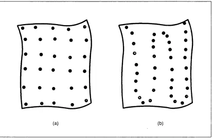
Figure 3.2 Typical data sets obtained from a hand-held sensor
using (a) pre-determ ined structure and (b)
free-stream ing m odes... 77
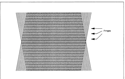
Figure 3.3 The patterns from tw o gratings at an angle to one
another form Moire fringes... 80
Figure 3.4 In Photogram m etry, the distance b, from the camera
to the object, and the distance d betw een the tw o camera
positions should be related by 0.3 < b/d < 1.0... 82
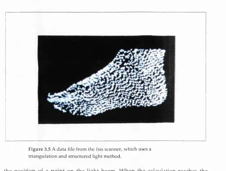
Figure 3.5 A data file from the Isis scanner, w hich uses a
triangulation and structured light m eth o d ... 84
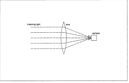
Figure 3.6 A silhouetting m ethod for capturing data from a leg
requires a lens to ensure that incom ing horizontal rays
are focussed at the cam era... 86
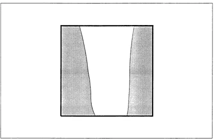
Figure 3.7 A typical image from a silhouetting m ethod for a leg. 87
Figure 3.8 In a silhouetting m ethod, tangent lines define a
Figure 3.9 A cross-section which cannot be picked up by a
silhouetting m ethod... 89
Figure 3.10 A silhouetting technique can be used to calculate 90
radial values for data at regular angular intervals...
C hapter 4 VIEW3D - A n Editor for T hree-D im ensional D ata Files
Figure 4.1 The m anner in which VIEW3D displays a data file
comprised of points on the edges of a bevelled cube. Note
that in this instance data points on the back of the cube
are obscured by points on the front... 99
Figure 4.2 The bevelled cube data file of the previous figure is
rotated about an axis perpendicular to the top left quadrant. The previously obscured data points are now
visible... 100
Figure 4.3 Visibilities are defined as the m axim um and
m inim um extents of the data file which are currently in
view ... 101 Figure 4.4 Alteration of the Visibilities affects the portion of the
data file currently in view. Each Visibility appears in two
screens and affects the view in the th ird ... 102
Figure 4.5 Examples of cross-sections of a data file from a foot. 103
Figure 4.6 M ovem ent of the three-dim ensional cursor in one
quadrant affects its position in one direction only in each
of the other quadrants. Here the m ovem ent is in the
u pper left q u ad ran t... 104
Figure 4.7 The Visibilities can be used to delete all points which
are not currently in view in all three q u ad ran ts... 105
C hapter 5 A Review of C om puter A ided G eom etric D esign and
Surface M odelling T echniques
Figure 5.1 The Bernstein polynomials of degree n = 4 ... 117
Figure 5.2 Examples of Bezier curves w ith their control
polygons... 118
Figure 5.3 A Bezier curve lies w ithin the convex hull of its control
Figure 5.4 The de Casteljau algorithm for n - 4... 120 Figure 5.5 Degree elevation of a cubic Bezier curve to a quartic
Bezier curve. The curve itself is unaltered... 123
Figure 5.6 In subdivision of a Bezier curve, the new control
points Ci are obtained from the de Casteljau algorithm
for the subdivision point... 124
Figure 5.7 A cubic H erm ite curve... 126
Figure 5.8 Examples of B-spline curves with their control points
indicated, and dem onstrating that the curves can be
open or closed... 129
Figure 5.9 Each portion of a B-spline curve lies w ithin the convex
hull of the relevant control points... 130
Figure 5.10 Local control of a B-spline curve m eans that if one
control point is repositioned only the 'nearby' curve
portions are affected... 131
Figure 5.11 The de Boor algorithm for calculation of a point on
a B-spline curve... 132
Figure 5.12 The knot insertion algorithm for a B-spline curve
uses the points generated by the first step of the de Boor
algorithm ... 133
Figure 5.13 The Bezier points for a B-spline curve... 134
Figure 5.14 A com m on estim ate for tangent direction at point /?,
is parallel to the line p, _ x p i + j ... 139
Figure 5.15 An interpolating smooth curve cannot possess the
variation dim inishing or convex hull property since
there m u st be a point p, and a plane through that point
which has all other points on one side of it, and cuts the
curve m ore often than it cuts the defining polygon 142
Figure 5.16 The 'H igh Resolution' choice in the UCL CASD
system uses Aitken's algorithm to determ ine
interm ediate values of radius. Two calculations are
show n... 144
Figure 5.17 For tw o H erm ite cubic curves to join sm oothly they
m ust have a common end point and parallel tangents at
Figure 5.18 For two Bezier curves to join sm oothly requires a
common end point and three collinear Bezier points. ... 146
Figure 5.19 B-spline curves can interpolate to points after
control points d{have been determ ined... 148
Figure 5.20 A Coons patch is a surface which interpolates its
four boundary curves... 153
Figure 5.21 A tensor product Bezier patch w ith its control points
and control polygon... 158
Figure 5.22 The deviation of the quadrilateral of control points
near a corner of a Bezier patch is proportional to the twist
at that corner... 162
Figure 5.23 A Hermite cubic tensor p roduct patch... 164
Figure 5.24 A Bezier triangle with its control points... 168
Figure 5.25 If the rows of control points across the join of two
adjacent Bezier patches are collinear, and in the same
ratio, then the join is tangent continuous... 176
Figure 5.26 Tensor product B-splines can interpolate points p ijf
b u t this requires determ ination of the control points d^ 177
Figure 5.27 The three possible rectangular situations - sheet,
cylinder and torus... 180
Figure 5.28 A foot shape cannot be m odelled over a plane
domain. A non-convex dom ain is required ... 181
Figure 5.29 A regular triangular m esh for Farin's m ethod 183
Figure 5.30 An arbitrary triangular m esh which requires Piper's
m ethod... 183 Figure 5.31 Examples of faces w ith other than four sides in
largely rectangular m eshes... 184
Figure 5.32 Examples of vertices of orders other than four in
largely rectangular m eshes... 186
Figure 5.33 An example of a large scale m anipulation. Here two
rows of interpolation points are m oved ... 188
Figure 5.34 An example of a local m anipulation for a tensor
product Bezier patch surface. Here one interpolation
point is m oved b u t the shaded area of the surface is
Figure 5.35 The central control point of a quartic Bezier patch
can be m oved without affecting the cross boundary
tangent continuity... 192
Figure 5.36 For tw o adjacent quartic Bezier patches the three
indicated control points can be adjusted by the same
am ount w ithout affecting the cross boundary tangent
continuity... 193
C hapter 6 A N ew Surface M odel for G eneral A pplication in
Prosthetics and Orthotics
Figure 6.1 Example meshes for parts of the hum an anatomy.
Vertices of orders other than 4 are indicated... 199
Figure 6.2 Example meshes for closed shapes - a sphere and an
ellipsoid... 199
Figure 6.3 A possible spiralling boundary betw een two adjacent
row s of patches in a non-rectangular situation... 200
Figure 6.4 The notation for param eters and Bezier points about
a vertex p... 203 Figure 6.5 The Bezier points for a system of quartic patches
around a vertex of order 5. The points undeterm ined by
position and tangent continuity conditions with other
patches are indicated by crosses... 204
Figure 6.6 A geometrical interpretation of (6.2) is that the
indicated vectors are equal... 205
Figure 6.7 If the vectors q( are of equal m agnitude and at equal
angles, then qt = X(^r, _ i + ^ +1) is anticipated for some X. 209
Figure 6.8 The effect of modifying the Bezier points about a
vertex of order 3 to satisfy the tangent conditions at the
vertex... 210
Figure 6.9 The effect of modifying the Bezier points about a
vertex of order 5 to satisfy the tangent conditions at the vertex... 211
Figure 6.10 Examples of the position of the tw ist Bezier points
Figure 6.11 The relabelling of the points required for tangent
estim ation at a point on the edge of the m esh... 223
Figure 6.12 The projection of the tangent / at p 0 in the direction
of p 3 is the fraction X of the vector p 3- p Q... 225
Figure 6.13 The projection of the vector bx - p 0 onto q3 should be
less than \ q 3 and more than rq3... 227
Figure 6.14 The direction of the tangent t at p 0 is in the direction
of the projection of p x into the tangent plane at p 0 231
Figure 6.15 The positions on the mesh of interm ediate points
which m ay be known, and which can be used for tangent
and twist estimation. Here m - 3 in the notation of this
section... 234
Figure 6.16 The notation for estim ating the tw ist at a vertex of
order four... 235 Figure 6.17 The notation for estim ating the tw ist at a vertex on
the edge of a m esh... 236
Figure 6.18 The relationship between tangent and tw ist vectors
and Bezier points for establishing explicit form ulae for
the points... 239
C hapter 7 A daption of the N ew Surface M odel to Particular
Situations and the Fitting of D ata to it
Figure 7.1 A rectangular mesh does not require sharp
right-angled corners because the shape of patches near
the corners can be adjusted... 249
Figure 7.2 A vertex of order 6 can be replaced by tw o vertices
of order 5. Similar procedures can be adopted for vertices
of higher o rd er... 250
Figure 7.3 Two adjacent exceptional vertices can be separated
by the introduction of a line of vertices betw een them. 251
Figure 7.4 A cap can be added to the end of a cylindrical mesh
to give a m esh suitable for a prosthetic socket including
Figure 7.5 A first possible m esh for a whole foot, corresponding
to 'sock7 shape. The rectangular regions and exceptional
vertices are indicated... 253
Figure 7.6 A second possible m esh for a whole foot,
corresponding to 'sole' and 'u p p e r' shape. The
rectangular regions and exceptional vertices are
indicated... 254
Figure 7.7 A m esh for the orthotic insole w ith rectangular
regions, exceptional vertices and size param eters
indicated... 255 Figure 7.8 An exam ple m esh for a below-knee prosthetic socket
constructed from data for the UCL CASD system 258
Figure 7.9 The m arker points added to a whole foot data file to
establish a mesh of the form of Figure 7.5... 259
Figure 7.10 The slicing procedure to establish a whole foot m odel
of the form of Figure 7.5... 261
Figure 7.11 A m esh for a whole foot constructed using the
dividing u p the data and averaging technique... 262
Figure 7.12 The m arker points added to an orthotic insole data
file to establish a m odel of the form of Figure 7.7, and
the subsequent orientation and slicing... 262
Figure 7.13 An exam ple m idfoot slice for curve fitting from an
orthotic insole data file... 265
Figure 7.14 The curve fitting technique for the slice of Figure
7.13... 266
Figure 7.15 A m esh for an orthotic insole constructed using
curve fitting techniques... 267
C hapter 8 Experim ental R esults from A pplication of the N ew
Surface M odel
Figure 8.1 The first stages of the iterative procedure to find the
Figure 8.2 A below-knee prosthetic socket represented by the
new surface model using data from every third slice and strip of a UCL CASD data file with interm ediate
information used in the estim ation of tangents and
tw ists... 276
Figure 8.3 A below-knee prosthetic socket represented by the
new surface model using data from every 4th slice and
strip of a UCL CASD data file w ith no interm ediate data
u sed ... 277
Figure 8.4 A whole foot m odel fitted by the dividing up and
averaging method. The toe region is clearly
unsatisfactory... 280
Figure 8.5 A slice of data from an orthotic insole data file
indicating one point which w as not well represented by
the m odel... 281
Figure 8.6 An orthotic insole m odel fitted by curve fitting
techniques... 284
Figure 8.7 The orthotic insole m odel of Figure 8.6 w ith prelim inary im plem entation of the plantar surface
eversion quantified by Foulston et al... 285
C hapter 9 MODEL - The Surface D isplay Softw are
Figure 9.1 A prosthetic socket m odel displayed in wire frame
m ode w ith all lines visible... 290
Figure 9.2 A prosthetic socket m odel displayed in wire frame
m ode w ith hidden lines rem oved... 291
Figure 9.3 The normal n to a sub-patch is the cross product of
its two diagonals r2- r 4 and r 1- r 3. The intensity w ith
which the sub-patch is shaded is determ ined by the
cosine of the angle betw een its norm al and the vector I
to the light source... 292
Figure 9.4 A prosthetic socket m odel displayed in a shaded solid
view w ith density = 4... 294
Figure 9.5 A prosthetic socket m odel displayed in a shaded solid
C h ap ter 10 C onclusions
Figure 10.1 The constituent parts of an integrated C A D /C A M
system for prosthetics and orthotics as in Figure 1.1, but
w ith the relevance of the w ork in the chapters of this
Table of Tables
C hapter 2 A First G eneration CAD System - The UCL C om puter
A ided Socket D esign System
T able 2.1 Com parisons betw een AP, ML and Circ dim ensions
in m illimetres taken from a patient's limb, and the
corresponding m easurem ents on a brim adjusted to fit
comfortably, m easured according to Figure 2.6... 51
C hapter 4 VIEW3D - A n Editor for T hree-D im ensional D ata Files
Table 4.1 The Form at for a VIEW3D Data File ... 97
C hapter 8 Experim ental R esults from A pplication of the N ew
Surface M odel
Table 8.1 The Point-Model Distances for a typical below-knee m easurem ent file from the UCL CASD system w hen
fitted to the new surface model. All distances are
truncated dow n to the nearest m m... 272
Table 8.2 The Point-Model Distances for a typical below-knee socket file from the UCL CASD system w hen fitted to
the new surface m odel... 273
Table 8.3 The m ean, standard deviation and m axim um
point-m odel distances of Tables 8.1 and 8.2... 275
Table 8.4 The Point-Model Distances for a whole foot m odel
fitted to the new surface model by data averaging (a)
w ithout m odifications and (b) w ith the heel and toe
region vertices m odified graphically. The results from
the heel and toe regions are included in the table 279
T able 8.5 The m ean, standard deviation and m axim um
point-m odel distances of Table 8.4... 279
Table 8.6 The Point-M odel distances for an orthotic insole file
fitted by curve fitting techniques... 282
Table 8.7 The m ean, standard deviation and average
Point-M odel distances for the orthotic insole model
C h ap ter 9 MODEL - The Surface D isplay Software
T able 9.1 The form at of one Bezier patch contained in a data file
Chapter 1
Introduction
Motivation
1.1
M otivation
Since the late 1950's, w hen computers first had a lim ited ability to display
graphical images, there has been a steady and consistent grow th in their
functionality and adaptability. C om puter graphics are now used in m any
diverse fields, such as C artography, C hart and G raph Plotting for Business
Planning, A nim ation, Simulation, Process Control and Planning, Office
A utom ation, Desk-Top Publishing and Creative Art. M any of these applications
rely on the old adage that 'a picture is w orth a thousand w ords', and com puters
can be good at translating large quantities of num erical or quantifiable facts into
pictoral inform ation. Because of this, it was soon appreciated that com puters could be particularly useful as an aid to the process of design, and this application
has grow n into a field of its own, C om puter Aided Design, or CAD for short.
Frequently, CAD is combined with C om puter A ided M anufacture (CAM) by,
say, use of a com puter-controlled milling m achine to produce the object designed. This gives rise to the term C A D /C A M for an integrated system.
The first im plem entations of CAD were concerned w ith the application of
com puters to the design and m anufacture of engineering components. Because of the expense of com puter graphics equipm ent at the time, CAD was mainly
advanced by its adoption into major industries such as the aircraft and
autom otive sectors. Here the necessity to design intricately-shaped and
aesthetically pleasing surfaces acted as a catalyst to developm ent, inspiring work
by Coons and Bezier [COONS 67, BEZIER 66, BEZIER 67], and culm inating in
sophisticated surface m odelling techniques, and ultim ately, software packages such as Bezier's U nisurf package [BEZIER 86], and others [IMSL, SI]. In this
context, surface m odelling refers to the use of a m athem atical technique to define
precisely and unam biguously the shape and other characteristics, such as
sm oothness, of a surface. An influential discussion of the com putational
m ethods was given by Faux and Pratt, w ith thorough up-to-date reviews and
presentations of general engineering-inspired CAD system s by Besant and Lui
and Davies et al [FAUX & PRATT 79, BESANT & LUI 86, DAVIES et al 91]. Many m odern CAD system s dispense completely w ith the need for the draw ing by
hand of conceptual designs since they include the ability to plot out engineering
There are m any considerations which affect the design process, and various
forms of analysis can be undertaken to ensure design criteria are met. It has
therefore been natural for CAD systems to be developed w ith analytical
functionality, and now m ost commercial CAD packages, for example A utoCad and I-DEAS, provide such analytical ability to enhance their design features
[AUTOCAD, IDEAS]. Meanwhile, the price of the com puter hardw are m easured
against its perm ofm ance has continually reduced so that today there are many
more applications of CAD, both in engineering and in other areas such as
geology, shoe pattern design for standard lasts, the clothing industry and
medical and dental applications [BARSKY & GREENBERG 80, MCCARTHY &
HANDSCOMB 89, FLUTTER 83, MCCARTNEY & HINDS 89, VERGEST et
al 87, WALKER 88, BRAMWELL et al 90].
Through the use of CAD systems, the com puter has become a very useful designing tool. It is however, only a tool, and will not replace the designer
because its functionality is restricted, and its knowledge lim ited to that which is explicitly built into the software used. Besant and Lui [BESANT & LUI 86] have suggested that in a CAD environm ent, the com puter has three main
functions
(1) To serve as an extension to the m em ory of the designer;
(2) To enhance the analytical and logical pow er of the designer;
(3) To relieve the designer from routine repetitous tasks.
Moreover, they suggest that the designer has three com plem entary
tasks:-(1) Control of the design process in inform ation distribution;
(2) Application of creativity, ingenuity, and experience;
(3) Organisation of design information.
In the 1980's, several centres including the Bioengineering Centre at UCL
decided the time was ripe to apply CAD techniques to prosthetics and orthotics. Lord and Jones in their discussion of issues in CAD for prosthetics and orthotics
[LORD & JONES 88] recognised that an integrated C A D /C A M process w ould
stages:-(a) M easurem ent w hereby body shape and other pertinent information
are converted to digital data;
(b) Shape generation by integration of individual m easurem ents, a
knowledge base and interactive adjustm ent via the com puter; (c) M anufacture of this physical com ponent via a com puter-controlled
machine.
At UCL, the design and m anufacture of prosthetic sockets for below-knee
lower-limb am putees w as chosen as the first project for the introduction of CAD,
and it was broken dow n into stages following the pattern outlined by Lord and Jones. The crucial part of the system was regarded as the shape generation, stage
(b), which involved the distortion of the original body shape to yield pressure
in certain areas of the socket and relief in others, a process know n as
'rectification'. Rectification tem plates are determ ined by a series of
m easurem ents m ade on the corresponding craft-based procedure. Stages (b)
shape generation and (c) m anufacture could be repeated for an iterative design of a final socket, if required. The result w as a software package, C om puter Aided
Socket Design (CASD), for below-knee socket design, commercially available since 1989. At this time, the author joined the Bioengineering Centre. He was
p art of a small team responsible for the philosophy behind a CAD system for
the design of above-knee sockets, and had sole responsibility for the
developm ent of the software for this second CASD m odule, commercially
available since 1990, and which has been docum ented as C hapter 2 of this thesis.
O ther packages for the design of below-knee lower-limb prosthetic sockets also
became available during the 1980's [SAUNDERS et al 85, HARLAN &
BOONE 89].
The advantages offered by CAD system s to prosthetics and orthotics are several.
One advantage is that by using com puter graphics, the result of the design can
be visualised before it is actually m anufactured. This can m ean that certain
features in the design become m odified before the item is produced, possibly
reducing the am ount of m odification required after m anufacture. Other
analytical techniques, such as volum e or mass analysis, can be carried out by
the com puter w ith sim ilar benefits. A further advantage is that the com puter
Therefore an exact replica can be easily produced for repeat orders. This is a
feature which is commonly unavailable in prosthetics and orthotics since each
item requires individual input from a skilled person whose decisions and actions
are by their nature not recordable in precise num erical detail. Time is often a
consideration in the design of a prosthetic or orthotic component. Often, CAD
system s increase the time efficiency of the overall process by enabling the
designer to concentrate on those stages where his experience and expertise are
m ost required. Time and efficiency im provem ents are anticipated w ithin a
prosthetic and orthotic environm ent where a good CAD system is employed. Because the design of any custom-m ade item is an iterative process, especially
if the criteria affecting the design alter with time, then since all the previous
designs for a certain patient can be recorded, the iterative process can be easily
m onitored to the benefit of the final design. This is perhaps the m ost significant
advantage of a CAD system in this setting, but each of these advantages has
been dem onstrated with the CASD system.
The CASD package developed at UCL and several other packages previously
m entioned produce socket shapes which are defined by the positions of a
num ber of discrete points on the surface shape. Such a m ethod of shape definition implies that the precise shape of the socket between the know n
discrete points is not determ ined, and, in practice, it is the m anufacturing
technique which passively ensures the sm oothness of the com ponent to a large
degree. The surface m odelling work in the m anufacturing engineering sectors
by Coons, Bezier, Faux and Pratt and others m entioned above and sum m arised
by Barnhill and Bohm et al [BARNHILL 83, BOHM et al 84], provides surfaces
whose shape is entirely defined, and this fact implies that smooth surfaces can
be guaranteed. O ther advantages of surface m odelling are that storage efficiency
may be enhanced by requiring less inform ation, and controlled adjustm ents of
the surface are more easily quantified. One m otivation for the current project
was to add these techniques to the CASD package to determ ine the advantages
which they offer. To date the possibility of advantage has been suggested
[REYNOLDS 88, LORD & JONES 88], b u t not im plem ented or evaluated.
Some surface m odelling techniques, for exam ple B-splines, bi-beta functions and
VERGEEST et al 87, SAUNDERS et al 85], b u t the im plem entation of these
schemes requires a rectilinear grid of points for the model, and this has restricted their application to cases where a distorted sheet w ith a rectangular mesh can
be w rapped over the surface. This is applicable in the approxim ately cylindrical
case of prosthetic socket design, but for other cases such as orthopaedic footwear
or the orthotic insole, the situation is inappropriate, leading, for example, to
consequent loss in sm oothness of the final design. M oreover, CAD techniques available to date for prosthetic and orthotic applications are each dedicated to
one particular situation. A second motivation was therefore to further develop
the surface m odelling techniques used in engineering applications to generate
a CAD philosophy and system which w ould be applicable in m any prosthetic
and orthotic instances. The author was the research assistant from 1987 to 1989
for a SERC fu nded project at University College London looking into surface representation possibilities for orthopaedic footwear, and application of the
system will be dem onstrated in work arising from that project.
The UCL CASD system is regarded as a First G eneration system because of the
limitations suggested in the previous two paragraphs - first, the system at no
stage has a know ledge of the entire surface shape which it designs, and second, because of its reliance upon the structure of the data being in a rectangular grid,
the philosophy cannot readily be extended to a general system for prosthetics
and orthotics. The aim of the current work is to lay the foundations for a Second
Generation CAD system for prosthetics and orthotics by the inclusion of surface
m odelling, so th at the final surface could be completely controlled, and that the
system should be readily adaptable for m any situations in these fields. In the
m anner of Lord and Jones, the Second G eneration system w ould have
constituent stages as show n in Figure
1.1:-(i) M easurem ent or capture of the body shape and in p u t of other pertinent
inform ation;
(ii) Exam ination and checking of the m easurem ent data;
(iii) C onstruction of a surface model for the particular situation under
consideration;
(iv) A daption of the m easurem ent data to become the data required by the
M easu rem en t of patient
O u tp u t of d a ta an d
m a n u factu re of c o m p o n e n t
A c ce p ta n c e of final d e sig n C onstruction
or selection of su rface m odel
Exam ination a n d editing of m e a su re m e n t file
Adaption of m e a su re m e n t to su rfa c e m odel
Iterative desig n S h a p e G en eratio n
Figure 1.1 The constituent parts of an integrated CAD/CAM
system for prosthetics and orthotics.
(v) Shape generation by integration of individual m easurem ent, a
know ledge base, the surface model and interactive graphical
adjustment;
(vi) O utput of the shape inform ation for m anufacture of the physical
com ponent under com puter control;
(vii) Iterative design and m anufacture of an im proved com ponent based
upon clinical assessment, including patient comfort and other factors.
Each of these stages is now briefly discussed w ith regard to the envisaged system.
M easurem ent Techniques for m easurem ent, or 'D ata C apture', are not central
to this thesis. Each technique involves significant developm ent and experience
of its own. However, it is im portant to understand the structure of the data which
the techniques yield. In particular, the system m ust be able to handle the data
from several m easurem ent techniques and it w ould be useful to know if the data
Exam ination of m easurem ent data Often m easurem ent techniques will have
their ow n facilities for checking the m easurem ent data. H ow ever, som e m ay not
have, and the system should incorporate a software tool w hich allows visual
presentation of the m easured data together with the ability to edit the data,
thereby rem oving erroneous points, for example.
Surface Model Construction At som e stage, the surface m odel appropriate to
any situation will need to be constructed. It is likely that the end user, however,
will not w an t to be involved w ith the technicalities of surface m odelling, and so the system will contain a library of m odels for the cases to which the system will
be applied, and the user will then choose the model appropriate to his situation.
A daption of M easurem ent Data After choice of the relevant surface model, the
system will ad ap t the m easurem ent data so that it is in the correct form for the
surface model.
Shape Generation The system will generate an initial shape by replication of the
m easurem ent shape, and the system will give a visual presentation of this shape. The ad opted shape will be form ed by the integration of the m easurem ent shape
and its graphical portrayal, a know ledge base which contains an understanding of how the shape is affected in the particular situation u nder consideration, and
interactive adjustm ent in response to both the image presented and patient or
o ther com m ents on previous designs.
O u tp u t for M anufacture Although the m anufacture of the com ponent is not part
of the current w ork, the system m ust produce shape inform ation w hich is readily
adaptable to various com puter controlled m anufacture processes. W ith surface
m odelling techniques it will be possible to produce data in the form of positional inform ation on the surface at any required density and in any required pattern.
Iterative Design Design of orthotic and prosthetic com ponents is rarely perfect
at its first attem pt. Often, comm ents upon and experience of previous designs
Inform ation from previous designs should be stored by the system and
introduced at the stage of shape generation, w ith the prosthetist or orthotist
controlling the reaction to this information.
There is no reason w hy several of the stages should not be remote from the
others. This w ould open up the possibility of having one central design and
m anufacture site serving either m any outlying m easurem ent sites to which the
m anufactured items w ould be returned, or one mobile m easurem ent facility
which w ould tour the outlying product destinations. If the elements of the
process are expensive, this could ensure a significant increase in cost-efficiency.
A general CAD system for prosthetics and orthotics is not envisaged to replace the trained prosthetist or orthotist, but rather to be an aid to him in consistency
and efficiency. In the m anner of Besant and Lui, the function of the CAD system
is envisaged to
be:-(i) To serve as an extension to the m em ory of the user, especially as an aid
to the iterative process of design;
(ii) To enhance the analytical and deductive pow er of the user;
(iii) To carry out standard rectification, modification or other design
procedures for the user, i.e. to act as an expert system;
(iv) To allow visualisation of the designed item before m anufacture.
The responsibilities of the trained prosthetist or orthotist will
be:-(i) Overall control of the design process;
(ii) Interpretation of the clinical requirem ents into quantitative inputs for
the system;
(iii) Interpretation and action upon the results of the analysis and
visualisation;
(iv) O rganisation of the design inform ation, including information such as
1.2
Contributions of the Current Study
In this section, the contributions of the current project are sum m arised.
(a) The extension of the UCL C om puter A ided Socket Design (CASD)
system to above-knee prostheses is described and documented. The
presentation given here is com plem entary to the earlier discussion by
Reynolds and Reynolds and Lord of the UCL CASD system for
below -knee prostheses [REYNOLDS 88, REYNOLDS & LORD ip];
(b) A softw are program for the evaluation and examination of three
dim ensional data files is presented. The program has the useful
features of allow ing the graphical spatial editing of points in the file an d the addition of m arker points to the file;
(c) A review of data capture techniques used in prosthetics and orthotics
is presented w ith the form of the data file produced of particular interest;
(d) A review of curve and surface m odelling techniques is presented with
particular em phasis on their use to interpolate a num ber of data points;
(e) A new surface m odel which sm oothly interpolates a num ber of given
(x,y,z) points is developed. Explicit conditions and procedures for the
construction of the surface are given together with m ethods for
m odification of the model;
(f) M ethods are presented for adapting the new surface model to
particular situations and fitting data files to the m odel with specific
exam ples given for the prosthetic socket, the whole foot and the
(g) Surface m odelling is introduced to the UCL CASD system to
determ ine and attem pt to quantify the advantages which surface
m odelling offers over a system which contains a know ledge of the
surface only at discrete intervals;
(h) Initial experimental results are presented to determ ine how well the
new surface model fits data sets from the whole foot and orthotic insole
applications;
(i) A surface visualisation software program is presented, which includes
the ability to display objects comprised of the new surface m odel in
both wire frame and shaded solid modes.
1.3
Structure of the Current Thesis
In this chapter, the term C om puter Aided Design has been introduced together
w ith its brief history, its common uses and the potential benefits it offers to prosthetics and orthotics. In C hapter 2, the system developed at UCL to autom ate
the design of above-knee prosthetic sockets is described. This system itself is not
the major contribution of the thesis, but rather, as previously outlined, is
regarded as a springboard for the developm ent of a m ore general CAD system for prosthetic and orthotic application to which the rem ainder of the thesis is
dedicated.
Applications of a CAD system in prosthetics and orthotics involve the capture
of an existing shape, often p art of the hum an anatomy. Therefore, C hapter 3
presents a review of data capture techniques, including tactile, visual and other
m ethods, and suggests the structure and form of the data which should be
expected by a CAD system. After data have been captured from w hatever device
is appropriate, there is often a need to examine and edit the data. Moreover, it was found in the im plem entation of the developed surface m odel that m arker
points to highlight features such as bony prom inences were frequently useful.
C hapter 4 presents a software tool which enables graphical exam ination, editing
For the system to produce a smooth surface, an understanding of the
m athem atical definition of the surface designed will be required. C hapter 5
presents a review of curve and surface m odelling techniques, w ith a particualar
em phasis on how these techniques are used to construct surfaces which
interpolate a num ber of given data points. A conclusion from C hapter 5 is that
further developm ent is required to derive a smooth surface m odel which will cater for m any of the shapes commonly encountered in prosthetics and orthotics.
This developm ent is the subject of C hapter 6, the result being a generally
applicable surface model. Even after the addition of m arker points and the
exam ination of the data file, the data are not in the right form for the surface
model. C hapter 7 presents a m ethod for adapting the surface m odel to particular
situations, and gives exam ples of the use of differing techniques for the fitting
of data sets to the new surface model in these situations. Examples are given
from prosthetics and orthotics. As yet, the advantages to prosthetics and orthotics of a smooth surface model over a technique which involves only discrete positional inform ation about the surface are suggested but unproven.
In C hapter 8, tests of these advantages are undertaken by application of the new
surface m odel to the UCL CASD system. O ther results are presented to determ ine the reliability of the fitting techniques of C hapter 7, and how well the
surface model represents data in sample prosthetic and orthotic situations. In
o rder to gain a good understanding of the shape of the surface before it is
com m itted to a m anufacturing process, it is necessary to visualise the surface,
and C hapter 9 presents the surface visualisation tool developed du rin g this
project.
In C hapter 10 the m ain findings of the current project are sum m arised and
Chapter 2
A First Generation CAD System
-The UCL Computer Aided Socket D esign System
2.1
Introduction
2.2
Conventional above-knee socket Design
2.3
Philosophy of the system
2.4
Brim shapes and sizes
2.5
Capture and storage of residual limb shape
2.6
Blending brim and residual limb shapes
2.7
Shape visualisation
2.8
Modification of the socket shape
2.9
Shape carving and socket production
2.10
The user interface
2.1
Introduction
The total low er limb am putee population in England in a recent survey was
51,130, or, 0.1% of the general population [DHSS 86a, DHSS 86b]. Following
w ork to im prove consistency an d productivity in the m anufacture of the
prosthetic sockets required by this population, the Bioengineering Centre of the
Mechanical Engineering D epartm ent, University College London developed its
ow n CAD system for custom -designing below-knee prosthetic sockets. The
system has been extensively docum ented elsewhere [REYNOLDS 88, DEWAR
et al 85, DEWAR & REYNOLDS 86].
After the success of the below-knee prosthetic socket CAD system, currently
being sold in the UK, the USA and elsewhere, the Bioengineering Centre
developed its ow n CAD system for custom-designing above-knee prosthetic sockets. The author w as involved in this project from the early stages and was
solely responsible for the brim shape and size, blending, rectification and user
interface software, and contributed to the overall system design as p art of the small research team. The CAD system is nam ed C om puter A ided Socket Design
(CASD).
The conventional above-knee prosthetic socket design technique is first
described in this chapter because the chosen philosophy for the UCL CASD
system is to reproduce as closely as possible the design m ethod used
conventionally. Some advantages of such a philosophy are that each stage of
CASD can be com pared w ith its respective stage in conventional design, and
also that such a CAD system will be more easily accepted into the prosthetics
field by operators w ho are naturally wary of computers. The reasons behind the
choice of this philosophy are described later in the chapter.
For the purposes of designing a CAD system, the process m ay be separated into
three stages:- (i) the capture and storage of the shape of the patient's residual limb, (ii) the design of a good socket shape, and (iii) the autom ated socket
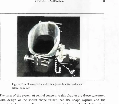
F igure 2.1 A H osm er brim w hich is adjustable at its m edial an d lateral extrem es.
The parts of the system of central concern to this chapter are those concerned
with design of the socket shape rather than the shape capture and the
m anufacturing process. The shape capturing technique used in the UCL system is described concisely here, but it is the same as that used in the below-knee
prosthetic socket system, which is more completely docum ented by Reynolds
[REYNOLDS 88]. Many commercially available com puter-controlled machines
are capable of producing a physical positive shape; m ore efficient socket
manufacture may be possible with purpose-built machinery. The m anufacturing
system used at the Bioengineering Centre is briefly described.
2.2
Conventional Above-Knee Prosthetic Socket Design
A prosthetic socket is the interface between an am putee and his artificial limb.
His comfort while wearing this component is a major factor in determ ining his
Figure 2.2 A n u n ad ju stab le Blatchford 'E u ro p e a n ' brim .
Socket design is specific to the user and it m ust achieve a close fit while providing
stable support of the residual limb through those areas best suited to tolerate loading. The socket should be comfortable and stable and allow dynamic
m ovem ent such as walking. The shape best able to satisfy these conditions is not a simple copy of the residual limb as this, for example, w ould cause loading
in the wrong areas such as the distal end of the limb. Rather, distortions are
incorporated into the limb contours which judiciously encourage loading in
certain areas and relief in others.
The design and m anufacture of an above-knee prosthetic socket can be divided
into five stages:- brim fitting, casting of the residual limb, m anufacture of a plaster positive from this cast, rectification and final m anufacture of the socket.
The first stage of the process to design the correct shape for an above-knee
prosthetic socket is brim-fitting. This follows a 'quadrilateral' socket philosophy
suggested by Foort [FOORT 63]. Typically a prosthetist will have one or more
sets of brim s which are basically scaled versions of each other to accommodate
J !
i I
i
I
j
Figure 2 3 Measuring the anteroposterior (AP) dimension.
brims and the Blatchford European brims, Figures 2.1 and 2.2. The H osm er brims typically come in sizes 5 ^ ", 5^", 6 ^ ", 6 ^ " and 7^", and are adjustable at the
m edial and lateral extremes. The Blatchford European brim s typically come in sizes 40 cm, 42 cm, 44 cm, 46 cm, 48 cm, 50 cm, and 52 cm, and are not adjustable.
The shape of the brim will determine the shape of the proxim al portion of the socket.
The prosthetist m easures some key dimensions on the residual limb,
namely:-(i) the antero-posterior dimension from the top of the ad ductor longus tendon
to the ischial tuberoscity (AP dimension), Figure 2.3, (ii) the medio-lateral
dim ension from the head of the trochanter to the ischial tuberoscity (ML
dimension), Figure 2.4, and (iii) the circumference at the perineum , Figure 2.5.
Often, a prosthetist will reduce the circumference dim ension by approxim ately
6% so that the final socket will fit snugly in this area. These dim ensions indicate
to the prosthetist which brim will fit the patient.
For a quadrilateral adjustable brim, such as the H osm er brim , the ML dim ension
Figure 2.4 Measuring the medio-lateral (ML) dimension.
Posterior
/ C ircum ference
AP
A nterior
Figure 2.6 The correspondence between the dimensions and the
brim shape.
and lateral openings are then adjusted so that the AP and Circumference
dim ensions correspond to m easurem ents on the brim , Figure 2.6. The brim is m ounted on a jig in which the patient stands, and any necessary fine adjustm ents
are m ade so that the patient feels comfortable. For a non-adjustable brim , such
as Blatchford's European brim, the circumference dim ension determ ines which
brim is chosen, and the brim which has circumference value nearest to the value
m easured on the patient is fitted to his leg.
Prior to casting, the residual limb is covered with a thin nylon sock to enable the
cast to be rem oved easily, and the limb is put into approxim ately 10° flexion
since this is roughly the position the limb w ould assum e w ithout loading. While
the patient is standing in the brim, the prosthetist takes a cast of that portion of
the residual limb which protrudes. This is done by w rapping plaster of paris
bandages over the limb and the sock while the brim is weight-bearing, and
extending the bandages u p to cover the bottom edge of the brim. W hen fully
A positive m odel is then prepared by pouring plaster mix into the w rap cast. It
is usually at this stage that an axis is established within the prosthetic shape.
Before filling with the plaster mix, a m andrel is positioned w ithin the w rap cast.
The orientation of the prosthetic shape relative to the m andrel is m aintained th ro u g h o u t rectification and socket fabrication and eventually fixes the 'bench'
alignm ent which determ ines the initial set-up of the socket on the artificial limb.
The w rap cast is cut aw ay to leave a plaster positive.
At this stage the socket is ready for rectification, a sculpting process in which
m aterial is rem oved in those areas where pressure is to be applied and added
w here relief is necessary. Often a depression is introduced at the proximal end
of the positive to lock the trochanter into position and prevent the final socket
rotating. O ther rectifications m ay include relief to prevent irritation caused by rubbing u nder the ram us.
Final m anufacture of the hard shell socket is commonly achieved in England by
drapeform ingby hand or w ith a semi-automatic RAPIDFORM machine. A nylon sock is p u t on the rectified plaster positive before a pre-heated polypropylene sheet is draw n dow n to form the socket shell. Vacuum is applied to encourage
conform ity between all surfaces. Once the polypropylene has cooled, the plaster
positive is broken out and residual material is trim m ed aw ay to complete socket
fabrication.
The fit of the socket will be assessed over a period of time as the patient wears
it. If there are m inor changes which w ould im prove the fit, extra p adding can
be ad d ed internally to the socket, or the rim can be trim m ed. How ever, if m ore
fundam ental alterations are required, the entire procedure m ust be repeated
since the plaster positive w as destroyed on breaking it out of the polypropylene
2.3
Philosophy of the System
Prior to the developm ent of the UCL CASD system for above-knee am putees,
there was no commercially available system regularly used in the fitting of such
patients. Therefore it is informative to look at the philosophies em ployed in
CASD system s for below-knee amputees.
Saunders and Foort of UBC, Vancouver had produced a com puter based system
for designing lower-limb sockets [SAUNDERS et al 85] before the UCL system was developed. The UBC system uses a limited num ber of limb m easurem ents
to scale a 'reference' socket shape to provide a reasonable socket design.
Thereafter, interactive on-screen m odifications are m ade to the shape to produce
the final fit. Sets of m easurements are taken w ith calipers and tape-m easure. A ntero-posterior and medio-lateral m easurem ents at the knee are used by the
software to scale the proximal part of the reference socket in cross-section and
length before antero-posterior and circumferential m easurem ents distal of the knee joint, at one inch intervals, are used to 'tap e r' the scaled reference shape.
Final modifications, where patches of m aterial are added or rem oved to im prove
fit, are m ade via an interactive graphics display which can produce wire frame m odels and plots of cross-sections.
In num erical terms, the 'scaling' and 'tapering7 operations are transform ations
of the reference shape which is stored as a set of cylindrical polar coordinates.
The patches are added to the transform ed shape by superim posing
displacem ents onto the coordinate data. These patches are generated using
bi-beta functions with zero value and derivative at the boundaries. The
philosophy of this system is that all limbs have broadly similar structure, and
are therefore accomm odated by sockets of broadly similar shape and that the full 'fam ily' of these shapes m ay be produced by varying a few geometric
param eters on a 'reference' shape.
An alternative philosophy for below-knee CASD is to accept conventional
m easurem ent of the full limb surface is necessary. Rectifications m ust be
correctly positioned according to each am putee's anatom y or, if legitimate, in
standardised locations relative to a num ber of reference points.
This latter philosophy was favoured by UCL since early versions of the UBC
software were not flexible enough to produce sockets for a w ide range of limb
types w ithout a large am ount of interactive modification, and further scaling
param eters were desired to extend the 'fam ily' of available socket shapes.
Therefore, for the UCL system, reproduction of conventional techniques was
considered m ore likely to produce a successful fit since the underlying anatomical shape is present in each socket and the rectifications are relatively
small distortions of this shape.
A CASD m ethod for the design of above-knee prosthetic sockets based on a
'fam ily' of shapes has been published [KROUSKOP et al 87, KROUSKOP et al
89]. However, the philosophy of this system is that used by Saunders et al for the below -knee socket design, and is open to the same limitations. A similar
philosophy is suggested by Young [YOUNG 84], although that project was based on tw o unreliable m easurem ents, and the report does not detail any patient
fittings.
As w ith the below-knee CASD system, UCL favoured the philosophy of
mim icking conventional techniques. This involves fitting a brim shape to the
patient before casting and rectification, and is described more fully in the
previous section. It w as envisaged that the shape capture, small scale
m odifications and socket m anufacture w ould be the same as those em ployed in
the below-knee system. In some sense, this philosophy is a cross betw een the
tw o which em erged for below-knee socket design: the proxim al end of the socket
is originally one of a 'fam ily' of brim shapes, and the distal end is based on the
patient's individual m easurem ents. As m entioned in the previous section, this
philosophy has advantageous side-effects in that each stage in the process can
be com pared w ith the respective conventional stage, and the system is more