Themed Section: Science and Technology
A Novel Method for Automatic Electricity Metering and Theft
Detection through Single Phase System
Prof. Nileshkumar Jayawant Kumbhar, Madhuri Shivaling Patil, Akash Vitthal Redekar, Sagar Banda Magadum, Arjun Ananda Chopade, Swapnil Suresh Tavandkar
Department of Electrical Engineering, Ashokrao mane group of institutions, Kolhapur, India
ABSTRACT
In Present system there is less automation is available for taking electricity reading. Since reading is taken by employee who work for electricity board. This system has drawbacks like observational error, delay in billing process. To overcome this problem new approach is carried out in proposed system is called as automatic meter reading. In this method reading is taken via micro-controller and data are transferred with the help of power line modem.
Keywords: ISIA, LCD, MCU, PLC, RXD, TXD.
I.
INTRODUCTION
Power is the soul of world which is related to the electricity and “electricity” is the word which now rules the world. So, proper utilization of this commodity is of immense important to us. Hence, it is necessary to measure power consumption. Normally, large scale industries consist of various departments like production, storage, package, administration, transportation situated away from each other. For such industries, it is necessary to maintain record of daily power consumed by every department to keep check on excess power consumed .A power line carrier (PLC) communication system operating on a conventional three wire Hot (H), Neutral (N) and Ground (G) wires) power line uses more than one of the several RF transmission lines that are defined by the three wire power line to improve communication between units of the PLC system. According to a first embodiment a PLC system transmitter sends out of phase RF signals across the H and G wires and across the N and G power wires to the PLC system receiver, which receives and combines both of the out of phase transmissions, and so even if one of these paths is severely attenuated, the other path can deliver a
sufficiently strong RF signal to the receiver for effective communications. According to another embodiment three different pairs of the H, N and G wires of the power line are selected in sequence for transmission of the PLC system RF and the pair that results in the best communication between a system transmitter and receiver is used for continuing communication. Also includes power theft detection system which is the main cause of loss of Supply Company.
II.
LITERATURE SURVEY
By researches conclusion is that there is need of avoiding manual readings taken by employee. In this paper an survey is done for modifying a proposed system that will illuminates the problems of existing system.
A.PLC modem
which is capable of providing 9600 baud rate low rate bi-directional data communication. Due to its small size it can be integrated into and become part of the user’s power line data communication
Figure 1. PLC modem
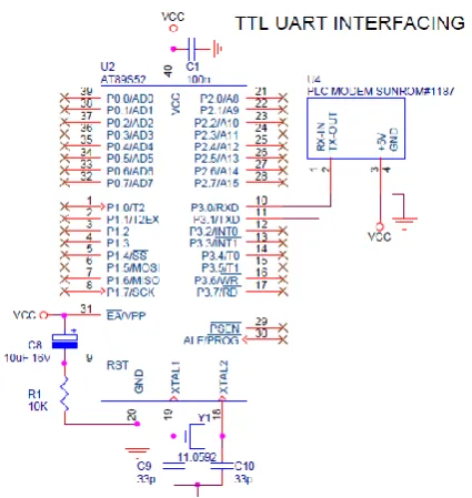
PLC interfacing with microcontroller:
Interface the module with directly microcontroller pins since the level of module is at 5 V level. 8051 microcontroller is configured to communicate at 9600 baud rate. The TXD pins of MCU will go to RX-IN pin of PLC modem. The RXD pin of MCU will go to TX-OUT pin of PLC modem ground and +5 power supply between PLC modem and MCU should be connected.
Figure 2. Interfacing with microcontroller B Opto –coupler
Gallium Arsenide Diode Infrared Source Optically Coupled to a Silicon npn Phototransistor.
High Direct-Current Transfer Ratio
Base Lead Provided for Conventional Transistor Biasing
High-Voltage Electrical Isolation-1.5-kV, or 3.55-kV Rating
Plastic Dual-In-Line Package
High-Speed Switching:
tr = 5 μs, tf = 5 μs Typical
Designed to be Interchangeable with General Instruments MCT2 and MCT2E
Figure 3. Opto-coupler C. LCD
Alphanumeric displays are used in a wide range of applications, including palmtop computers, word processors, photocopiers, point of sale terminals, medical instruments, cellular phones, etc. The 16 x 2 intelligent alphanumeric dot matrix display is capable of displaying 224 different characters and symbols. A full list Of the characters and symbols is printed on pages 7/8 (note these symbols can vary between brand of LCD used). This booklet provides all the technical specifications for connecting the unit, which requires a single power supply (+5V).
III.
BLOCK DIAGRAM
The first customer section consists of digital energy meter and control system. The output of the processor IC is a digital pulse, which depends upon the load used. These digital pulses are given as the input to the second section through the Opto-coupler. Hence the energy consumed by the consumer is calculated digitally. The control system in customer section is the heart of the system which consists of the micro controller.
For every 3200 pulse the micro controller receives it increases the number of units consumed by the consumer by 1, which is stored in the EEPROM. This is then displayed in LCD. The vendor section consists of the MODEM which is a transceiver i.e. it can receive as well as transmit data. The modem receives the input from the microcontroller and transmits it to the EB side. These are received by the modem placed in the EB side and sent to the PC. The tariffs are calculated using VB software by the PC and sent to the micro controller through the same pair of MODEM. Hence the number of units consumed and the amount is displayed in the LCD.
IV.
ELECTRICAL THEFT
Theft detection:
Theft of electricity is the criminal practice of stealing electrical power. It is a crime and is punishable by fines and/or incarceration.
Theft is done by following ways-
Direct hooking from line is the most used method for theft of power. 80% of total power theft all over the world is done by direct tapping from line. The consumer taps into a direct power line from a point ahead of the energy meter. This energy source therefore is unmeasured in its consumption and procured with or without switches.
By passing energy meter method the input terminal and output terminal of the energy meter has been
shorten by a wire. So energy cannot be registered in the energy meter.
Sometimes skilled individuals inject foreign elements such as transistors, resistors or IC chips into the electrical meter which causes a lower consumption of electricity.
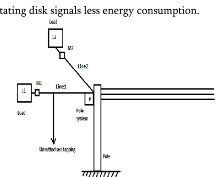
By tampering the meter. This type of tampering is done to electro-mechanical meters with a rotating element. Foreign material is placed inside the meter to obstruct the free movement of the disc. A slower rotating disk signals less energy consumption.
Figure 5. Conceptual diagram
Power Theft Detection-
L1, L2 Single phase loads M1, M2 Digital energy meters
P Pole based system (installed on a distribution pole)
Consider a distribution system shown in conceptual diagram. Two single phase loads L1 and L2 are supplied from two different phases. M1 and M2 are the energy meters that measure power consumed by these loads over a period. Pole based system (P) have been installed to detect power theft.
V.
PROPOSED WORK
Figure 6. Hardware setup Unit of main meter:
Figure 7. Main Meter Unit of customer S1:
Figure 8. Customer 1 Meter Unit of customer S2:
Figure 9. Customer 2 meter
VI.
SPECIFICATION OF HARDWARE MODEL
Sr. No.
Component Rating
1 PLC modem Serial data at 9600 bps, power from 5Vdc 2 Microcontroller AT89S52, 5 volt dc
supply
3 Opto-coupler Electrical isolation 1.5kv-3.55kv rating 4 LCD LED008 16*2
alphanumeric display 5 Energy Meter Single Phase 230 volt,
50 hz, 5-30amp 6 Arduino Arduino Uno,
Operating on 5 volt dc 7 Bulb 40 watt, 60 watt,
200watt 8 Connecting
wires
1.5 sq.mm
VII.
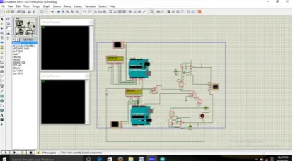
SIMULATION AND RESULT
Figure 10. Proteus simulation
VIII.
CONCLUSION
Reduction in manual meter reading costs.
Reduction in late and estimated billing costs.
Improved meter accuracy & Reduced meter maintenance expenses.
Reduction in Revenue Protection losses.
Ability to detect tamper events and outage occurrences.
IX.
ACKNOWLEDGMENT
We are thankful to HOD- Electrical Department, Dean Administration and Director for their constant encouragement to take research oriented work. We are also thankful to management of Ashokrao Mane Group Of Institutions, Vathar, affiliated to DBATU-lonare.
X.
REFERENCES
[1]. Nikovski,D, Wang,Z,,Esenther "Smart Meter Data Analysis Of Power Theft Detection," Technical Report-TR2013-065, July 2013.
[2]. Depru, S, "Modeling, Detection And Prevention Of Electricity Theft For Inhanced Performance And Security Of Power Theft", Doctoral thesis,the University of Toledeo, August 2012.
[3]. G" unther Gridling, Bettina Weiss, "Introduction to Microcontroller", Vienna University of technology Institute of computer Engg. Embedded. 26 feb 2007