381
Performance Analysis Of Single-Pumped And
Dual-Pumped Parametric Optical Amplifier
Sandar Myint, Zaw Myo Lwin, Hla Myo Tun
Abstract: In this study, we present a performance analysis of single-pumped and dual- pumped parametric optical amplifier and present the analysis of gain flatness in dual- pumped Fiber Optical Parametric Amplifier (FOPA) based on four-wave mixing (FWM). Result shows that changing the signal power and pump power give the various gains in FOPA. It is also found out that the parametric gain increase with increase in pump power and decrease in signal power. .Moreover, in this paper, the phase matching condition in FWM plays a vital role in predicting the gain profile of the FOPAbecause the parametric gain is maximum when the total phase mismatch is zero.In this paper, single-pumped parametric amplification over a 50nm gain bandwidth is demonstrated using 500 nm highly nonlinear fiber (HNLF) and signal achieves about 31dB gain. For dual-pumped parametric amplification, signal achieves 26.5dB gains over a 50nm gain bandwidth. Therefore, dual-pumped parametric amplifier can provide relatively flat gain over a much wider bandwidth than the single-pumped FOPA.
Keywords: Parametric amplifier, nonlinearoptics, four-wave mixing, phase matching.
————————————————————
I. I
NTRODUCTIONFiber optical parametric amplifiers (FOPAs) are veryimportant for future fiber optical amplifiers because of their high gains, broad gain bandwidth and relatively low noise figure [1].FOPAcan be used as an optical amplifier as well as in signal processing such as wavelength conversion, optical multiplexing, sampling, limiting [2].Fiber-optic parametric amplifiers (FOPA) , based on four-wave mixing (FWM) occurring inside optical fiber, are attracting considerable attention because they can provide broadband amplification and can thus replace erbium-doped fiber amplifier used commonly for signal amplification[3-4]. The gain characteristic plays a vital role in the FOPA system [5]. Thus, the influence of the factors on the gain properties of FOPA, especially the ways of gain improvement have widely researched, such as using high pump power, highly nonlinear fiber and utilizing the low signal power [6]. The single- pumped FOPA has an advantage in cost and complexity. Therefore, it is attractive for improving the gain on a single- pumped FOPA[7].The most important advantage of dual- pumped FOPA is that they can provide relatively flat gain over a much wider bandwidth than what is possible with single-pumped FOPA [8]. More work needs to be done to improve the gain and its flatness and thus increase the operation of FOPAs. In this work, dual-pumped and single-pumped parametric amplifiers based on four wave mixing (FWM) are implemented by using highly nonlinear fiber (HNLF). With the help of software, simulation results are analyzed in terms of signal‘s gain curves for various input signal wavelength. This paper is organized as follows: Section II explains the theory of parametric amplification (FOPA) then section III mentions simulation setup of the single-pumped parametric amplifier and section IV shows the performance results of gain for single-pumped. And section V mentions the simulation setup of the dual-pumped parametric amplifier, in section VI, performance results for signal‘s gain curve are analyzed. Finally, section VII concludes the paper.
II. T
HEORY OFP
ARAMETRICA
MPLIFICATIONFour-wave mixing in FOPA makes use of the cubic non linearity in glass and requires a strong pump ωpof frequency
and power. In the single-pumped FOPA fiber, two pump photons with frequency ωp produce one signal photon at
frequency ωs and one idler photon at frequency ωi and the
frequency behaviour for the idler is shown by equation.
ωidler = 2ωpump - ωsignal
Where;
ωpump = ωpump1= ωpump2
In dual-pumped FOPA fiber, two pump photons with the difference frequencies ωp1, ωp2 produce one signal photon at
frequency ωs and one idler photon at frequency ωi and the
frequency behaviour for the idler is shown by equation.
ωidler = ωpump1 + ωpump2 - ωsignal
where;
ωpump1 ≠ ωpump2
In single-pumped scheme, the pump transfers its energy to signal and idler .Therefore, the signal is received energy from the pump and it is amplified. In dual-pumped scheme, there are two pumps which transfer its energy to the idler and signal. Therefore, the signal is received energy from the pump and it is amplified. In this work, we investigate the single-pumped parametric amplifier and dual-single-pumped parametric amplifier. In this parametric amplification, a typical fibre optics parametric amplifier is designed around an HNLF of 0.5km with a zero-dispersion wavelength (ZDWL). Here, light from the laser is passed through an intensity modulator with the data signal. And then, a coupler combines the pump with the signal and injects them into the highly nonlinear fibre where parametric amplification takes place. Finally, the pump is removed by one or more optical fiber and the signal retrieved. Thus, optical band pass filter OBPF is used to select the required signal.
__________________
382 Amplified Signal Coupler HNLF OBPF λp Signal Pump λs λp λs λi
λs
Figure 1. Block diagram of Parametric Amplification by FWM
The basic equation of the single- pumped FOPA for the power and phase can be written as power and phase can be written as
dPp/dz =-4γ(Pp 2
Ps Pi)
(1/2 )sinθ
(1)
dPs/dz =2γ(Pp 2
Ps Pi) (1/2)
sinθ (2) dPi/dz =2γ(Pp
2
Ps Pi) (1/2 )sinθ
(3)
dθ/dz= ∆β+ γ (2Pp – Ps –Pi) + γ[(Pp 2
Ps/Pi) (1/2)
+
(Pp 2
Pi/Ps) (1/2)
+(Pp 2
Pi/Ps)
(1/2) – 4(P s Pi)
(1/2) ] cosθ(4)
Where z is the propagation direction of the involved continuous wave along the fiber, Pp, Ps, Pi are the powers of
pump ,signal and idler wave, respectively, γ is the nonlinearity coefficient of the fiber, ∆β is the linear phase mismatch among the signal, idler and pump and θ(z) is the relative phase difference between the involved waves.
θ(z)= ∆βz +ϕs(z)+ ϕi (z) -2ϕp (z) (5)
where ; ϕs(z), ϕi (z) and ϕp (z) are the phases of the signal,
idler and pump
The phase mismatch parameter к for the single-pumped parametric amplifier can be expressed as
к = ∆β + γ Pp (6)
∆β =β (ωs) +β (ωi) - 2β (ωp) (7)
=2ᴫc/λ0 dD/dλ (λp – λ0) (λp – λs) 2
(8)
In this case of λs= 1531.5nm and 1581nm, phase mismatch к =0. Therefore; parametric gain is high at these points. The parametric gain for single-pumped parametric amplifier can be expressed as
g (ω) = [(γ Pp) 2
P1P2 – (κ/2) 2
](1/2) (9)
Parametric gain is maximum when к=0
Therefore;
The maximum parametric gain gmax =γPp The Signal‘s gain can
be expressed as
Gs=[Ps(l)/Ps(0)]=1+[(γPp/g)sinh(gl)] 2
(10)
The phase mismatch parameter к for the dual-pumped parametric amplifier can be expressed as
к = ∆β + γ (P1+P2) (11)
where; P1 and P2 are the input pump powers
∆β=β (ωs) +β (ωi) - β (ωp1) - β (ωp2) (12)
The parametric gain for dual-pumped parametric amplifier can be expressed as
g (ω) = [(2γ )2
P1P2 – (κ/2) 2
](1/2) (13)
The Signal‘s gain for dual-pumped can be expressed as
Gs = [Ps(l)/Ps(0)] =1+ [(γPp/g) sinh(gl)] 2
(14)
III.
S
IMULATIONS
ETUP FORS
INGLE-P
UMPEDP
ARAMETRICA
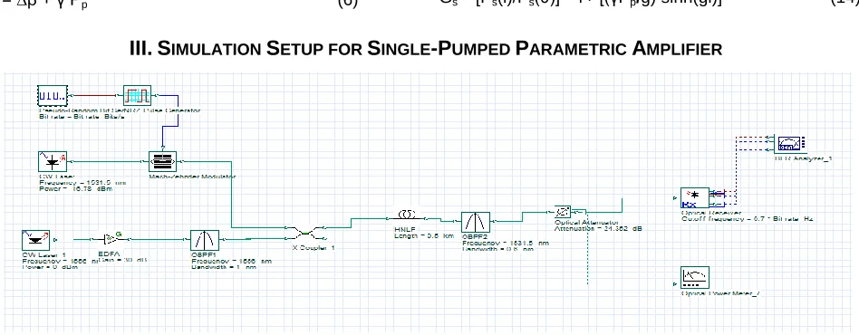
MPLIFIER383 Simulation setup of single-pumped parametric amplification for
NRZ format is illustrated in figure 2. In the setup, the input signal power of -16.78dBm is set from λs = 1522 to 1591nm
and is modulatedby10Gbps PBRS. The pump power of odBm is amplified by 30dB EDFA in order to achieve 30dBm and then 1nm optical band pass filter OBPF-1 is used to suppress amplified spontaneous emission (ASE) noise from EDFA. And 90% optical coupler is used to combine the signal and pump set at λp=1556nm. For this set up, the zero dispersion wavelength is 1554.5nm and the pump wavelength is placed near the ZDWL in order to satisfy the phase matching condition. Then, the combined signal is injected into the highly-nonlinear fiber (HNLF) where parametric amplification takes place. In this scheme, 0.5km-long HNLF of zero dispersion wavelength (ZDWL) at λ0 = 1554.5nm is used as a
nonlinear medium for FWM process. And 0.6nm of OBPF-2 is used for selecting the signal or notch filter rejecting the pump signal.
IV. P
ERFORMANCER
ESULTS FORS
INGLE-
PUMPED PARAMETRIC AMPLIFIERFigure 3. Comparison of two input signal power for signal’s gain curve
This figure (3) represents that the signal gain depend on the input signal power. In this case, the pump wavelength λp=1556nm is set as a fix. And signal wavelength is varied from 1522nm to 1591nm. From this fig, it is observed that signal gain is high at phase matching is zero when signal wavelength is 1531.5nm. And signal‘s gain is low as a dip when signal wavelength is close to the pump wavelength. At this wavelength phase matching is not zero. The signal gain is high at the signal wavelength is1581nm because phase matching is zero at this point. In this fig, the red line is at signal power 10µW and the blue line is at signal power 60µW. In this figure, signal achieves 31 dB gain and 50nm gain bandwidth. Therefore; parametric amplifier can provide high gain and wide gain bandwidth.
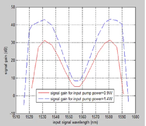
Figure 4. Comparison of two input pump power for signal’s gain curve
This figure (4) represents that the signal gain depend on the input pump power. In this case, the pump wavelength λp=1556nm is set as a fix. And signal wavelength is varied from 1515nm to 1595nm.From this fig, it is foundthat signal gain is high at phase matching is zero when signal wavelength is 1531.5nm. And signal‘s gain is low as a dip when signal wavelength is close to the pump wavelength.At this wavelength phase matching is not zero. The signal gain is high at the signal wavelength is1581nm because phase matching is zero at this point In this fig, the blue line means the signal‘s gain curve for input pump power = 1.4W and the red line means the signal‘s gain curve for input pump power = 0.9W.. In this figure, signal achieves 41dB gain and 70nm gain bandwidth for input pump power = 1.4W.
Figure 5. Signal gain profile for various input signal power
384 .And, the pump wavelength for both signals is 1556nm.From
this figure, it is foundthat the lower the signal power, the higher the signal gain can be achieved.
Figure 6. Signal gain profile for various input pump power
Figure (6) represents the effect of pump power on the signal gain. In this figure, the green line for signal wavelength 1581nm and the red line for signal wavelength 1531.5nm.And the pump wavelength for both signals is 1556nm.From this figure, it is observed that the higher the pump power, the higher the signal gain can be achieved.
V.
S
IMULATIONS
ETUP FORD
UAL-P
UMPEDP
ARAMETRICA
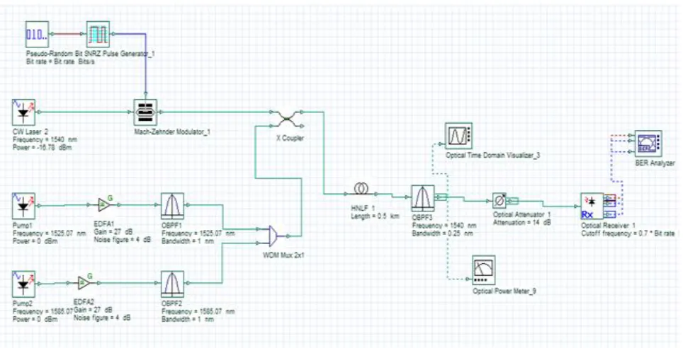
MPLIFIERSimulation setup of dual-pumped parametric amplification for NRZ format is illustrated in figure 7. In the setup, the input signal power of -16.78dBm is set from λs = 1520 to 1590nm
and is modulated by10Gbps PBRS.In this research, there are
two pump powers and each pump power of odBm is amplified by 30dB EDFA in order to achieve 30dBm and then 1nm optical band pass filter OBPF-1 and OBPF-2 are used to suppress amplified spontaneous emission (ASE) noise from EDFA. And90% optical coupler is used to combine the signal and two pumps set at λp1=1525.07nm and λp2=1585.07nm.
For this set up, the zero dispersion wavelength is 1554.5nm and the centre wavelength of the two pumps λc=1555 nm is placed near the ZDWL in order to satisfy the phase matching condition. Then, the combined signal is injected into the highly-nonlinear fiber (HNLF) where parametric amplification takes place. In this scheme, 0.5km-long HNLF of zero dispersion wavelength (ZDWL) at λ0 = 1554.5nm is used as a
nonlinear medium for FWM process. And 0.25nm of OBPF-3 is used for selecting the signal or notch filter rejecting the pump signal. Table (1) shows the parameters of highly nonlinear fiber in this proposed system.
TABLE I
PARAMETERS OF HIGHLY NONLINEAR FIBER USED IN THIS SYSTEM
Parameters of highly nonlinear fiber (HNLF)
Length 0.5km
Aeff 11µm
2
ZDWL,λ0 1554.5nm
Nonlinear
cofficient,γ 12.6W
-1
km-1
Attenuation 0.47 dB/km
385
IV. P
ERFORMANCER
ESULTSFOR
D
UAL-
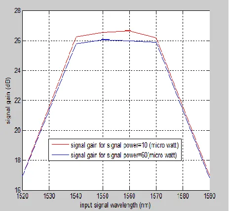
PUMPED PARAMETRIC AMPLIFIERFigure 8. Comparison of two input signal power for signal’s gain curve
This figure (8) represents that the signal gain depend on the input signal power. In this case, there are two pumps such as λp1=1525.07 nm, λp2=1585.07 nm andthe centre wavelength
of the two pumps is λc=1555 nmwavelength. And signal wavelength is varied from 1520nm to 1590nm. From this fig, it is observe that signal gain is high at the signal wavelength is 1540nm and 1570nm. And signal‘s gain is more flat than the signal‘s gain in single-pumped parametric amplifier. In this fig, the red line is at signal power 10µW and the blue line is at signal power 60µW. In this figure, signal achieves 26.5dB gain and 50nm gain bandwidth. Therefore; parametric amplifier can provide high gain and wide gainbandwidth.
Figure 9. Comparison of two input pump power for signal’s gain curve
This figure (9) represents the signal gain depend on the input pump power.In this fig, the blue line means the signal‘s gain
curve for input pump power = 1.4W and the red line means the signal‘s gain curve for input pump power = 0.9W. From this figure,it is observe that signal gain is high at the signal wavelength is 1540nm and 1570nm. And signal‘s gain is more flat than the signal‘s gain in single-pumped parametric amplifier.In this figure, signal achieves 36dB gain for input pump power = 1.4W.
Figure 10. Signal gain profile for various input signal power
Figure (10) represents the effect of signal power on the signal gain. In this figure, the red line for signal wavelength 1540nm and the green line for signal wavelength 1570nm. And, the center of the pump wavelength for both signals is 1555nm. From this figure, it is found that the lower the signal power, the higher the signal gain can be achieved.
Figure 11. Signal gain profile for various input pump power
386
V. C
ONCLUSIONThis work has accomplished single-pumped parametric amplifier and dual-pumped parametric amplifier for 10Gbps signals by using0.5km-long HNLF of zero dispersion wavelength (ZDWL) at λ0 = 1554.5nm . The results show that
31 dB of signal gain and 50nm of gain bandwidth are achieved in NRZ format for singlepumped and 26.5dB of signal gain and 50nm of gain bandwidth are achieve in NRZ format for dual-pumped parametric amplification. Therefore, it is observed that parametric amplifier can provide high gain and wide gain bandwidth. I t is observed that the signal gain in dual-pumped is more flat than the signal gain in single-pumped. So, the proposed parametric amplifier can be used for signal amplification in optical fiber communication.
A
CKNOWLEDGMENTThe author is greatly thankful to all her teachers from Department of Electronic Engineering, Mandalay Technological University.
R
EFERENCES[1] A. VEDADI, A. MUSSOT, E.LANTZ, H. MAILLOTE AND T.
SYLVESTRE
[2] E. K. ROTICH KIPNOO , D. WASWA, G. AMOLO AND
A.W.R.LEITCH
[3] G.P Agrawal, Nonlinear Fibres Optics, (Academmic Press, San Diego, 2001)
[4] J.Hansryd, P.A Andrekson, M.Westlund, J.Li, and P.O.Hedekvist, ―Fiber-based optical parametric amplifiers and their applications‖.
[5] M.N.Islam and O. Boyraz, ―Fiber parametric amplifiers for wavelength band conversion‖
[6] Armand vedadi et al, ‗Theoretical study of gain distortions in dual pump fiber optical parametric amplifiers‘.
[7] J Hansryd and P.A Andrkson, ‗Broad- band continuous wave pumped fiber optical parametric amplifier with 49dB gain and wavelength