A MODERN SELF QUANTIZING TECHNIQUE
ARCHITECTURES USING DISCRETE WAVELET
TRANSFORM FOR IMAGE PROCESSING
APPLICATIONS
Pothuri Sravana Priyanka
1, A.Narasimha Reddy
2,
L.Srinivas Reddy
3 1M.Tech Scholar (VLSI),
Nalanda Institute of Engg and Tech.
(NIET),
Siddharth Nagar, Guntur, A.P. (India)
2
Asst.professor (ECE),
Nalanda Institute of Engg and Tech.
(NIET),
Siddharth Nagar, Guntur, A.P. (India)
3
Assistant. Professor (ECE),
Nalanda Institute of Engg and Tech.
(NIET),
Siddharth Nagar, Guntur, A.P. (India)
ABSTRACT
This paper exists Precision-Aware approaches and related hardware implementations for performing the
operation of DWT. It includes implementation of BP architecture and DS design methodologies. These
methodologies will give the optimal utilization of hardware resources in the computation of Discrete Wavelet
Transform (DWT). Moreover, quantization of DWT coefficients to a precise target step size. It is performed as
an inbuilt part of the DWT computation, so eliminating the need to have a divide downstream quantization step
in applications like JPEG 2000. It concludes that DS design requires extensively less hardware resources with
increasing accuracy and DWT level when BS design exhibit natural speed is advances.
Keywords
— Digit Serial, Bit Parallel, Lifting Based DWT, Quantization, DWT
I. INTRODUCTION
Discrete wavelet transform (DWT) splits an image into multiple and small bands (sub bands) of low and high
frequency components. To compress an image, we need to encode these sub bands. This encoding technique and
main DWT technique gives us the total information of an image with less bits. Image compression is applicable
in the fields of entertainment, medical, defense, commercial, industrial domains and etc. DWT plays an
important role in image. DWT and Inverse DWT for Transformations are using in other image techniques like
image enhancement, image restoration and image filtering. DWT-IDWT is one of the well-known conversion
techniques that are extensively used in signal processing and communication applications. Discrete and inverse
discrete wavelet techniques are transforms signal into multiple promise sub bands. DWT is computationally
very exhaustive and requires power due to more number of arithmetical operations.
Latency and throughput are other foremost margins of DWT and it has compound levels of hierarchy. DWT was
conventionally implemented by convolution technique. The architecture complexity is depends upon the serial
or parallel digit representation of input data. As mentioned as an implementation requires large amount of
storage and large number of computations. It is for either low-power or high-speed applications. Newly, a
pass filters into a sequences of lower triangular matrices and translate the filter implementation into stripy
matrix.
The JPEG 2000 standard has good advantages over the original block DCT-based JPEG standard such as
significant coding efficiency and flexibility. The important element of JPEG 2000 is the discrete wavelet
transform (DWT), which recursively decomposes an input image into sub bands. Those sub bands has different
spatial frequency and point of reference. The most frequently used DWT filters in JPEG 2000 are the
bi-orthogonal I) lossless 5/3 integer and II) lossy 9/7 floating-point filter banks. In this document, we keep focus on
the DWT using 9/7 filter, which provides very good compression quality. But it is particularly challenging to
implement with high efficiency because of the reason is to the irrational personality of the filter coefficients.
II. LITERATURE SURVEY
The committee of JPGE has begun the investigation for finding another type of image compression technique
which will be useful for current and future applications. The committee has found one technique named JPGE
2000, is a compressive technique. It not only has higher compression efficiency compared to other systems like
baseline JPGE system but also provides new rich set of representation. In this technique, memory efficient block
DCT of JPGE has replaced by the full frame DWT (Discrete Wavelet Transform) and has low- complexity. The
DWT improves compression efficiency because of the reason is good energy compaction and also provides
image representation of multi-resolution.
There are so many themes on the different types of hardware implementations of the DWT algorithm and the
novel DWT algorithm. Those articles have paid very less immersion to the meticulousness computation of the
DWT. We can consider it as a design goal. Some articles are comparatively comprises few treatments for this
problem. The work in “Quantization effect on VLSI implementations for the 9/7 DWT filters” presents a novel
architecture for 1-D and 2-D DWT by using lifting schemes. To achieve the goal of low and high - frequency
component of original data being available alternately, this has designed. The effects of quantizing the lifting
coefficients of the 9/7 DWT has achieved in the previous article. The possessions on the peak signal-to-noise
ratio (PSNR) and hardware area/speed are evaluated from the number of canonical signed digit (SD) terms for
the coefficients are varied. After this another article has conducted a similar analysis but it is with the fixed –
point data path fixed to 12 bits of integer and the same bits of fractional accuracy. It provides adequate dynamic
range, which is useful to compute a six-level DWT over 50 dB PSNR.
In difference to the preceding work, which has been mainly directed to filter coefficients, in this paper, we
lecture to synchronized optimization of not only the coefficient precision but also the internal data paths, which
have used in their computation and for that purpose we present a solution that is fully generalized with stare to
accuracy, allowing design of a DWT to any desired precision. The optimization technique can be able to use for
minimization of the operand bit width in a bit parallel (BP) architecture and also to use for minimization of
iterations in digit- serial (DS) architecture. This facilitates implementations with a considerable improvement in
hardware resources and/or execution times while also make a sure that overflows are avoided and requirements
of precision should be met.
This presentation includes sections as follows: Top level architecture of the DWT design in Section III,
lifting-based DWT and JPEG2000 quantization in discussed in Section IV, proposed design has explained in the
III. OP LEVEL ARCHITECTURE
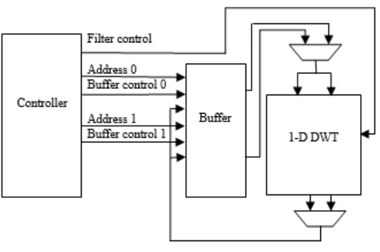
Fig 1: Generic High-Level Architecture of the DWT Design
The figure represents the generic high level architecture of the DWT design. In figure, the 1-D DWT module
performs the actual operation of DWT, which can be implemented by bit parallel (BP) architecture. Here the
buffer is a dual-port. It holds two data frames, which can be used to store the original raw data, intermediate data,
and /or the final transformed data. Another important module: the controller is used to control the whole
operation of design. It has done by creating control signals for the buffer and also for the filter.
IV. LIFTING BASED DWT
4.1 Lifting
The lifting scheme based DWT has been integrated in the forthcoming JPEG2000 standard because it
diminishes the arithmetic complexity of the conventional as compared with the convolution based DWT.
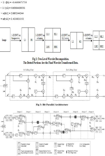
Fig.2 gives you an idea about the procedure for performing a two level DWT on an image. The 1-D DWT carry
out the actual wavelet transform by first performing the row wise operation on the image to produce low
frequency L1 and high- frequency H1 components. After performing 1-D DWT again on the columns of L1 and
H1, the first level of decomposition has to complete on those components, then we got LL1, HL1, LH1, and
HH1. This process can be repeated on LL1 to produce the LL2, HL2, LH2, and HH2 sub bands.
Actually the 9/7 DWT was implemented depending on convolution-based methods. Generally low pass and high
pass filters are used in convolution-based methods. Afterwards Daubenchies and Sweldens proved that DWT
can be decomposed into a finite sequence of lifting steps. It provides several advantages like lower computation
and memory requirements and also easier boundary management explained in “A survey on lifting-based
discrete wavelet transform architectures” over the convolution based one. Hence here we are using a lifting
based 9/7 DWT.
Fig.3 illustrates the flipping structure of 9/7 DWT designed by Haung, explained in the article “Flipping
structure: An efficient VLSI architecture for lifting based discrete wavelet transform (DWT),” for the purpose of
lifting-based 1-D DWT. The flipping structure shares the identical computational complexity with the traditional
lifting scheme. This flipping structure diminishes the critical path by flipping some computation units with the
C1= 1/ (αβ) = 0.7437502472
C2 = 1/ (βγ) = -0.6680671710
C3= 1/ (γδ) = 0.6384438531
C4 = αβδ/δ = 2.065244244
C5 = αβγδδ = 2.421021152
Fig 3: Bit Parallel Architecture
4.2 Quantization
Quantization engaged in image processing is a lossy compression technique. It can be accomplished by
compressing a range of values to a single quantum value i.e., fixed value. One stream can be compressible by
reducing the number of discrete symbols in that stream. For example, reduce the file size when you need to
represent an image, in place of reducing the number of colours, we can go for it. Precise applications include
DCT data quantization in JPEG and DWT data quantization in JPEG 2000.
The key element for the lossy 9/7 DWT when achieving compression performance is Quantization. As per the
previous presentation, uniform dead-zone quantization has supported by the JPEG 2000 standard and also it
supports Trellis coded quantization. Because of the simplicity and hardware efficiency, we are selecting
Uniform dead-zone quantization.
This quantization procedure utilizes bins, which have identical in size except only for a “dead zone” quantizer
centred at zero, has the size of a double of the others. For example, by using this quantization scheme, if n bits
of precision for HL1, LH1 and HH1, then there should be the n + 1 bits of precision for LL2, HL2, LH2 and
HH2 as clarified from the presentation of “Precision for 2-D discrete wavelet transform processors”.
V. PROPOSED ARCHITECTURE
It is desirable to minimize the bit-widths for all variables in the data paths, most important to reduction of size in
tables, and operators, for instance adders and multipliers. Here we are using a bit width minimization scheme. It
can able to minimize bit-widths while make sure that the results meet the one ulp error bound requirement. We
have to split the problem of minimizing fixed-point bit-widths into two kinds of parts: range analysis followed
by precision analysis. These two different parts are performed totally within MATLAB framework, making use
of the finite precision hardware emulation models and an arithmetical approach is taken to undertake the range
and precision minimization problems. Range analysis engages checking the dynamic range and totalling the
bit-widths of the integer parts.
Overflows or underflows and excessive bits cause waste valuable hardware resources happen because of the
insufficient bits for the range. Simulation-based approach can be used by the range analysis design is forwarding
with a bulky set of random numbers. It ranges over not only the interval of possible values for the particular
input, but also including the extreme values of that interval.
Coming to BP approach the primary goal is computing speed, the design challenge is determining the suitable
number of integer and fractional bits to use in representing all the signals, which has utilized during the
computation. For signal z, the number of integer bits are denoted by IBz, fractional bits are denoted by FBz and
the total number of bits has denoted by Bz, where Bz = IBz + FBz.
5.1 Integer Bit- Width Determination
The IB can be determined by using an approach. The approach is based on computing the roots of the
derivatives of each signal. Since the binary point needs to be associated for additions, the two addition operands
have to to share the same IB. As per this phenomena, for the 1-D DWT, which has shown in Fig. 3, the following signal
5.2 Fractional Bit-Width Optimization
The fractional bit-width optimization is carried out in two steps, one is a static step based on analytical models,
for which to obtain the set of widths, and a dynamic step is based on simulation that further diminish the bit
width using a PSNR delta threshold. The target precision metric (ulp) error criterion is one of the beat ways to
specify the worst case (maximum absolute) error. The static step finds the set of bits that guarantee less than
2-ulp error at the final outputs of quantized DWT.
5.3 Static Optimization
The worst case (maximum absolute error) quantization errors for truncation and round-to-nearest are given by
Truncation: Ez = max (0, 2-FBz -2FBz’) …(1)
Round-to-nearest: Ez = {0, if FBz ≥ FBz’ 2-FBz – 1, otherwise} … (2)
Where FBz’ is the un- quantized full precision.
Esi = max (D11) × 2-FBc5-1 + C5× ED11 + ED11 × 2-FBC5 – 1 + max (0, 2-FBsi -2-FBc5 – FBD11)… (3)
Edi = max (D9) × 2-FBC4 – 1 + C4 × ED9 + ED9 × 2-FBC4-1 + max (0, 2-FBdi -2 –FBc4 – FBD9)... (4)
Here these error expressions consider as the worst case error bounds at each node and can be recursively
obtained for any number of DWT levels. Internal data paths bit widths are create using the error expressions in
conjunction with simulated annealing. Since the quantization scheme, which is of JPEG 2000 uses increasing
precision with i=L.
VI. DS DWT DESIGN
Fig. 4 illustrates the DS 1-D 9/7 DWT design. First, the incoming two’s complement data is serialized. After
that it has converted into SD representation. The serial SDs is after that passed into the DS DWT, which is
divided into nine pipeline stages that run in parallel. After the previous stage, the DWT-transformed data is
exchanged back into two’s complement representation and afterward parallelized into words. This approach can
have the ability to reduce the memory requirement. Because of the reason is two’s complement occupies half the
area of the equivalent SD representation. Both SD addition and SD multiplications creates one digit per cycle,
where starting from the most significant digit used for the static step is the unit in the last place.
The radix-2 SD redundant number system is used in the DS representations. SD operations do not propagate
carries because of redundancy. That's why they are able to run in most significant digit first (MSDF) mode. This
MSDF property makes it attractive for the DS DWT approach since it allows for varying the number of
iterations, which is to obtain different precision.
VII. IMPLEMENTATION RESULTS
We have designed this process in verilog HDL language. A main reason beyond using this language is easier
than any other HDL language and because of some of its salient features like it can able to allow the
functioned to the module.etc. The design has simulated using the standard simulation tool Xilinx. The results in
VIII. CONCLUSION
In this paper, precision-aware approaches and associated hardware implementations for performing the DWT
are presented. Both BP and DS design methodologies and also results have been showed. These methods can
use of an optimal amount of hardware resources in the DWT computation. In addition, this framework enables
quantization, which is usually performed after the DWT in algorithms such as JPEG 2000. We believe that the
design methods and architectures such as those presented in this presentation plays significant role in the design
of future energy- and precision-optimized DWT implementations.
REFERENCES
[1] M. Rabbani and R. Joshi, “An overview of the JPEG 2000 still image compression standard,” Signal
Process.: Image Commun., vol. 17, no. 1, pp. 3–48, Jan. 2002.
[2] Huang, P. Tseng, and L. Chen, “Flipping structure: An efficient VLSI architecture for lifting-based
discrete wavelet transform,” IEEETrans. Signal Process., vol. 52, no. 4, pp. 1080–1089, Apr. 2004. [3] K. Kotteri, S. Barua, A. Bell, and J. Carletta, “A comparison of hardware implementations of the bi
orthogonal 9/7 DWT: Convolution versus lifting,” IEEE Trans. Circuits Syst. II, Exp. Briefs, vol. 52, no. 5,
pp. 256–260, May 2005.
[4] Cheng and K. Parhi, “High-speed VLSI implementation of 2-D discrete wavelet transform,” IEEE Trans.
Signal Process., vol. 56, no. 1, pp. 393–403, Jan. 2008.
[5] B.Wu and C. Lin, “A high-performance and memory efficient pipeline architecture for the 5/3 and 9/7
discrete wavelet transform of JPEG2000 codec,” IEEE Trans. Circuits Syst. Video Technol., vol. 15, no.
12, pp. 615–1628, Dec. 2005.
[6] Xiong, J. Tian, and J. Liu, “Efficient architectures for two-dimensional discrete wavelet transform using
[7] N. Mehrseresht and D. Taubman, “An efficient content-adaptive motion- compensated 3-D DWT with
enhanced spatial and temporal scalability,” IEEE Trans. Image Process., vol. 15, no. 6, pp. 1397–1412,
Jun. 2006.
[8] S. Barua, K. Kotteri, A. Bell, and J. Carletta, “Optimal quantized lifting coefficients for the 9/7 wavelet,”
in Proc. IEEE Int. Conf.Acoust., Speech, Signal Process., 2004, vol. 5, pp. 193–196.
[9] V. Spiliotopoulos, N. Zervas, Y. Andreopoulos, G. Anagnostopoulos, and C. Goutis, “Quantization effect
on VLSI implementations for the 9/7 DWT filters,” in Proc. IEEE Int. Conf. Acoust., Speech, Signal
Process., 2001, vol. 2, pp. 1197–1200.
[10] K. Kotteri, A. Bell, and J. Carletta, “Design of multiplierless, high-performance, wavelet filter banks with
image compression applications,” IEEE Trans. Circuits Syst. I, Reg. Papers, vol. 51, no. 3, pp. 483–494,
Mar. 2004.
[11] A. Benkrid, K. Benkrid, and D. Crookes, “Optimal wordlength calculation for forward and inverse discrete
wavelet transform architectures,” Opt. Eng., vol. 43, no. 2, pp. 455–463, Feb. 2004.
[12] Daubechies and W. Sweldens, “Factoring wavelet transforms into lifting steps,” J. Fourier Anal. Appl.,
vol. 4, no. 3, pp. 247–269, May 1998.
[13] T. Acharya and C. Chakrabarti, “A survey on lifting-based discrete wavelet transform architectures,” J.
VLSI Signal Process., vol. 42, no. 3, pp. 321–339, Mar. 2006.
[14] M. Marcellin, M. Lepley, A. Bilgin, T. Flohr, T. Chinen, and J. Kasner, “An overview of quantization in
JPEG 2000,” Signal Process.: Image Commun., vol. 17, no. 1, pp. 73–84, Jan. 2002.
AUTHOR DETAILS
POTHURI SRAVANA PRIYNAKA, Pursuing M.tech (VLSI) from Nalanda institute
of Engineering and Technology (NIET), Siddharth Nagar, Kantepudi village,
satenepalli Mandal Guntur Dist.,A.P, INDIA. Her interest includes digital image
processing application with VLSI implementations.
A.NARASIMHA REDDY, he received his master degree in VLSI. His area of interest
includes CMOS analog design and VLSI system design. He currently working as Asst.
professor (ECE) from Nalanda institute of Engineering and Technology (NIET),
Siddharth Nagar, Kantepudi village, satenepalli Mandal Guntur Dist.,A.P,
L.SRINIVAS REDDY, He completed his post-graduation in DECS. His area of
interest includes digital electronics, digital communication, digital system design and
VLSI technology and design. His research areas are optimal communication
technology. He is currently working as Asst.professor (ECE) from Nalanda institute of
Engineering and Technology (NIET), Siddhartha Nagar, Kantepudi village, Satenepalli