292 | P a g e
MODELLING AND ANALYSIS OF EXISTING AND
MODIFIED CHASSIS IN TATA TRUCK
Darshit Nayak
1, Dr.Pushpendra KumarSharma
2, Ashish parkhe
31
M.tech Research Scholar,
2Guide & Head,
3Co-guide & Assistant Professor,
Mechanical Engineering Department, NRIIST, Bhopal M.P. (India)
ABSTRACT
Truck chassis forms the structural backbone of a commercial vehicle. The main function of the truck chassis is to
support the components and load that mounted on it. The chassis is experienced a stress whether when it ismoving
or in a static condition. This thesis presents an analysis of the static stress that acting on the upper surface of the
truck chassis. These projects study the distributions of the stress that acting on the chassis. Critical parts that will
lead to failure are also observed. The method used in this numerical analysis is finite element analysis (FEA). Finite
element analysis helps in accelerating design and development process by minimizing number of physical tests,
thereby reducing the cost and time for analysis. 3-D model of the truck chassis is made using ProE before analyzed.
Modal updating of truck chassis model is prepared adjusting the selective properties such as mass density and
Poisson’s ratio. Numerical results showed that critical part was at the mounting bracket of the tire and also at the
front part of the chassis. Some modifications are also suggested to reduce the stress and to improve the strength of
the truck chassis. Finally optimum section is suggested.
Keywords: Modelling, Ansys, Chassis, Frame Work
I INTRODUCTION
The chassis is the framework to which everything is attached in a vehicle. In a modern vehicle, it is expected to fulfill the following functions:
Provide mounting points for the suspensions, the steering mechanism, the engine and gearbox, the final
drive, the fuel tank and the seating for the occupants Provide rigidity for accurate handling;
Protect the occupants against external impact.
293 | P a g e
longitudinal side member, front, rear and intermediate member, diagonal member
While fulfilling these functions, the chassis should be light enough to reduce inertia and offer satisfactory performance. Modelling and analysis is carried out for the existing and modified design. The model is prepared in pro-e software and inserted in the ansys software for the static analysis.
II MODELLING AND ANALYSIS OF EXISTING CHASSIS
In Table II.1 represents the unit used in modelling analysis.
TABLE II.I Unit Used In Modelling Analysis
Unit System Metric (mm, kg, N, °C, s, mV, mA)
Angle Degrees
Rotational Velocity rad/s
Table II.2 represents the model geometry of truck chassis.
TABLE II.IIThe model geometry of truck chassis.
Model > Geometry
Object Name Geometry
State Fully Defined
Definition
Source D:\project\chasis_1613\trial\c section\long_beam.stp
Type Step
Length Unit Meters
Element Control Program Controlled
Display Style Part Color
Bounding Box
Length X 7720. mm
Length Y 254. mm
Length Z 900. mm
Properties
Volume 4.1522e+007 mm³
Mass 324.95 kg
Statistics
Bodies 1
Active Bodies 1
Nodes 20581
Elements 9738
Table II.III represents the model geometry parts of truck chassis.
TABLE II.III The model geometry parts of truck chassis Model > Geometry > Parts
Object Name LONG_BEAM State Meshed Graphics Properties
294 | P a g e
Transparency 1
Definition
Suppressed No
Material St37
Stiffness Behavior Flexible Nonlinear Material Effects Yes
Bounding Box
Length X 7720. mm
Length Y 254. mm
Length Z 900. mm
Properties
Volume 4.1522e+007 mm³
Mass 324.95 kg
Centroid X -3825. mm Centroid Y 110.06 mm Centroid Z -450.01 mm Moment of Inertia Ip1 4.7337e+007 kg·mm² Moment of Inertia Ip2 1.7547e+009 kg·mm² Moment of Inertia Ip3 1.702e+009 kg·mm²
Statistics
Nodes 20581
Elements 9738
Table II.IV represents the material property of truck chassis.
TABLE II.IVThe material property of truck chassis.
St37 > Constants Structural
Young's Modulus 2.1e+005 MPa Poisson's Ratio 0.29
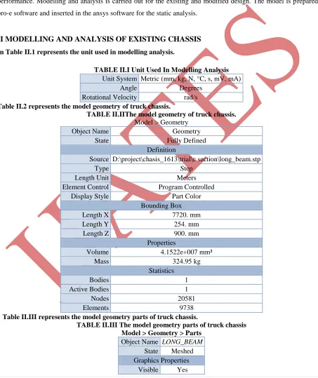
To carry out of the static analysis themodelling of Tata turbo truck se1613 is prepped in the pro-e software then is inserted in ansys software for static analysis that is show in figure 1.
295 | P a g e
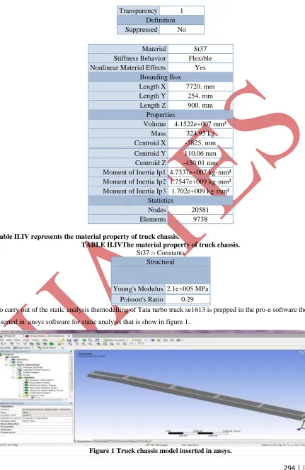
To carry out the static analysis first of all the meshing of model is to be done that is show in figure 2.Figure 2 Meshing of truck chassis.
TABLE II.VThe mesh applied to chassis of truck.
Model > Mesh
Object Name Mesh
State Solved
Defaults
Physics Preference Mechanical
Relevance 0
Advanced
Relevance Center Medium
Element Size Default
Shape Checking Standard Mechanical
Solid Element Midside Nodes Program Controlled
Straight Sided Elements No
Initial Size Seed Active Assembly
Smoothing Low
Transition Fast
Statistics
Nodes 20581
296 | P a g e
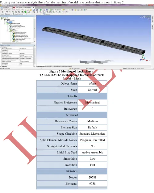
Now the boundary conditions are applied to this chassis that is shown in figure 3.Figure 3 Boundary condition applied on truck chassis model.
The equivalent stresses are checked on the application of load to the chassis that is shown in figure 4.
Figure 4 Equivalent stress produced in model.
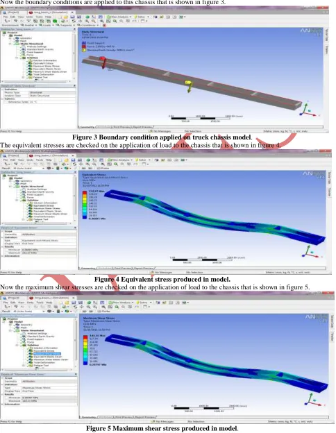
Now the maximum shear stresses are checked on the application of load to the chassis that is shown in figure 5.
297 | P a g e
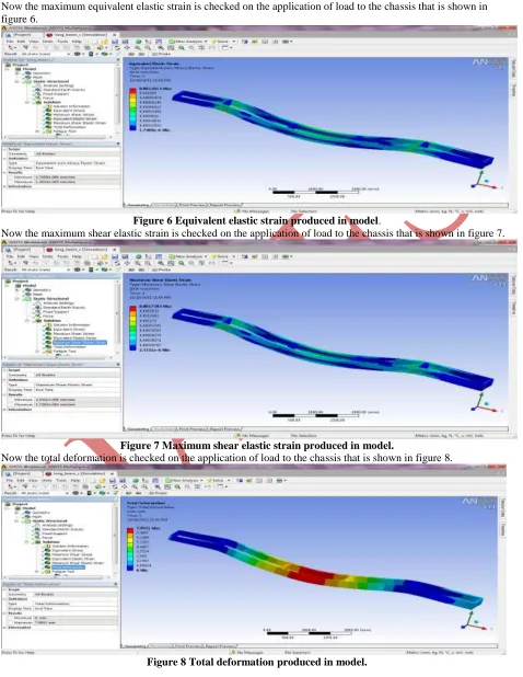
Now the maximum equivalent elastic strain is checked on the application of load to the chassis that is shown in figure 6.Figure 6 Equivalent elastic strain produced in model.
Now the maximum shear elastic strain is checked on the application of load to the chassis that is shown in figure 7.
Figure 7 Maximum shear elastic strain produced in model.
Now the total deformation is checked on the application of load to the chassis that is shown in figure 8.
298 | P a g e
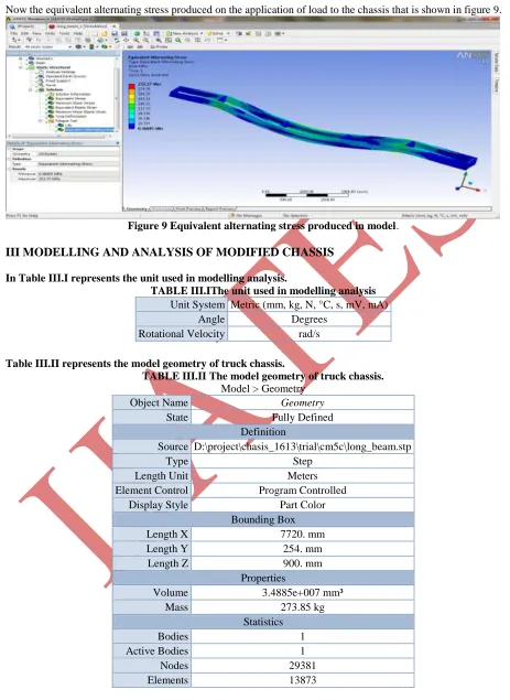
Now the equivalent alternating stress produced on the application of load to the chassis that is shown in figure 9.Figure 9 Equivalent alternating stress produced in model.
III MODELLING AND ANALYSIS OF MODIFIED CHASSIS
In Table III.I represents the unit used in modelling analysis.
TABLE III.IThe unit used in modelling analysis
Unit System Metric (mm, kg, N, °C, s, mV, mA)
Angle Degrees
Rotational Velocity rad/s
Table III.II represents the model geometry of truck chassis.
TABLE III.II The model geometry of truck chassis.
Model > Geometry
Object Name Geometry
State Fully Defined
Definition
Source D:\project\chasis_1613\trial\cm5c\long_beam.stp
Type Step
Length Unit Meters
Element Control Program Controlled
Display Style Part Color
Bounding Box
Length X 7720. mm
Length Y 254. mm
Length Z 900. mm
Properties
Volume 3.4885e+007 mm³
Mass 273.85 kg
Statistics
Bodies 1
Active Bodies 1
Nodes 29381
299 | P a g e
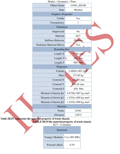
Table III.III represents the model geometry parts of truck chassis.
TABLE III.IIIThe model geometry parts of truck chassis
Model > Geometry > Parts
Object Name LONG_BEAM
State Meshed
Graphics Properties
Visible Yes
Transparency 1
Definition
Suppressed No
Material St37
Stiffness Behavior Flexible Nonlinear Material Effects Yes
Bounding Box
Length X 7720. mm
Length Y 254. mm
Length Z 900. mm
Properties
Volume 3.4885e+007 mm³
Mass 273.85 kg
Centroid X -3824.2 mm
Centroid Y 109.65 mm
Centroid Z -450. Mm
Moment of Inertia Ip1 4.6726e+007 kg·mm² Moment of Inertia Ip2 1.4781e+009 kg·mm² Moment of Inertia Ip3 1.4352e+009 kg·mm²
Statistics
Nodes 29381
Elements 13873
Table III.IV represents the material property of truck chassis.
TABLE III.IVthe material property of truck chassis
St37 > Constants
Structural
Young's Modulus 2.1e+005 MPa
300 | P a g e
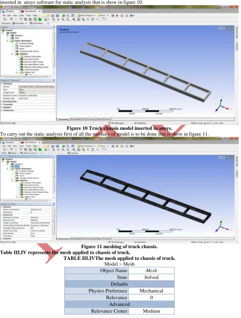
To carry out of the static analysis the modelling of Tata turbo truck se1613 is prepped in the pro-e software then is inserted in ansys software for static analysis that is show in figure 10.Figure 10 Truck chassis model inserted in ansys.
To carry out the static analysis first of all the meshing of model is to be done that is show in figure 11.
Figure 11 meshing of truck chassis. Table III.IV represents the mesh applied to chassis of truck.
TABLE III.IVThe mesh applied to chassis of truck.
Model > Mesh
Object Name Mesh
State Solved
Defaults
Physics Preference Mechanical
Relevance 0
Advanced
301 | P a g e
Element Size DefaultShape Checking Standard Mechanical Solid Element Midside Nodes Program Controlled
Straight Sided Elements No Initial Size Seed Active Assembly
Smoothing Low
Transition Fast
Statistics
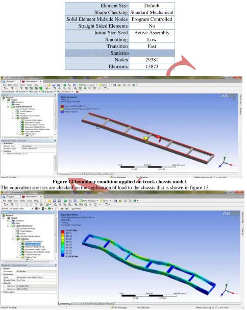
Nodes 29381
Elements 13873
Figure 12 boundary condition applied on truck chassis model.
The equivalent stresses are checked on the application of load to the chassis that is shown in figure 13.
302 | P a g e
Now the maximum shear stresses are checked on the application of load to the chassis that is shown in figure 14.Figure 14 maximum shear stress produced in model.
Now the maximum equivalent elastic strain is checked on the application of load to the chassis that is shown in figure 15.
Figure 15 equivalent elastic strain produced in model.
Now the maximum shear elastic strain is checked on the application of load to the chassis that is shown in figure 16.
303 | P a g e
Now the total deformation is checked on the application of load to the chassis that is shown in figure 17.Figure 17 total deformation produced in model.
Now the equivalent alternating stress produced on the application of load to the chassis that is shown in figure 18.
Figure 18 equivalent alternating stress produced in model
IV COMPARISON
304 | P a g e
TABLE IV.I Comparisons of different stress value
Sr.
No. Model Type
Von-misses strain Maximum shear strain Von-Misses
stress Equivalent stress
Maximum shear stress
1 Existing C section 0.0012 0.001758 252.27 252.77 143.11
2 Modification C
section 0.0007 0.000979 143.11 143.11 79.681
TABLE IV.II Comparisons of Different parameter in existing and modified design Sr.
No. Model Type Mass Thickness cross member Deformation
1 Existing C section 325.95 6.35 6 7.9951
2 Modification C
section 273.85 5 7 4.1313
From the comparison it is clear that after the modification Von-Misses stress, Maximum shear stress, Von-misses strain, Maximum shear strain, Equivalent stress are less than the existing design.
V CONCLUSION
To different model are checked for loading condition 198652.5 N
In the case of existing design when the load of 198652.5 N is applied on the model as the result of that von misses stress 252.27MPa, maximum shear stress 143.11 MPa, von misses strain 0.0012 mm/mm, Maximum shear strain 0.001758 mm/mm, Equivalent stress 252.77 MPa.
In the case of modified design when the load of 198652.5 N is applied on the model as the result of that von misses stress 143.11 MPa, maximum shear stress 79.681 MPa, von misses strain 0.0007 mm/mm, Maximum shear strain 0.000979 mm/mm, Equivalent stress 143.11 MPa.
From the result it is clear that modified design is superior as compare to existing design.
REFERENCES
[1] “Stress Analysis Of Heavy Duty Truck Chassis As A Preliminary Data For Its Fatigue Life Prediction Using
Fem” RoslanAbd Rahman, Mohd Nasir Tamin, OjoKurdi*JurnalMekanikal December 2008, No. 26, 76 – 85
[2] “APPLICATION OF DYNAMIC CORRELATION TECHNIQUE AND MODEL UPDATING ON TRUCK
CHASSIS” Izzuddin bin Zaman @ Bujang*,RoslanAbd. Rahman+
[3] “Structural Durability Of Forged Automotive Aluminium Chassis Components Submitted To Spectrum Loading
And Salt-Corrosion By Theexample Of A Tension Strut” N. Hägele a, c.m. Sonsinoba*
[4] “USE OF FINITE ELEMENT TECHNIQUE FOR THE ANALYSIS OF COMPOSITE STRUCTURES” R. Ali