Research on Variable Structure Control Strategy
Based on Direct BUCK AC-AC Converter
Xin Geng
Key Laboratory of Control of Power Transmission and Conversion, Ministry of Education Department of Electrical Engineering, Shanghai Jiao Tong University
Shanghai, China [email protected]
Houjun Tang, Liangyu Bai, Nan Jin
Key Laboratory of Control of Power Transmission and Conversion, Ministry of Education Department of Electrical Engineering, Shanghai Jiao Tong University
Shanghai, China
[email protected], [email protected], [email protected]
Abstract—The researches on direct AC-AC convertors have been an important field. The DC-modulated method, which was used in DC-DC convertors before, is used in AC-AC convertors to realize a direct AC-AC converting now. The method as regulating the duty of switch periods can control the circuit to output an acceptable sinusoid voltage wave. But this method can always bring forth a small phase shift between input and output. In this paper, variable structure control (VSC) is used in BUCK circuit. Simulations for these different control strategies based on the Simulink platform are used to analyze and compare. The result shows that the VSC can reduce the phase shift hardly to zero. In the same time, the switch period of VSC is not unchanged. It’s changing following the error. Compared to PWM control method, the VSC can gain a smaller response time and a balance between reducing switching loss and improving quality of output.
Index Terms—AC-AC converter, Buck, PID, VSC, control stragety
I. INTRODUCTION
The researches on direct AC-AC convertors have been an important field. Compared with the traditional AC-DC-AC convertors, the direct AC-DC-AC-AC-DC-AC convertors in which the energy-storage component is not equipped can be manufactured smaller and cheaper.
Furthermore, the direct AC-AC convertors have been widespread concern and in-depth research for its quick response, single-stage transformation, and outputting AC voltage without low orders harmonics.
Recent years, the development of Smart Grid needs smarter transformers to make the grids more controllable and more efficient. It is likely that future power generation and distribution will involve a lot of distributed renewable energy resources and power grids. The need for power semiconductor devices with high-voltage, high-frequency, and high-temperature operation capability is growing. The AC-AC convertor can contribute more for the Smart Grid in the future.
Nowadays, several kinds of basic topologies can be applied to realize a direct AC-AC convertor. Such as Buck, Boost, Buck-Boost, Z-Source, Quasi Z-Source, Push-Pull, and so on.[1-5]
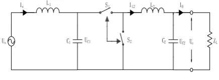
The Figure 1 is the Buck-Type AC-AC convertor. It can support a controlled output AC voltage source which is smaller than the input AC voltage source. The amplification factor K is smaller than 1.
Figure 1. The Buck-Type AC-AC converter
The figure 2 is the Boost-Type AC-AC convertor. The amplification factor K of Boost circuit is bigger than 1.
Figure 2. The single-stage Boost-Type AC-AC convertor
The figure 3 is the Buck-Boost-Type AC-AC convertor. The amplification factor K of Buck-Boost-Type circuit is less than 0.
Figure 3. The Buck-Boost-Type AC-AC convertor
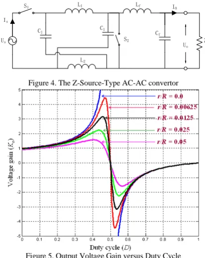
theory. It is different from above convertors that the Z-Source AC-AC convertor can output not only the in phase voltage but also the inverse voltage just like the showing in Figure 5.
Us
L1
C1
S1
S2 ZL
Is Cf IO L2 Lf C1 Uo
Figure 4. The Z-Source-Type AC-AC convertor
Figure 5. Output Voltage Gain versus Duty Cycle
These topologies have a common characteristic that each of them contains two relatively complementary bi-directional switches. So, each of these circuits has two different state equations.
The buck type and boost type circuits are the basic topologies on which other topologies are developed. So the control strategies of Buck and Boost topologies almost can be easily applied in other topologies.
The buck circuits can be regulated linearly. But it can only output lower voltage than input voltage. On the contrary, the boost circuit can output higher voltage, even infinity in theory, but its model is nonlinear. In most engineering, the function of boost voltage is not necessary and controllability is more important. So the buck circuits are applied more widely than the boost circuits.
There are several control strategies which can be used in the buck circuits, just like the constant duty chopper, the PID/PI controlling, the neural networks controlling, and so on. [6-8]
In these traditional control strategies, the core is controlling the duty in one switch period. The PWM technology which used in the DC switching power supply is applied to realize AC-AC converter.
In this paper, variable structure control (VSC) strategy is applied. This method is different from those traditional control methods. There is no longer the duty concept. The VSC controls the circuit changing between two different structures to gain a faster response speed. This control method has been used in comprehensive fields successfully, but hardly been used in direct AC-AC converter. The simulations have been done to analyze and compare the control strategies and show the advantages of VSC.
II. THE BUCK CIRCUIT MODEL
A. State-Space Model
The typical buck circuit is shown in the Figure 1. The two switches S1 and S2 are both bi-directional switch and
the two realizations of bi-directional switch are given in the Figure 6. In the following simulation the Figure 6(b) is adopted.
(a) (b)
Figure 6. Bi-directional Switch
Since the dead time and the follow current problem for buck circuits have been solved perfectly, they are ignored in this paper. The switch S1 and S2 are ideal switches and
they close complementarily.
When S1 is closed and S2 is opened. The state equation
of the buck circuit is equation (1).
1 1 2 1 2 2 2 1 1 1 2 1 2 2 2 1 ( ) 1 ( ) 1 ( ) 1 ( ) C L L c L O L s C L C C O C dU I I dt C dU I I dt C dI U U dt L dI U U dt L U U ⎧ = − ⎪ ⎪ ⎪ = − ⎪ ⎪ ⎨ ⎪ = − ⎪ ⎪ ⎪ = − ⎪⎩ =
. (1)
When S1 is opened and S2 is closed. The state equation
of the buck circuit is equation (2).
1 1 1 2 2 2 1 1 1 2 2 2 2 1 1 ( ) 1 ( ) 1 ( ) C L c L O L s C L C O C dU I dt C dU I I dt C dI U U dt L dI U dt L U U ⎧ = ⎪ ⎪ ⎪ = − ⎪ ⎪ ⎨ ⎪ = − ⎪ ⎪ ⎪ = − ⎪⎩ =
. (2)
1 1 2 1 2 2 2 1 1 1 2 1 2 2 2 1 ( ) 1 ( ) 1 ( ) 1 ( ) C L L c L O L s C L C C O C U I DI T C U I I T C I U U T L I DU U T L U U Δ ⎧ = − ⎪ ⎪ Δ ⎪ = − ⎪ ⎪ ⎨ Δ ⎪ = − ⎪ ⎪ Δ ⎪ = − ⎪⎩ =
. (3)
In the equation (3), D is the duty of one switch period and T is the switch period. When the L1, L2, C1 and C2 are
large enough, the UC1, UC2, IL1, IL2 can be seen as constant
or change a little in one switch period. Then the equation (4) can be seen right.
1 2 2 1 1 2 2 0 0 0 0 L L L O s C C C O C I DI I I U U DU U U U − = ⎧ ⎪ − = ⎪ ⎨ − = ⎪ ⎪ − = ⎩ =
. (4)
In fact, the equation (4) is just an approximatively correct equation. Because the switch frequency is much higher than the frequency of AC voltage source (50Hz), it is assumes that the input voltage can be seen as a DC source in several switch periods time. In the other hand, the parameters of L1, L2, C1 and C2 are must be large
enough. So the ripple waves of UC1, UC2, IL1 and IL2 can be
small enough to be ignored.
Almost all traditional control strategies are based on the equation (3) and equation (4). But the VSC is different and will be discussed in behind section.
B. Other Models
There are also some other mathematical modeling to describe the Buck converter. Many experts such as Sira-Ramirez, Czarkowski, Ilic, Cuk, Middlebrook, Lee, Smedley, Cheng and Erickson devoted in mathematical modeling[9-20].
In traditionally, the switch function is replaced by its Taylor series. Then the nonlinear equation can be changed to a linear one. But, in this case, the duty must be a constant. It can only describe the steady-state characteristic well.
Energy storage in power electronics converters has been paid attention long time ago. The professor Luo FangLin proposed a new method of modeling the Buck circuit in 2004. He had theoretically defined a new concept – energy factor (EF) and researched the relations between EF and the mathematical modeling for power electronics converter[21]. This theory is available for complex structure converters. But it’s also not successful to describe the dynamical property of power electronics converters well.
III. TRADITIONAL CONTROL STRATEGIES
The traditional control strategies are based on duty controlling. The switch frequency is set and the duty is controlled. In this place, constant duty control and PID control are discussed simply to show the characteristic of traditional control strategies.
A. Constant Duty
Base on the equation (4), when the D is a constant value between 0 to 1, 0<D<1, equation (5) can be gained.
2 1 1 2 2 1 1 L L C S O L
O C C S
I I
D
U U
I I
U U DU DU
⎧ = ⎪ ⎪⎪ = ⎨ ⎪ = ⎪ = = = ⎪⎩
. (5)
This is the most fundamental direct AC-AC converter. The Figure 7 is shown the model of Simulink.
Figure 7. The Simulink Circuit about Constant Duty Control Strategy
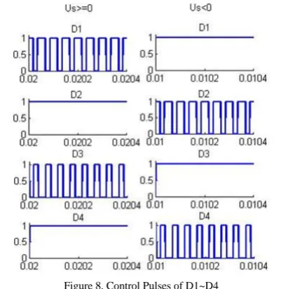
The control pulses of D1~D4 is shown in Figure 8. When the US>=0, D1 and D3 was closing alternately, D2
and D4 kept closing. On the contrary, when the US<0, D2
and D3 was closing alternately, D1 and D3 kept closing.
Figure 8. Control Pulses of D1~D4
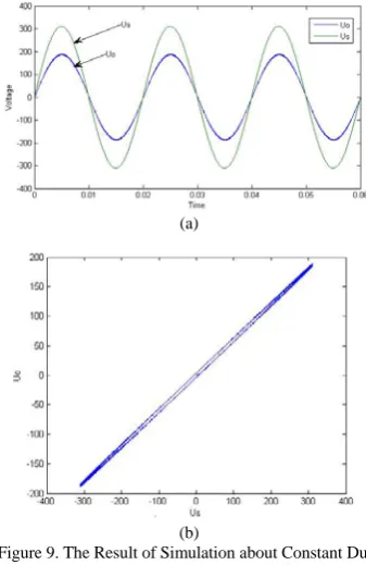
The Figure 9 is the result of the simulation for constant duty.
According to the equation (5), the relation between US
that there is a phase difference between UO and US.
Because the trace in Figure 9(b) is moved anticlockwise, the phase of UO lagged the phase of US.
This phase shift can be explained by equation (1)(2) (3). In each switch period, the instantaneous value of US can
only decided the next switch period value of IL1, so the IL1
changed behind the US. And so on, the UC1 changed behind
the IL2 and the UO changed behind the IL2.
In another word, the UO needs a response time to follow
the changing of US.
(a)
(b)
Figure 9. The Result of Simulation about Constant Duty
At the same time, when the Duty is a constant value, the amplification factor between US and UO is also a constant
value. It means that, when the US is unstable, the UO would
be unstable too, just like the simulation results in figure 10.
Figure 10. The Simulation Results of a Unstable Input US.
From the Figure 10, the input source US contains a
11-order harmonic. This 11-11-order harmonic can transmit from the input port to the output port directly.
B. PID Control
Based on above analysis, the PID converter control the duty D dynamically instead the constant duty to get a better output wave. PI or PID control based on traditional control theory is used to control the D.
Since D is no longer a constant, the system is converted into a time-varying system.
The Figure 11 is the simulation model. The PWM1H is the control pulse of D1, the PWM2H is the control pulse of D2; the PWM1L is the control pulse of D3; the PWM2L is the control pulse of D4.
Figure 11. PID Controller
It can be seen from the equation (3) that the duty D and the input US decide the output UO together. Even when the
instantaneous value of US is closed to zero the PID
controller can hardly reduce the error. So the error between Utarget and UO is divided by the absolute value of US to get
a more reasonable error value.
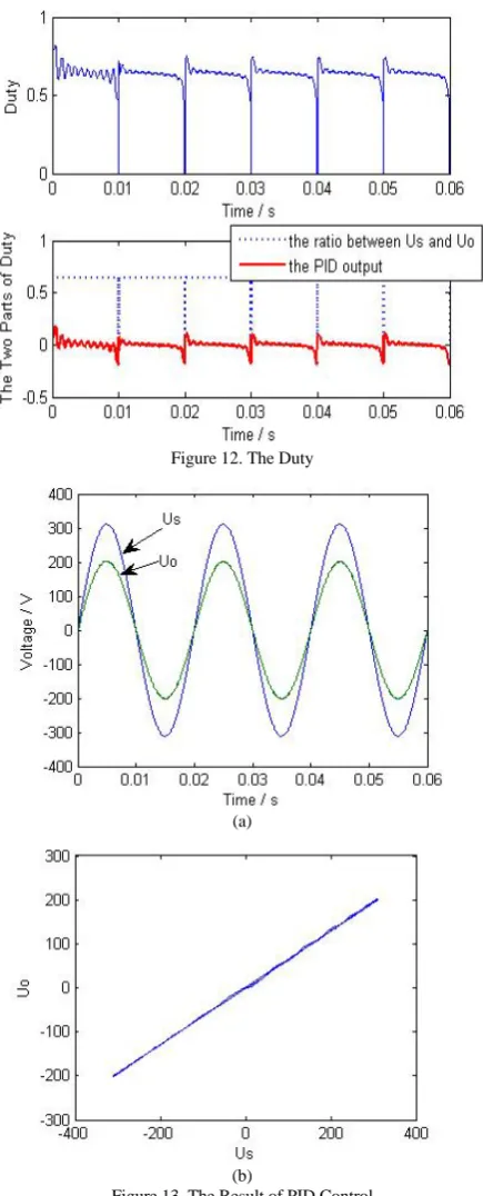
The duty D is comprised of two main parts. One part is the ratio between US and UO, the other part is the output of
PID controller with error inputting. The first part is a constant value in conventional practice. The Figure 12 is shown the duty D.
In this control strategy, PID control is used to correct the Duty. The Figure 13 is the simulation results of US and
UO.
In the Figure 13(b), it is clear that there is a oscillating process. And from the Figure 12, this oscillating process
needs about 0.01s. And then, the trace is almost a line with a small oscillation. The small oscillation can be seen more clearly from the wave of PID output which has been shown in Figure 12.
Compared to the constant duty, the PID controller can reduce the phase delay between US and UO. But it needs a
short cycle to wait for the integral part working. But the PID controller can regulate the Duty to reduce error in time, it can control the output voltage UO as a ideal sine wave
Figure 12. The Duty
(a)
(b)
Figure 13. The Result of PID Control
The Figure 14 is the simulation result about a input voltage with 11-order harmonic and the Figure 15 is the Duty controlled by PID controller.
Figure 14. Voltage Waves of Simulation with 11-Order Harmonic
Figure 15. Duty Wave of PID controller
All the traditional control strategies are based on controlling the duty D. The above two are just two fundamental control strategies. There are also many other derived control methods. But they can be analyzed through the equation (3).
IV. VARIABLE STRUCTURE CONTROL
Whichever the constant duty control and the PID controller, their switch frequencies are all unchanged. But the variable structure control (VSC) and the first two control strategies are completely different.
The VSC controls the switches in a different way. The switch frequency and duty are ignored and a judge function
S U U U
(
S,
O,
target)
is used to decide the state ofswitches.
The Utarget is the voltage wave which the system wants
to output. In another word, the Utarget is the purpose of the
UO.
From the equation (1) and equation (2), it can be seen that the two states of switches stood for two different circuit structures. The equation (1) stands for the structure with voltage source input and the equation (2) stands for the structure without voltage source input.
The function
S U U U
(
S,
O,
target)
is designed to help the controller to know whether the voltage source would be needed.As the equation (6), it is the simplest VSC switching function S.
arg
t et O
S
=
U
−
U
. (6)arg
0
t et O
S
=
U
−
U
=
. (7)For D1~D4, defined:
1,
is closed;
(
1, 2, 3, 4; )
0,
is opened;
i
Di
D
i
Di
⎧
=
⎨
=
⎩
. (8)The states of D1~D4 can be controlled by following strategy.
When Us>=0, S>0, let D1=1 and D2=1 and D3=0 and D4=1;
When Us>=0, S<=0, let D1=0 and D2=1 and D3=1 and D4=1;
When Us<0, S>0, let D1=1 and D2=1 and D3=1 and D4=0;
When Us<0, S<=0, let D1=1 and D2=0 and D3=1 and D4=1;
So, when S>0, the equivalent circuit is just like the Figure 16 and the state equations is the equation (1).
Figure 16. The Equivalent circuit of equation (1)
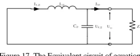
And when S<0, the equivalent circuit is given in the Figure 17 and the state equations is the equation (2).
Figure 17. The Equivalent circuit of equation (2)
But, from the equation (1) and equation (2), the relation between is a four-order polynomial. There must be oscillations and the exchange of energy between Lf1, Lf2,
Cf1 and Cf2. In order to make the system more stabilized,
some small buffer circuits are needed to be connected in parallel with the MOSFETs.
Figure 18 is the simulation system based on the Simulink platform.
Figure 18. The Simulation System
A additional 1 Ω resistance is series connected with the Cf1 to help the system more stabilized, too.
The figure19 is the VSC controller. The sample frequency and the values of Lf1, Lf2, Cf1 and Cf2 must be
select carefully or the system would be unstable.
Figure 19. The VSC Controller
(a)
(b)
The result of simulation is given in the Figure 20. The Figure 20(a) is the waveform of Us and Uo and the Figure 20(b) is the relation between Us and Uo.
In the Figure 20 (b), the waveform is almost a straight line. There is a small oscillation near the two peaks and a small phase shift near the zero point.
The Figure 21 is the switch control pulses. From the small window in the top right corner, it can be seen that the switch periods is not unchanged.
Compared to the PID controller, the switch frequency of VSC can be controlled dynamically. When the input voltage is high the MOSFET switched faster, and on the contrary, when the input voltage is low the MOSFET switched slower. This function can reduce unnecessary switching loss while it is maintaining the same error level.
In the same time, the VSC has faster response speed. When the system left the switching plane, the VSC controller can draw the system back to the switching plane as fast as it can. However, the problems about stability are more complex to analyze and control.
The Figure 22 is shown the waveform of switching function S. It is also the error between UO and Utarget.
From the waveform of S, the VSC controller can control the system running near the switching plane almost all time but the small region closing the zero. The reason is the Us can be ignored when the input closing zero. Then the two structures become similar and the VSC controller can’t work again. The same problem is also existed in the traditional control for Buck and Buck-Boost topologies.
Figure 21. Switch Control Pulses in VSC
Figure 22. The Waveform of S
The energy changing of Lf1, Lf2, Cf1 and Cf2 lags the changing of input Us. How to through the zero point smoothly is a main point of the VSC strategy which will need more research.
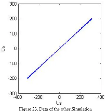
In fact, there always are small oscillation depended on the instantaneous value of the voltage source. When the instantaneous value of input voltage is small the amplitude of oscillations is also small and when the instantaneous value is larger the amplitude of oscillation is also larger. This is way the oscillation near the two peaks is more unambiguous. It can be seen more clearly in the simulation based on the other group parameters.
The Figure 23 is the relation between US and UO of the other grout simulation parameters.
Figure 23. Data of the other Simulation
The Figure 24 is the error based on the second group simulation parameter.
Compared to the Figure 22, the VSC controller has no help for the errors while the input Us run through the zero point.
Same as the PID controller, the VSC controller can also work well while the input voltage containing 11-order harmonic.
Figure 24. The Error / Switching Function S
The Figure 25 is the voltage waves of UO and US on
the condition of 11-order harmonic interference.
Figure 25. Voltage Waves for 11-Order harmonic Interference
V. CONCLUSION
The simulation results of different control strategies based on the Simulink platform for Buck-Type converter are given in this paper. The comparing and analysis of these results shows that the VSC controller is more effective and can almost eliminate the phase shift between input and output. In the other hand, the switch period can be regulated following the error. So a balance between reducing switching loss and improving quality of output and a smaller response time can be gained. At the same time, the VSC controller can filter the high order harmonic contained in AC source effectively. But how to through the zero point smoothly is still a main point of the VSC strategy which need more research.
REFERENCES
[1] Petry, C.A., J.C. Fagundes, and I. Barbi. New Direct Ac-Ac Converters Using Switching Modules Solving the Commutation Problem. in Industrial Electronics, 2006 IEEE International Symposium on. 2006.
[2] Jin, N., et al. Analysis and control of Buck-Boost Chopper type AC voltage regulator. in Power Electronics and Motion Control Conference, 2009. IPEMC '09. IEEE 6th International. 2009.
[3] Daolian, C., Novel Current-Mode AC/AC Converters With High-Frequency AC Link. Industrial Electronics, IEEE Transactions on, 2008. 55(1): p. 30-37.
[4] Difei, T. and L. Lei. Analysis and simulation of push-pull three level AC/AC converter with high frequency
link. in Industrial Electronics and Applications, 2009. ICIEA 2009. 4th IEEE Conference on. 2009.
[5] Minh-Khai, N., J. Young-Gook, and L. Young-Cheol, Single-Phase AC-AC Converter Based on Quasi-Z-Source Topology. Power Electronics, IEEE Transactions on, 2010. 25(8): p. 2200-2210.
[6] Jin, N., H.-j. Tang, and G.-z. Cui. Adaptive neuron PID control of Buck type AC chopper voltage regulator. in Bio-Inspired Computing, 2009. BIC-TA '09. Fourth International Conference on. 2009.
[7] Fang Lin, L. and Y. Hong. DC-Modulated Power Factor Correction AC/AC Converters. in Industrial Electronics and Applications, 2007. ICIEA 2007. 2nd IEEE Conference on. 2007.
[8] Vazquez, N., et al. A fast ac voltage regulator. in Power Electronics Congress, 2008. CIEP 2008. 11th IEEE International. 2008.
[9] Middlebrook R, C., S., A general unified approach to modeling switching-converter power statges. Journal of Electronics, 1977. 42(6): p. 521-550.
[10] Lee, Y.S., A Systematic and Unified Approach to Modeling Switches in Switch-Mode Power Supplies. Industrial Electronics, IEEE Transactions on, 1985. IE-32(4): p. 445-448.
[11] Sira-Ramirez, H., Sliding motions in bilinear switched networks. Circuits and Systems, IEEE Transactions on, 1987. 34(8): p. 919-933.
[12] Wong, R.C., H.A. Owen, and T.G. Wilson, An Efficient Algorithm for the Time-Domain Simulation of Regulated Energy-Storage DC-to-DC Converters. Power Electronics, IEEE Transactions on, 1987. PE-2(2): p. 154-168.
[13] Sira-Ramirez, H., A geometric approach to pulse-width modulated control in nonlinear dynamical systems. Automatic Control, IEEE Transactions on, 1989. 34(2): p. 184-187.
[14] Sira-Ramirez, H.I.-S., M., Exact linearization in switched-mode DC-to-DC power converters. International Journal of Control, 1989. Vol.50(No.2): p. 511-524.
[15] Smedley, K.M. and S. Cuk. One-cycle control of switching converters. in Power Electronics Specialists Conference, 1991. PESC '91 Record., 22nd Annual IEEE. 1991.
[16] Sira-Ramirez, H. and M. Rios-Bolivar, Sliding mode control of DC-to-DC power converters via extended linearization. Circuits and Systems I: Fundamental Theory and Applications, IEEE Transactions on, 1994. 41(10): p. 652-661.
[17] Czarkowski, D., L.R. Pujara, and M.K. Kazimierczuk, Robust stability of state-feedback control of PWM DC-DC push-pull converter. Industrial Electronics, IEEE Transactions on, 1995. 42(1): p. 108-111.
[18] Sira-Ramirez, H., et al. A sliding mode controller-observer for DC-to-DC power converters: a passivity approach. in Decision and Control, 1995., Proceedings of the 34th IEEE Conference on. 1995.
[19] Erickson R W, M.D., Fundamentals of Power Electronics. 2nd Edition. Kluwer Academic Publishers, 2001.
[20] Cheng, K.W.E., Storage energy for classical switched mode power converters. Electric Power Applications, IEE Proceedings -, 2003. 150(4): p. 439-446.