Volume 11, Number 1, pp. 81–97. http://www.scpe.org c 2010 SCPE
OSYRIS: A NATURE INSPIRED WORKFLOW ENGINE FOR SERVICE ORIENTED
ENVIRONMENTS∗
MARC EDUARD FRˆINCU†AND DANA PETCU†
Abstract. We present a nature-inspired rule-based workflow platform capable of self adaptation by following an event-condition-action approach and by integrating a dynamic resource selection relying on rule based scheduling heuristics. A language for workflows that is simple and easy to understand is introduced. The language also supports task semantics and ontology definition.
Key words: nature inspired workflow, workflow language, automatic workflow generation, scheduling mechanism, workflow management
1. Introduction. Nature has proven to be a good source of inspiration for computer software paradigms within work spreading from membrane computing [35], cellular-automata [37] and genetic algorithms [9] to neural networks [5]. However little attention, most of which is purely theoretical with no concrete validation of the model [32, 33], has been given to creating a nature inspired workflow language and engine. Nature provides excellent examples of orchestrating evolution rules and we need not go further than the chemical reaction laws to find such ones. In a chemical reaction, solutions are usually transformed into others by using substitution, synthesis, chemical decomposition, or other methods [25]. Yet the reactions only occur when there exist the right reactants which can be in turn the result of other reactions. When binding together these reactions what we obtain is a chain reaction. Chain reactions are the counterparts of workflows in computer science. An example of such a chain reaction is the photochemical reaction between hydrogen and chlorine where the chlorine atoms react with hydrogen until other reactions consume the remaining free atoms of chlorine or hydrogen.
From a computer perspective the advantages of such an approach include implicit parallelism and non-deterministic reaction order which allow: faster rule execution; decentralized approach as the reactions can occur without the supervision of a central entity; less workflow constructs (such as the parallel construct); simpler syntax (only the reaction rule is required); possibility of expressing self-adaptivity to failures as rules etc. Together with a Distributed Environment (DE) where each task would be executed on a different machine this approach could provide the basis for a self-adaptive and dynamic workflow platform in which the engine behaves as a natural entity.
This paper describes a workflow platform, called OSyRIS (Orchestration System using a Rule based Infer-ence Solution) and a concrete usage example. Sections 2 and 3 will present a brief state of art on workflow engines and respectively a formalisation based on a chemical model. The OSyRIS design (detailed in Sec-tion 4.1) is founded on the concepts described in [32, 33] which provided the idea of creating workflows based on chemical reactions. An implementation called SiLK (Simple Language for worKflows) of the chemical formal-ism presented in the previous citations is also presented in Section 4.2. The platform is adapted to cope with DE such as Grids by introducing support for Web Services (WS). It offers self-adaptivity to resource changes (Sections 4.4 and 4.5) and allows automatic workflow generation (Section 4.3) based on a given goal, some task semantics and an initial rule base. Additional helper modules such as a visual workflow designer (Section 4.6) and administrator (Section 4.7) are also presented. The platform is validated against a real case scenario (Sec-tion 5) which requires the orchestra(Sec-tion of multiple image processing opera(Sec-tions for manipulating large satellite images.
2. Related Work and Issues Regarding Workflows. A lot of work has been accomplished towards achieving self-adapting WS orchestration and many elaborated solutions exist in the form of advanced languages [4, 23, 40, 43], complex workflow engines [1, 16, 31, 39, 41], graphical tools [42] or workflow task planners [16]. Few authors have recently concentrated thier efforts [3, 7, 13, 27] towards the dynamic enactment of scientific workflows including automatic error handling; the runtime resource allocation and task planning; or the adaptivity to changes in workflow logic and system characteristics.
∗This work has been partially supported by the European Space Agency PECS Contract no. 98061 GiSHEO: On Demand Grid
Services for High Education and Training in Earth Observation.
†West University Of Timisoara, Blvd. Vasile Parvan No 4, 300223, Romania ({mfrincu, petcu}@info.uvt.ro)
A lot of recent work focuses on workflow solutions aiming at improving classic solutions like Condor [39], YAWL [40], Pegasus [16], Taverna [34], Triana [15] or ActiveBPEL [1]. A new trend which relies on Event-Condition-Action (ECA) driven solutions has emerged in relationship with AgentWork [29], VIDRE [31] FARAO [41] or Drools Flow [6].
ECA based engines allow an alternative declarative approach by introducing [41]: languages having intu-itive formal semantics through the use of a limited set of primitives, direct support for business and science policies,flexibilityby allowing self-adaptation through the use of rules which permit alternative execution paths, adaptability through the insertion and/or retraction of rules and reusability thanks to their property of being isolated from the process context. Although non-ECA approaches can also be modified to cope with these advantages, ECA solutions are preferred due to their concept of rule based programming. Non ECA engines usually have limited predefined and built-in control constructs such as sequence, parallel, split, join, loops or events. In contrast, ECA engines have one single built-in control construct, namely the inference rule, all the other constructs naturally deriving from it. ECA approaches also offer other advantages like separation of logic (rules) from data (objects), declarative programming, scalability or centralization of knowledge, etc.
All the existing workflow engines deal with the same problems including changes in data integrity issues, error handling, and resource availability changes.
Data integrity issues can be solved either by ensuring proper service selection or by allowing user interven-tion. Workflow engines like ActiveBPEL, Condor or gEclipse do not have integrated modules to cope with the latter. These engines require a redeployment of the workflow in order to allow user intervention. Still work on this topic exists and our paper [11] presents a solution in which ActiveBPEL workflow tasks are enhanced with pause/resume/cancel operations. Triana is an example which allows to stop/resume/reset workflows and change input parameters to tasks from the interface.
Proper service selection can also be achieved in several ways: by using Hoare semantics [26] in order to automatically check if a workflow can produce the desired outcome by its actual implementation and to synthesize a workflow implementation; by using ontologies [4, 14] to describe tasks and their relationships as well as the compositional rules; by using an AI planner [44]; or, given a desired goal and some task semantics, by using a backward chaining mechanism for selecting the proper task chaining as it will be detailed in this paper. Error handling is of importance too. Workflow errors can be caused either by logic failures (e.g. wrong workflow design) or physical failures (e.g. network or resource failures). As far as the latter are concerned Taverna halts the execution of the entire workflow in case a service invocation fails [17]; ActiveBPEL provides a try-catch mechanism for handling invocation exceptions; Triana also has an in-built mechanism for preventing the system crash in case of workflow errors; YAWL uses ripple down rules [3] in order to cope with execution errors; FARAO relies on a monitor-plan-act cycle based on the Adaptive Service Oriented Architecture [24] which allows semi-autonomously service adaptation; and Pegasus handles errors either by rescheduling a crashed task or by creating a rescue DAG. Paper [26] presents a solution in which engine failures are dealt with by spliting the workflow into several smaller ones, part of the initial rule base.
Some workflow engines such as YAWL [3], Taverna [34], Triana [15] or ActiveBPEL [13] allow runtime ser-vice selection. This is highly important in case of resource failures. However in the case of the previously listed examples, neither this step is separated from the core of the engine nor this functionality is easily achieved [27]. Unlike these workflow engines, the Pegasus system [16] does allow the integration of custom selection or schedul-ing policies, which makes task execution much more efficient. We argue that schedulschedul-ing policies are essential since they can cope with resource, network or task failures and can augment the workflow execution time by periodical task reassignments. These reassignments are necessary because of the possible delays in task execu-tion inflicted by local schedulers running on the resource where the services are located on. The same problem arises in the ECA driven engines which deal mostly with task and data dependencies and tend to ignore the planning aspect [6, 29].
Section 3 will show that nature inspired workflow paradigms have the advantage of offering a non-determi-nistic and inherently concurrent environment where no serialization is imposed.
Among the few formalisations of a nature inspired workflow enactment we notice the work of Banˆatre [7] and N´emeth [32, 33]. Their work relies on a chemical metaphor based on the Gamma (General Abstract Model for Multiset Manipulation) [8] language. This concept follows the chemical model in which there is no concept of centralization, serialization, ordering and the computations are accomplished in a non-deterministic way.
γ-calculus is a formal definition of the Gamma paradigm and the fundamental structure is represented by the multisetM. Terms (or molecules) are represented by: variablesx,γabstractions (reactive molecules)γhxi⌊C⌋.M
(whereC is the condition required for reducing the abstraction), multisetsMi and solutionshMi.
The reduction of the γ-abstraction is performed by the reactions inside a solution hMi. The reduction simply means capturing molecules that match given parameters (variables) and replace them with instantiated values inside the specified solution. More specifically γhxi⌊C⌋.M means replacing every occurrence of x in solutionhxibyM ifC.
Usingγ-calculus, a task execution can be modeled as:
γhTj :x, ωTi.(γhid:r, Res, ωResi.execute Tiusing x on r) (3.1)
Based on the previously described Gamma formalism we introduce the following workflow notation:
W= (V, µ, M1, . . . , Mn,(R1, ρ1), . . . ,(Rn, ρn), s0) (3.2)
where: V is the set of tasks (or molecules), µ represents the solution structure containing all the other n solutions,Mi, i= 1, n, stand for the multisets overV belonging to then solutions,Ri symbolizes the reactive
molecules (or simply the reactions),ρi, i= 1, nrepresent priorities among the reactions ands0is the outermost
solution.
Given the previous workflow notation (Relation 3.2) we easily notice that the definition closely resembles that of the P-System [46]. The sole major difference is that of using chemical solutions instead of cellular membranes.
Although Relation 3.1 offers a representation for task execution within chemical solutions it is difficult to implement an easy to use computer language based on it. In addition we can further refine the representation by modeling the concept of conditional execution through a function similar to the one presented in Relation 3.3:
ǫ:M∗
i C,ρi
−−−→Mi (3.3)
whereM∗
i =MiS{TI}and taskTI is an initialization task required by the engine in order to start the workflow
execution by creating the instance of the first actual task.
Using Relation 3.3, workflows can also be defined as transitions between different tasks, with ǫ being a transition function.
Having a set of reactions is however not sufficient as we could have an incomplete chaining which would not lead to the desired outcome. As a consequence we define the notion ofconsistent workflow as: a workflow where the chain of reaction leading the initial input to its outcome (goal) is unbroken. Any workflow not obeying the previous rule is in our assumptioninconsistent.
Proposition 3.1. Given a consistent workflow, the previously definedǫ function is surjective.
Proof. Obvious as given a consistent workflow each task part of the co-domainMi has at least one
prede-cessor task from the domainM∗
i.
The previous proposition is useful for both validating workflows using a backwards chaining method and generating them starting from a given goal. Section 4.3 will detail these aspects.
Given a solution which can contain several others, reactions occur in a parallel and non-deterministic way. They also proceed automatically to the next surrounding solution once all reactions within the current one have finished.
Section 4.2 will expose a rule based workflow language built on top of the previously outlined model and introduce a simple notation based on theǫfunction that follows on an ECA approach. The proposed notation for task execution is simpler and thus more user friendly than the Gamma formalism introduced by N´emeth [32, 33].
as well as their inter-connections. Its modular design allows each major component (engine, visual designer, workflow generator and administrator) to work independently from each other. The following sections will detail each component.
Fig. 4.1.Architecture of the OSyRIS platform
The OSyRIS (Orchestration System using a Rule based Inference Solution) workflow engine was designed in order to provide a solid and reliable workflow platform for complex image processing requests. It has proven to be useful in a wider range of problems than the initial scope of binding together image processing operators, examples including modeling scheduling algorithms as detailed in Section 4.5. The platform also had to be capable of adapting to resource and network failures or changes by allowing task reallocation to the best available service and permitting workflow restarts from previous failure points. Task reallocation is essential as it deals with large images up to several gigabytes each. Taking advantage of both the ECA based approaches regarding task composition [6, 29, 31, 41] and the nature inspired workflow formalisation (Section 3), a simple and yet expressive language called SiLK has been developed to cope with the problem of mixing together into a workflow different image processing operators. Details about the language capabilities will be further explained in Section 4.2.
ECA allows the separation of workflow logic from the workflow engine without having to manage with the complexity of workflow constructs. Engines following the ECA approach only have to understand a single construct that models a rule-based transition from several tasks to others. The transition is usually triggered by some events and conditions. Starting from this construct a wide range of classic constructs can be built without modifying the engine itself. Furthermore this approach allows to easily modify at runtime the workflow structure by inserting and/or retracting execution rules.
What differentiates OSyRIS from other solutions [1, 6, 16, 29] is the nature inspired approach and the integration of a scheduling module based on the same SiLK language and governed by the same engine. This mechanism allows for workflow tasks to be assigned using a chemical paradigm in which multiple scheduling heuristics are chosen at runtime based on the conditions existing at that moment for triggering certain rules. Further details on this topic will be addressed in Section 4.4.
4.1. The OSyRIS Engine. The OSyRIS engine (see Figure 4.1) is built on top of the Drools Expert [6] inference engine which uses a modified object oriented version of the RETE [18] algorithm for rule matching. The engine can be either embedded inside any Java application or exposed as a WS which can be later invoked by any SOAP enabled client. It also allows users to submit SiLK written workflows which are then translated into DROOLS rules. Any syntactic errors are handled at this point.
workflow), finding the output of a particular workflow task, retrieving the workflow (or task) status. Each workflow is uniquely identified by an ID which can be used when an asynchronous workflow execution is considered. An asynchronous execution means that the workflow is either started in a different thread or exposed as a WS, each of them periodically queried for information. Besides these features users can implement their own custom extensions according to the application needs. The second one, called Executor, handles specific application details such as discovering proper resources for task execution and communication between services and the engine. Once they are implemented the OSyRIS engine handles the actual rule execution.
An issue which cannot be neglected and which all workflow engines have to deal with is represented by the inter-task communication. In our case the OSyRIS engine offers two kinds of communication formats: SOAP based and message queue based. SOAP is predominantly used in cases where the engine is exposed as a WS while a message queue service is a preferable choice when the engine is embedded inside Java applications. OSyRIS uses Apache ActiveMQ [38], an implementation of the Java Message Service 1.1 [2] specification, as message queue system and provides an interface for users to extend by adding their own functionality. The communication is handled by theExecutor class which is responsible for sending requests and receiving answers from services running tasks in a user specified format.
When using an ECA approach, the output result of a workflow represents the output of the lastly executed task after a chain of rules has been fired. This task could be different from the actual final task when inconsistent workflows (see Section 3) are created or incompatible tasks are joined together. Task incompatibility means that Right Hand Side (RHS) tasks linked to Left Hand Side (LHS) tasks cannot use the output of the latter ones as input. For instance an image processing task receiving as input an image will not be compatible with a task producing a number when the former needs to send its output to the latter. This problem can also occur due to unavailable specialized services for solving RHS tasks and can be avoided at design time, by applying model checking or by ensuring that a user using a visual tool cannot generate such incompatibilities. Runtime checks can also be produced but they will mainly lead to exceptions which halt the workflow execution in case no other valid rule can be triggered.
Much of the workflow information is stored into a database (see Figure 4.1) for later query and reports. This information includes task execution times, input and output data for each task, number of instances for each task, execution status (both for workflows and tasks) and used resources. The stored information can be later on used either for creating statistics on resource usage and task characteristics or for restarting previously failed workflows. The database information is partly used by the Workflow Manager described in Section 4.7.
The execution path is also stored in a log. This log can be used for handling events such as workflow execution failures or when taking scheduling decisions by the task scheduling component discussed in Section 4.4.
4.2. The SiLK Language. Workflow languages need not be verbose but have a simple syntax so that inessential syntax overhead should be avoided and be expressive enough to be able to cope with a wide range of constructs and situations without needing to introduce new constructs. The Simple Language for worKflows (SiLK) is the result of several design attempts involving both XML [43] and rule based workflow languages [6] as means of expressing OSyRIS workflows. The goal was to develop a simplified language for handling image processing requests and yet not lose its applicability to other fields.
XML based approaches [40, 43] ignore syntax simplicity as they add too much unnecessary information and offer a limited set of control constructs making them inherently verbose. Therefore it is the user who has to modify both the language and the parser whenever new constructs are required. As an alternative we also studied ECA languages such as the HOCL language [32] whose syntax we found too complicated for actual user oriented usage and more suitable for formalism description.
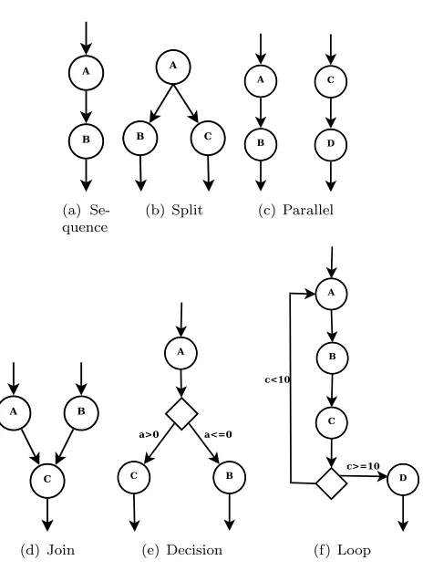
SiLK was first described in an incipient form in our paper [19]. It offers elementary constructs such as sequence,parallel,split, join,decision orloop (see Figure 4.2).
(a) Se-quence
(b) Split (c) Parallel
(d) Join (e) Decision (f) Loop
Fig. 4.2.Several types of elementary workflow constructs
The following code fragment shows how we can define a task with one input initialized with a predefined value, one output port and one meta-attribute:
A := [i1:input="image.jpg", o1:output, "processing"="grayscale"];
The value is admitted for storage inside the meta-attributes or as initial value for a certain port. It can contain either a plain text to be sent directly to the service or a pointer (ID) to a database (table, element, etc.) or file (line etc.) which is interpreted by the custom Executor class. The value of the pointer is either forwarded to the WS for handling or stored in a database.
Another use for meta-attributes is to define and use task semantics and ontologies. Ontologies require users to define a set of concepts or tasks in our case, attributes related with them and relationships between them. SiLK allows to easily define task semantics or ontologies by using task attributes, meta-attributes, and task relationships through the use of inference rules (as it will be detailed in what follows).
A SiLK file represents not only a workflow formalization but also an actual task ontology. In addition to this definition of relationships users can also embed them within task definitions as meta-attributes. Meta-attributes also allow users to define task relationships without using inference rules. This approach is however not safe as it can lead to problems such as inconsistent workflows due to user errors. As an alternative a backwards chaining generating module will be detailed in Section 4.3.
Within a SiLK file task definitions must precede rules which are checked by the OSyRIS engine for validity against already known tasks.
SiLK rules are defined based on theǫfunction defined in Relation 3.3. The new notation allows us to express transitions from one multiset of tasks to another as follows: LHS -> RHS|condition, saliencesyntax where thecondition and thesalience are optional. The RHS and LHS are made up of tasks separated bycommas and linked with each other through the use of variables attached to ports:
A[a=o1], B[b=o1] -> C[i1=a#i2=b]
case the bindings are separated by the # character. If more than one task exists in the RHS then each of them gets executed in parallel by the OSyRIS engine inside a separate thread.
Any RHS task linked to multiple variables must have every variable linked to a different input port. Gen-erally it can be said that it is prohibited to have multiple incoming edges attached to a single input port. This restriction does not stand in case of LHS tasks where we can have the same output port linked to more than one RHS input ports as it happens for asplit construct.
As previously mentioned a rule can have optionalcondition andsalience. The salience is represented by an integer number (negative or positive) and translates the importance of the rule with large values making the rules more important and increasing their chance of execution in case multiple rules are ready for firing at the same time. The condition can be any logical statement which uses integer, floating point or string operands. The following example shows a set of rules which mimic a loop construct by using conditions:
A[a=o1] -> B[i1=a]; B[b=o1] -> C[i1=b];
C[c=o1] -> A[i1=c] | c < 10; C[c=o1] -> D[i1=c] | c >= 10;
The loop construct can also be viewed as a chain of reactions where we eventually end up with the initial reactant which would trigger the entire chain all over again.
Inside rules users can also manipulate task behaviours. More precisely the behaviour of a LHS task refers to whether itsinstance gets consumed or not after triggering a rule or to how manyinstances get created when a RHS task completes its execution. The default behaviour is consume=true for LHS tasks and instances=1 for RHS ones. The following example shows how we can tell the engine not to consume the LHS task and to create 5 instances of the resulting RHS task:
A[a=o1#consume=false] -> C[i1=a#instances=5];
Task instances are nothing else than a programming construct to represent the notion of multisets. Due to the fact that by using rules we allow for implicit parallelism by introducing the concept of task instances we can also create explicit rule sequencing. As an example we can consider the two rules where LHS taskAhas only one initial instance and each of them produces another instance of taskA. In this case the rules cannot fire simultaneously and one of them needs to wait for the other to produce the necessary task instance. When creating new task instances these are added to the already existing ones. Considering two rules which create 2 respectively 3 instances of the same task Awith no instance of it being consumed in the process we end up with 5 instances of the same task. The number of task instances can also be set during task definition by using a special meta-attribute calledinstances which receives a numerical value. The default behaviour is of creating zero instances during task definition. Task instances also allow for users to specify loop constructs with a finite number of steps such as theforin Java. Thus the exit condition is marked by the number of task instances which continue to trigger rules:
# Rule 1:
A[a=o1] -> B[i1=a#instances=10], C[i1=a]; # Rule 2:
C[c=o1], B -> C[i1=c];
Moreover task instances are also useful when considering scheduling heuristics based on task replication as it allows multiple instances of the same task to execute on different services. For instance the following lines of code show how 5 instances of the same taskB are created and only a single one is being used afterwards for executing taskC:
A[a=o1] -> B[i1=a#instances=5]; B[b=o1] -> C[i1=b];
The correct destruction of the remaining four tasks needs however to be dealt with from inside the custom Executor class.
Task instances also allow to easily manipulate workflow related operations such as pause, resume, restart and abort. This is primarily due to the fact that task instances are the main rule triggers in OSyRIS.
except the timer can be constructed using variations of rules containing one or more input/output ports and conditions.
Timersare not explicitly defined in the SiLK language but can be simulated by using so called idle services which receive as argument a numerical constant representing time in milliseconds and return after that particular time period.
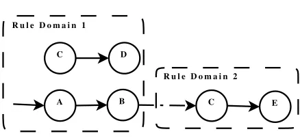
When dealing with reactions within a solution we can also assume that we have more than one sub-solution contained in the main solution. Paper [7] details how reactions within such a complex solution occur. Starting from a sub-solution, reactions consume the task instances inside it and only then they proceed to the parent solutions triggering other reactions and so forth until all possible reactions have triggered. SiLK offers the possibility to mimic this behaviour by allowing users to specify rule domains. Each rule domain is identified by an integer number and a rule is considered by default to belong to the domain 0, unless it is explicitly attached to one. At any given time only one domain can be active and only the rules inside it can execute. However users can define transition rules where some LHS tasks belong to a domain different from the other tasks. In this case, after firing the engine, the platform will automatically select the new domain (to which the RHS tasks belong to) as the active one.
Figure 4.3 shows three rules belonging to a workflow. The first two belong to domain 1 and the third one belongs to domain 2. Assuming that the first rule in domain 1 can fire it will determine the activation of domain 2 and the subsequent execution of rule 3, and not rule 2 which belongs to domain 1. The next code fragment shows the representation in SiLK of the example:
# Rule 1 in domain 1:
1 : A[a=o1] -> B[i1=a], 2:C[i1=a]; # Rule 2 in domain 1:
1 : C[c=o1] -> D[i1=c]; # Rule 3 in domain 2: 2 : C[c=o1] -> E[i1=c];
C D
E C
B A
R u l e D o m a i n 1
R u l e D o m a i n 2
Fig. 4.3.Switching between rule domains
As it can be noticed from the previous example, SiLK rule domains allow constructing rule sets without inducing a strict hierarchy. Thus SiLK domains are more complex than the solutions introduced by [7] (see Section 3) as they allow for the workflow to switch freely between multiple sets of rules when necessary. On the other hand solutions allow transitions only when their reactions are no longer active.
4.3. Automatic Workflow Generator. There are cases when the user does not know or simply does not have the time to design the chain of rules making the desired workflow. In this case it is mandatory to have the possibility to automatically generate the workflow given its goal. OSyRIS offers theWorkflowExtractor class as part of the Workflow Generator module (see Figure 4.1) for cases where automatic generation is required. There are three basic approaches to this problem: using task semantic information; relying exclusively on rules; mixing the last two.
in Section 4. The format serves to identify corresponding services through an UDDI, based on the functions they expose. For example:
A0:=[o1:output="image_normal", ‘‘instances"="1"]; A:=[i2:input, o1:output, "processing"="image_red
extract-band(band,image_normal)", ‘‘argument-list"="<band=red>"];
B:=[i2:input, o1:output, "processing"="image_infrared extract-band(band,image_normal)",
‘‘argument-list"="<band=infrared>"];
C:=[i1:input, i2:input, o1:output, "processing"= ‘‘image_ndvi compute-ndvi(image_red,
image_infrared)"];
In the previous case the information details the processing each task is going to do, its output type and the arguments of the call. Ports have indices corresponding to the position of the function arguments (i.e input port i2 is linked to the second argument of the extract-band function calledimage) and optionally arguments can have initial default values as specified by the argument-list meta-attribute. It can be also noted that we have chosen a C-like function prototype naming for describing task processing. Starting from the task meta-attributes description the backwards chaining creates corresponding workflows. In order to make this happen the engine needs to be able to parse and interpret relevant meta-attribute information (it is up to the user to implement this custom handler). One solution is found corresponding to the simple example previously described:
A0[a=o1] -> A[i2=a], B[i2=a]; A[a=o1], B[b=o1] -> C[i1=a#i2=b];
The second approach is relying solely on rules described in the rule base. While this approach is somewhat easier as the rules already offer a precedence relationship between tasks, it could provide faulty workflows as the rule base extends by receiving more and more rules which could conflict with older existing ones.
The last approach represented by a mixture of the previous two is currently under consideration for future implementation.
When applying the two approaches described above, it is necessary to exist an initial rule base containing all the allowed relations between tasks based on either rules or meta-attributes. From this rule base can be created a set of disjoint graphs that are essential when obtaining the list of relevant workflows for the given goal. The backward chaining phase is generated by using a depth first algorithm. The workflow execution phase begins with the user choosing the desired goal from a list of available tasks extracted from the RHS tasks inside the rule base. Then the final rules are extracted from the rule base using backwards chaining. After several workflow solutions have been generated, the user can choose one of them depending on available input and then execute it by using the OSyRIS engine.
As an example we can consider the following code that shows a simple rule base:
A:=[i1:input="initial input A", o1:output, "proc"="operation-A"];
B:=[i1:input, o1:output, "proc"="operation-B"]; C:=[i1:input, o1:output, "proc"="operation-C"]; D:=[i1:input, o1:output, "proc"="operation-D"]; E:=[i1:input, o1:output, "proc"="operation-E"]; M:=[i1:input, o1:output, "proc"="operation-M"]; F:=[i1:input, i2:input, o1:output,
"proc"="operation-F"];
P:=[i1:input="initial input P", o1:output, "proc"="operation-P"];
A[a=o1] -> B[i1=a],C[i1=a]; B[b=o1] -> D[i1=b];
D[d=o1] -> E[i1=d]; C[c=o1] -> E[i1=c];
M[m=o1] -> F[i1=m]; P[p=o1] -> M[i1=p];
This rule base can be represented as the graph seen in Figure 4.4.
C A
B D E
F M
P
Fig. 4.4.Rule Base Chaining Example
Given the desired output taskF the following two possible workflows are automatically created:
M:=[i1:input, o1:output, "proc"="operation-M"]; F:=[i1:input, i2:input, o1:output,
"proc"="operation-F"];
P:=[i1:input="initial input P", o1:output, "proc"="operation-P"];
M[m=o1] -> F[i1=m]; P[p=o1] -> M[i1=p];
and respectively:
A:=[i1:input="initial input A", o1:output, "proc"="operation-A"];
B:=[i1:input, o1:output, "proc"="operation-B"]; C:=[i1:input, o1:output, "proc"="operation-C"]; D:=[i1:input, o1:output, "proc"="operation-D"]; E:=[i1:input, o1:output, "proc"="operation-E"];
A[a=o1] -> B[i1=a],C[i1=a]; B[b=o1] -> D[i1=b];
D[d=o1] -> E[i1=d]; C[c=o1] -> E[i1=c];
E[e=o1],C[c=o1] -> F[i1=e#i2=c];
It can be noticed that there have not been not produced two different workflows one for the rule chain A
→C→ F and another forA →B→D →E→ F as task F is produced by the join of tasksE andC. Backwards chaining is possible as the ǫ function (see Relation 3.3) is right-invertible, a property which follows from its surjectivity (see Proposition 3.1). Thus a rule chain could be determined, if existing, starting from the desired goal.
The workflow generator produces merely abstract workflows [32] where only the logic of the problem is expressed without attaching any means of solving it. In order to accomplish the latter, a mapping of tasks on services is required. This action produces a concrete workflow which can then be executed by the engine. In order to obtain full dynamism and autonomy the conversion between abstract and concrete workflows must take place during runtime by means of a resource selection and scheduling mechanism similar to the one presented in Section 4.4 and Section 4.5.
the best suitable choice for the situation at hand. The task selection API is implemented inside the Scheduling module as seen in Figure 4.1.
The first method involves the usage of an externalResource Selector. This approach relies on the fact that each OSyRIS task is exposed by an external WS. An intermediate Broker Service added between the actual service and the engine will be responsible for dispatching tasks coming from the engine to appropriate resources. Scheduling capability can be optionally integrated inside the broker.
The second method is to implement additional functionality and link it directly with the custom built Executor class. In this case the scheduling passed from the Broker Service to an additional class called by the application specificExecutor class. After taking a decision theExecutor will send the task directly to the WS without using any intermediate brokers.
The last one enables adding resource selection decisions inside rules. When using it the scheduling decision will be inserted directly inside the rules. Two different approaches can be also considered in this case. The first one requires modifying theSiLK2Rulesclass responsible for translating the SiLK rules into DROOLS rules and using theWFResource collection which contains a list of available services. In this case a distinct rule condition must be added inside each of the OSyRIS generated DROOLS rules. This condition will enclose all the required scheduling decisions and will return one or more potential services where the task can be safely executed. The second approach implies using a separate service similar to theBroker Service. The sole purpose of the service is to deal with scheduling other tasks. In addition the service will be treated as normal task that is attached to the LHS of each rule. Its output consisting of a set of available services will be transmitted as input to all the RHS tasks. The service itself relies on an OSyRIS engine instance where rules represent scheduling heuristics (see Section 4.5).
Besides service selection, the service discovery plays an important role too as it enables the engine to have a pool of services to choose from. Similar to Taverna [34], services can be discovered using various techniques such as UDDIs, direct URL input, previous workflow introspection, semantic searches, etc. OSyRIS uses by default UDDIs but extendible plug-ins can be easily integrated to cope with the rest of the choices.
4.5. Scheduling mechanism. Scheduling is closely related to resource discovering and usually involves assigning tasks to resources using certain rules. OSyRIS offers these as a single module (see Figure 4.1). Following the nature inspired approach OSyRIS offers the possibility to express scheduling heuristics in the SiLK language. In this way users can define their own scheduling heuristics by adding them to the heuristics rule base. Each such scheduling heuristics could be located in its own SiLK domain. Following this approach resource selection can be augmented by selecting heuristics dynamically at runtime based on known criteria such as dimension of dependent data, network and resource heterogeneity, etc.
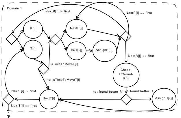
Resource selection is essential as it is known [10, 12, 28] that, given the grid characteristics, scheduling heuristics perform differently in dissimilar scheduling scenarios. Based on previous work and knowledge on the network, resource and task characteristics, the best fitted scheduling heuristics could be selected during runtime from a general rule base by adding conditions for triggering the reactions inside the corresponding solution. To achieve this we must first define the tasks and rules each scheduling heuristics has. Figure 4.5 shows such a decomposition for the case of the DMECT heuristics [21].
The DMECT scheduling heuristics is represented by the following fragment of code:
while (exist tasks in T_list) do { foreach (task in T_list) do
if (task is new) then
assign task to random queue; foreach (queue in queue_list) do
if (queue not sorted
sort tasks in current queue descending by TWT; repeat {
foreach (queue in queue_list) do foreach (task in current queue) do
if (task exceeds time constraint) then { find new queue based on condition; find position to insert such that tasks
place task on new queue at the found position; }
} until (not task has been moved) }
Domain 1
NextR[j]
AssignR[i,j] R[j]
T[i]
NextT[i]
isTimeToMoveT[i]
not isTimeToMoveT[i]
N e x t T [ i ] ! = f i r s t
N e x t T [ i ] = = f i r s t
N e x t R [ j ] = = f i r s t N e x t R [ j ] ! = f i r s t N e x t R [ j ] = = f i r s t
Check-
External-R[i]
found better R not found better R
AssignR[i,j] ECT[i,j]
Fig. 4.5. DMECT workflow
Briefly, DMECT simply checks for each task if a certain waiting time limit has been exceeded, and in case it has, it tries to relocate the task to a better resource queue. The reallocation is done so that the tasks remain ordered with the oldest task in front of the queue and the youngest at the end.
The rule base in this case would be comprised of the following tasks and rules:
R:=[i1:input,o1:output,"proc"="get-current-resource"]; T:=[i1:input,o1:output,"proc"="get-current-task"]; ECT:=[i1:input,i2:input,o1:output,o2:output,
"proc"="compute-run-time"];
NextR:=[i1:input,o1:output,"proc"="get-next-resource"]; NextT:=[i1:input,o1:output,"proc"="get-next-task"]; AssignR:=[i1:input,i2:input,o1:output,o2:output,
"proc"="assign-task-to-resource"];
CheckExternalR:=[i1:input,o1:output,o2:output, "proc"="check-other-resources"];
IsTimeToMove:=[i1:input,i2:input,o1:output, "proc"="check-can-move-task"];
1:R[r=o1],T[t=o1] -> IsTimeToMove[i1=t#i2=r];
1:IsTimeToMove[a=o1] -> NextR[i1=r],ECT[i1=t#i2=r] | a=="yes"; 1:ECT[t=o1#r=o2] -> AssignR[i1=t#i2=r];
1:NextR[r=o1],AssignR[t=o1#r1=o2] -> R[i1=r],T[i1=t] | r!="first"; 1:NextR[r=o1],AssignR[t=o1#r1=o2] -> NextR[i1=r],CheckExternalR[i1=t]
| r=="first";
1:CheckExternalR[t=o1#r=o2] -> RelocateT[i1=t#i2=r] | r=="null"; 1:CheckExternalR[t=o1#r=o2] -> NextT[i1=t] | r !="null";
1:IsTimeToMove[a=o1] -> NextT[i1=t] | a!="yes"; 1:NextT[t=o1] -> T[i1=t] | t!="first";
1:NextT[t=o1] -> 2:\dots | t=="first";
Offering the scheduling module as part of the OSyRIS platform can rise several questions. How is the data about services centralized? How does this impact on the overall schedule since only the tasks in the executing workflow are visible for each engine instance? To answer these issues we need to consider the centralized database used by the OSyRIS platform (see Figure 4.1). The database stores all the data about the workflows including information about tasks and services (including discovery registries). Each workflow has access to the same collective data and provides the scheduling mechanism with a global view on the overall schedule. As a consequence a scheduling decision, taken by a specific workflow, uses the data on all other running workflows. This approach allows each workflow to have its own planner and at the same time offers a global view on the status of the resources and of the workflow tasks.
OSyRIS can handle a distributed scenario where multiple engines access the same pool of services and use different databases. In this case a decentralized agent approach is needed. Each agent oversees a single engine and exchanges information about tasks and services with others. Therefore each time a scheduler tries to take a decision it has a global perspective over the environment configuration including service locations and submitted tasks. Such an overview allows each engine instance to take the best decisions in case failures of the network fabric or in service availability occur. Work in this area is currently under development with prototype platform described in our paper [20].
4.6. The Visual Workflow Designer. Visual workflow design can help users by allowing them to seam-lessly create both syntactically and semantically correct workflows. The OSyRIS platform offers such an option (see Figure 4.1). The users can create workflows without needing any knowledge regarding the SiLK language. The graphical representation can be saved, loaded and exported to various formats including SiLK which can then be used for input to the engine. The user can create workflows by using two elementary visual con-structs, tasks and links between them which can be placed on the canvas using a drag and drop technique. By default each task has one input and one output port but the user can attach more together with optional meta-attributes. Conditions can be optionally attached to links in order to simulate decision and loop constructs and any restriction imposed by the SiLK language (as described in Section 4.2) are dealt with at this design stage. Moreover types can be added to them by specifying whether they are used to create synchronization rules or not. Figure 4.6 shows this interface together with a simple workflow made up of a sequence of image processing tasks.
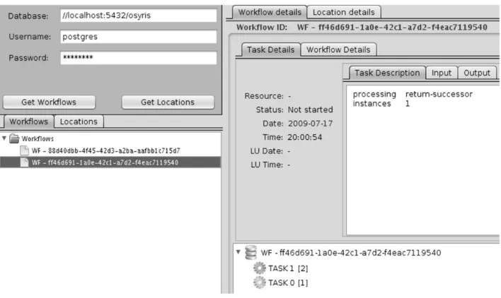
4.7. The Workflow Manager. Workflow tasks are executed by WS located in various geographical places. This can lead to problems such as: response delays due to either time required to transmit large amount of data or network overuse; task failures due to resource unavailability because of service failures etc. Even though these problems can be overcome by taking adaptive measures such as dynamic task rebalancing, task cloning or other methods, it is important to overview and keep track of all these problems for later statistics, rescheduling and other administration policies. OSyRIS provides an administrative interface (see Figure 4.1 and Figure 4.7) where can be observed information such as: the status of each workflow task (not running, running, completed, paused or aborted); the service which executes them and if available the location; how long it took to execute them or how often a certain service is used.
5. Case Study: Composing Image Processing Operations. OSyRIS was initially developed for the GiSHEO e-learning environment [22]. The goal of GiSHEO is to offer an easy to use environment where students can apply various processing operations on large satellite images (several hundreds of gigabytes each). As it has been shown [36] image operation composition can be successfully used in natural sciences where it can offer relevant information such as the position of ancient human settlements, flood coverage and evolution, vegetation areas etc.
The OSyRIS engine has the role of receiving and orchestrating client requests comprising of a workflow made up of several image processing operations. A typical client request consists of a workflow description expressed in SiLK. The engine receives the request, checks the workflow validity, sends back a workflow id token and fires the rules. Each workflow task receives and produces one or more satellite images depending on the underlying processing operation. Once the workflow finishes the result is sent back to the client together with the id token. Due to the large size of the images the workflow will not handle the actual images but will instead reference them using unique identifiers. Based on each reference the image processing WS will take the image from a repository, process it and return a new reference to the resulted image.
Fig. 4.6.User interface for the Visual Workflow Designer
Fig. 4.7.User interface for the Visual Workflow Manager
So GiSHEO also requires additional meta-attributes includingdataset,datagroup,processingand argument-list.Dataset is an identifier that represents the dataset containing the image;Datagroup is an identifier for the datagroup where the imagedataset is stored in; isLast is used to mark that the task is the final task of the workflow; processing represents the image processing operation assigned to the task and is described using C function prototype syntax; andargument-list contains the list of predefined processing arguments.
The following SiLK code presents an example consisting of a workflow which computes the Normalized Difference Vegetation Index (NDVI) [30]. The NDVI is computed by applying the following formula: N DV I= (N IR−RED)/(N IR+RED), where NIR and RED stand for the near-infrared and respectively the red bands of the multi-spectral satellite image. The workflow first extracts the red and near-infrared bands and then uses the output images to compute the NDVI:
# Initial activation task
A0:=[o1:output="datasetID","instances"="1"];
# The following tasks belong to the processing workflow A:=[i2:input, o1:output, "processing"=
‘‘image extract-band(band#image)","argument-list"="<band=red>"]; B:=[i2:input, o1:output,"processing"=
‘‘image extract-band(band#image)","argument-list"="<band=infrared>"]; C:=[i1:input, i2:input, o1:output, ‘‘datagroup"="datagroupID",
‘‘dataset"="datasetID","processing"="image compute-ndvi(image#image)", ‘‘isLast"="true"];
# Extract red and infrared bands from the initial image A0[a=o1] -> A[i2=a], B[i2=a];
# Compute NDVI using red and infrared bands A[a=o1], B[b=o1] -> C[i1=a#i2=b];
6. Conclusions and Future Work. OSyRIS aims to provide a flexible and self adaptive environment in which tasks are linked naturally by ECA rules following a nature inspired paradigm. The platform consists of several components: workflow engine, the SiLK language interpretor, the scheduling module, the automatic workflow generator and the visual workflow designer and administrator. SiLK, a simple workflow language, al-lows to easily define task semantics or ontologies by using task attributes, meta-attributes, and task relationships through the use of inference rules. It is based on the concepts described in [32, 33].
OSyRIS has several particularities that distinguish it from other existing solutions. First, it uses a simple rule mechanism, inspired from chemical reactions, from which users can develop their own custom constructs. Second, it has a self adaptive resource selection and a scheduling mechanism mixed with the support for task semantics and ontology definition. Third, self-adaptiveness is applied also in terms of failure handling and task scheduling.
OSyRIS has been tested on the GiSHEO e-learning environment where it has been successfully used to compose image processing requests with applications in the fields of archaeology and geography. Further com-parisons with other approaches are planned in the near future. Additional technical details on the OSyRIS platform can be found at the GiSHEO website [22].
REFERENCES
[1] Activebpel homepage, 2009. http://www.activebpel.org/(accessed November 18th, 2009).
[2] Java message service 1.1, 2009. http://java.sun.com/products/jms/(accessed November 19, 2009).
[3] M. J. Adams,Facilitating Dynamic Flexibility and Exception Handling for Workflows, PhD thesis, Queensland University of Technology, 2007.
[4] A. Ankolekar, M. Burstein, J. Hobbs, and et al.,DAML-S: Semantic Markup for Web Services, 2001. http://www-2. cs.cmu.edu/~softagents/papers/SWWS.pdf (accessed March 30, 2009).
[5] M. Arbib,The Handbook of Brain Theory and Neural Networks 2nd Ed., MIT Press, 1995. [6] M. Bali,Drools JBoss Rules 5.0 Developer’s Guide, Packt Publishing, 2009.
[7] J. Banˆatre, P. Fradet, and Y. Radenac,Programming self-organizing systems with the higher-order chemical language, International Journal of Unconventional Computing, 3 (2007), pp. 161–177.
[8] J.-P. Banˆatre and D. Le M´etayer,Programming by multiset transformation, Commun. ACM, 36 (1993), pp. 98–111. [9] W. Banzhaf, P. Nordin, R. Keller, and F. Francone,Genetic Programming—An Introduction, Morgan Kaufman
[10] T. D. Braun, H. J. Siegel, and N. Beck,A comparison of eleven static heuristics for mapping a class of independent tasks onto heterogeneous distributed computing systems, Journal of Parallel and Distributed Computing, 61 (2001), pp. 801–837. [11] A. Cˆarstea, G. Macariu, and M. Frˆıncu,Description and execution of patterns for symbolic computations, in Procs.
SYNASC09, Timisoara, Romania, September 2009.
[12] H. Casanova, A. Legrand, D. Zagorodnov, and F. Berman,Heuristics for scheduling parameter sweep applications in grid environments, in Procs. 9th Heterogeneous Computing Workshop (HCW), Cancun, Mexico, May 2000, pp. 349–363. [13] A. Charfi and M. Mezini,Ao4bpel: An aspect-oriented extension to bpel, World Wide Web, 10 (2007), pp. 309–344. [14] S. Chun, V. Atluri, and N. Adam,Domain knowledge-based automatic workflow generation, in Proceedings of the 13th
International Conference on Database and Expert Systems Applications (DEXA’02), London, UK, 2002, Springer-Verlag, pp. 81–92.
[15] D. Churches, G. Gombas, A. Harrison, J. Maassen, C. Robinson, M. Shields, I. Taylor, and I. Wang,Programming scientific and distributed workflow with triana services: Research articles, Concurr. Comput. : Pract. Exper., 18 (2006), pp. 1021–1037.
[16] E. Deelman, G. Singh, M. Su, and et al.,Pegasus: A framework for mapping complex scientific workflows onto distributed systems, Scientific Programming, 13 (2005), pp. 219–237.
[17] J. Fern´andez, R. Hoffmann, and A. Valencia,ihop web services., Nucleic acids research, 35 (2007), pp. 21–26.
[18] C. Forgy,Rete: a fast algorithm for the many pattern/many object pattern match problem, Expert systems: a software methodology for modern applications, (1990), pp. 324–341.
[19] M. Frˆıncu, S. Panica, M. Neagul, and D. Petcu,Gisheo: On demand grid service-based platform for earth observation data processing, in Procs. of HiperGRID’09, Politehnica Press, 2009, pp. 415–422.
[20] M. E. Frˆıncu, Distributed scheduling policy in service oriented environments, in Procs. of the 11th Int. Symposium on Symbolic and Numeric Algorithms for Scientific Computing SYNASC’09, IEEE Conference Publishing Series, IEEE Press, 2009.
[21] , Dynamic scheduling algorithm for heterogeneous environments with regular task input from multiple requests, in Procs. of the 4th Int. Conf. in Grid and Pervasive Computing GPC’09, vol. 5529 of Lecture Notes in Computer Science, Springer-Verlag, 2009, pp. 199–210.
[22] GiSHEO,On demand grid services for high education and training in earth observation, 2009. http://gisheo.info.uvt.ro (accessed April 22, 2009).
[23] M. Greenwood, Xscufl language reference, 2004. http://www.mygrid.org.uk/wiki/Mygrid/WorkFlow#XScufl_workflow_ definitions(accessed March 30, 2009).
[24] M. Hiel, H. Weigand, and W. van den Heuvel,An adaptive service-oriented architecture, in Enterprise Interoperability III, ed. K. Mertens, and R. Ruggaber, and K. Popplewell, and X. Xu, Springer, 2008, pp. 197–208.
[25] N. Imyanitov,Is this reaction a substitution, oxidation-reduction, or transfer?, Journal of Chemical Education, 70 (1993), pp. 14–16.
[26] S. Lu, A. Bernstein, and P. Lewis,Automatic workflow verification and generation, Theoretical Computer Science, 353 (2006), pp. 71–92.
[27] G. Macariu, A. Carstea, and M. Frincu,Service-oriented symbolic computing with symgrid, Scalable Computing: Practice and Experience, 9 (2008), pp. 11–25. http://www.scpe.org/vols/vol09/no2/SCPE 9 2 04.pdf (accessed April 16, 2009). [28] M. Maheswaran, S. Ali, H. Siegel, D. Hensgen, and R. Freund,Dynamic mapping of a class of independent tasks onto
heterogeneous computing systems, Journal of Parallel and Distributed Computing, 59 (1999), pp. 107–131.
[29] R. Muller, G. Greiner, and E. Rahm,Agent work: a workflow system supporting rule-based workflow adaptation, Data Knowl. Eng., 51 (2004), pp. 223–256.
[30] R. B. Myneni, F. Hall, P. Sellers, and A. Marshak,The interpretation of spectral vegetation indexes, IEEE Transactions on Geoscience and Remote Sensing, 33 (1995), pp. 481–486.
[31] C. Nagl, F. Rosenberg, and S. Dustdar,Vidre–a distributed service-oriented business rule engine based on ruleml, in Pro-ceedings of the 10th IEEE International Enterprise Distributed Object Computing Conference (EDOC ’06), Washington, DC, USA, 2006, IEEE Computer Society, pp. 35–44.
[32] Z. N´emeth, C. P´erez, and T. Priol,Workflow enactment based on a chemical metaphor, in SEFM ’05: Proceedings of the Third IEEE International Conference on Software Engineering and Formal Methods, Washington, DC, USA, 2005, IEEE Computer Society, pp. 127–136.
[33] Z. N´emeth, C. P´erez, and T. Priol,Distributed workflow coordination: molecules and reactions, Parallel and Distributed Processing Symposium, International, 0 (2006), pp. 260–268.
[34] T. Oinn, M. Greenwood, M. Addis, and et al.,Taverna: lessons in creating a workflow environment for the life sciences: Research articles, Concurrency and Computation: Practice and Experience, 18 (2006), pp. 1067–1100.
[35] G. Paun,Computing with membranes, Journal of Computer and System Sciences, 61 (2009), pp. 108–143.
[36] D. Petcu, D. Zaharie, M. Neagul, S. Panica, M. Frˆıncu, D. Gorgan, T. Stefanut, and V. Bacu,Remote sensed image processing on grids for training in earth observation, in Image Processing, V. Kordic, ed., InTech, Vienna, 2009, in print. [37] J. Schiff,Cellular Automata: A Discrete View of the World, Wiley and Sons, Inc., 2008.
[38] B. Snyder, D. Bosanac, and R. Davies,ActiveMQ in Action (1st ed.), Manning Publications, 2010.
[39] D. Thain, T. Tannenbaum, and M. Livny,Distributed computing in practice: the condor experience., Concurrency - Practice and Experience, 17 (2005), pp. 323–356.
[40] W. M. P. van der Aalst and A. H. M. ter Hofstede,Yawl: yet another workflow language, Information Systems, 30 (2005), pp. 245—275.
[41] H. Weigand, W. van den Heuvel, and M. Hiel,Rule-based service composition and service-oriented business rule man-agement, Proceedings of the International Workshop on Regulations Modelling and Deployment (ReMoD’08), (2008). [42] P. Wolniewicz, N. Meyer, M. Stroinski, M. Stuempert, H. Kornmayer, M. Polak, and H. Gjermundrod,Accessing
[43] WSBPEL,Web services business process execution language version 2.0, 2007. http://docs.oasis-open.org/wsbpel/2.0/ wsbpel-v2.0.pdf (accessed March 30, 2009).
[44] D. Wu, B. Parsia, E. Sirin, J. Hendler, and D. Nau, Automating daml-s web services composition using shop2, in International Semantic Web Conference, 2003, pp. 195–210.
[45] F. Xhafa and A. Abraham,Computational models and heuristic methods for grid scheduling problems, Future Generation Computer Systems, (2009).
[46] C. Zandron, C. Ferretti, and G. Mauri,Using membrane features in p systems, Romanian Journal of Information Science and Technology, 4 (2001), pp. 241—257.
Edited by: Viorel Negru, Adina Magda Florea Received: February 27, 2010