Available Online at www.ijpret.com 656
INTERNATIONAL JOURNAL OF PURE AND
APPLIED RESEARCH IN ENGINEERING AND
TECHNOLOGY
A PATH FOR HORIZING YOUR INNOVATIVE WORK
IMPLEMENTATION OF STORAGE-LESS DVR BASED ON CHARACTERISATION OF
VOLTAGE SWELL AND SAG
PRIYANKA NIKHADE, SANDEEP MAHAJAN
Department of Electrical Engineering, G.H.Raisoni Institute of Engineering & Technology for Women’s, RTMNU Nagpur
Accepted Date: 05/03/2015; Published Date: 01/05/2015
\
Abstract: Voltage swell and sag always remain a serious power quality problem is being most common and gives more economic losses. The DVR is a very perfect solution to address related power quality problem. In conventional system, dc link is used, which makes system bulkier and costlier, also put limit on compensation capability of DVR. Direct ac-ac converter operating without the dc link, which is preferable over conventional technology .As there is no dc link these topology require improved information on instantaneous voltage at point of common coupling and require control scheme depending on these voltage. Therefore a control scheme of DVR with an ac-ac converter, based on characterization of voltage swell and sag .the whole system will simulate in matlab and the results are presented this voltage.
Keywords: Dynamic voltage regulator (DVR), Instananeous symmetrical component theory, Phase jump, Voltage sag
Corresponding Author: MS. PRIYANKA NIKHADE
Access Online On:
www.ijpret.com
How to Cite This Article:
Available Online at www.ijpret.com 657
INTRODUCTION
The most common power quality problems are voltage disturbances in industrial distribution
systems. The voltage sags and swells are the main voltage disturbances that can be due to (i) disturbances in the transmission system, (ii) adjacent feeder faults and (iii) fuse or breaker operation. The voltage-sensitive loads in factories, buildings, and hospitals are damaged due to these disturbances, it results substantial economic data losses. Voltage swell is defined as a short duration increase in rms supply with an increase in voltage ranging from 1.1p.u. to 1.8 p.u. of nominal supply. The main reasons for voltage swells are switching large capacitors or the removal of large loads Voltage is momentary decrease in rms ac voltage at the power frequency of duration from 0.5 cycles to few seconds. Voltage swell and sag are caused by short circuit fault, such as line to ground fault and startup of large induction motor.
A series connected custom power device to mitigate voltage sag as well as swell, dynamic voltage restorer is used. Inject the voltage of required magnitude, phase angle and frequency in series with the distribution feeder to maintain the desired amplitude and waveform even when voltage is distorted or unbalance, is the basic function of dynamic voltage restorer. Basically DVR is the power electronics device. Only 10% voltage sag remain in circuit for 5-10 cycles gives damage in critical load. Due to symmetrical and unsymmetrical fault, voltage sag arises in system. Harmonics in supply voltage can be caused due to uncompensated non linear load. For mitigation of problem caused due to caused due to poor quality of power supply, DVR is used their primary application is to compensate for voltage sags and swells.
A very simple and practical method for voltage swell and sag detection is by calculating RMS voltage for one or half cycle.
Available Online at www.ijpret.com 658
Fig 2 AC-AC interface
ii. Voltage Sag Characteristics
Voltage sag is defined as a decrease in rms voltage at the power frequency for durations of 0.5 cycles to 1 minute which gives the parameters of voltage sag like rms voltage and duration. This also give a numerical value to a sag, the recommended usage is a sag 70%, which means that the voltage is reduced down to 70% of the total voltage, thus a remaining voltage is 30%.Sag magnitude is defined as the remaining voltage during the fault. The power systems faults cause a drop in voltage magnitude also cause change in the phase-angle of the system voltage. The parameters used to characterize voltage sag are magnitude, duration, point-on-wave sag initiation and phase angle jump.
A. Voltage Sag Magnitude
Determine the magnitude of voltage sag in number of ways. The most common method for obtain the sag magnitude is by using rms voltage. Some other alternatives are also there, e.g. fundamental rms voltage and peak voltage. Hence the magnitude of the sag is considered as the residual voltage or remaining voltage during the event. In the case of a three phase system, voltage sag can also be characterized by the minimum RMS-voltage during the sag.
B .Types of voltage sag-
Available Online at www.ijpret.com 659
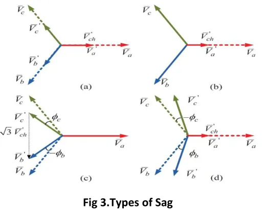
Fig 3.Types of Sag
If the voltage deep is equal in all the three phases then it is called symmetrical sag and it comes under type A sag, If the deep is unequal ,it is called unsymmetric and it comes under type B sag lowest remaining voltage is used to characterize the sag. The phase to phase sag at star connected load called type C sag and sag at the terminals of a delta connected load. It is again divided into various sub -types.
C. Point on Wave
For obtaining exact value of swell and sag duration, start and end of the sag with a great precision is needed. For that one needs to find the so-called “point-on-wave of sag initiation” and the “point-on-wave of voltage recovery”. The point-on-wave initiation is the phase angle of the fundamental wave at which the voltage sag starts.
D. Phase Angle Jump
Available Online at www.ijpret.com 660 E. Voltage Sag Duration
The duration of voltage sag is mainly determined by the fault–clearing time. The duration of a voltage sag is the amount of time during which the voltage magnitude is below threshold is typically chosen as 90% of the nominal voltage magnitude.
ii. Characterization Algorithm
The algorithm combines instantaneous symmetrical component theory and Fourier transform to extract fundamental symmetrical components. Instantaneous symmetrical components that reflect the instantaneous changes in voltages are used to detect disturbances in a system .The sequence components are calculated as follows:
Va0=1/3(va+vb+vc)
Va1=1/3(va+avb+a2vc)
Va2=1/3(va+a2vb+avc)
Where ;a∟120 ,va0 ,va1 and va2 are the instantaneous zero-, positive-, and negative-sequence
components, respectively;va1 and va2 are complex and time varying quantities; and va ,vb and
vc are instantaneous three-phase voltages at the PCC. To work in the presence of harmonics
and distortions, Fourier transform is applied on the instantaneous symmetrical components of the voltage at the PCC.
iv. Switching Logic
Available Online at www.ijpret.com 661
v. Simulation Model
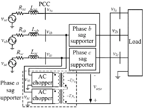
The output of the chopper is injected using an amorphous core-based transformer to minimize losses and to operate in a high switching frequency condition. A chopper across phase belonging to the phase- sag supporter is shown in Fig.
Available Online at www.ijpret.com 662
v. Conclusion
A control scheme based on the characterization of voltage swell is proposed. It is tested on interphase ac–ac converter topology and it is found that the scheme besides compensation gives insight on the limits on compensation imposed by various sag types. Therefore, it aids in the flexible compensation by switching between presag and inphase compensation. The scheme provides 100% compensation for type sag, and for all other types, compensation up to 50% sag magnitude with phase jumps ranging from 60 to 60 for interphase ac–ac topology. The algorithm takes, at most, half a cycle to compensate and it works in the presence of harmonics and unbalance, since the Fourier transform is employed to extract the fundamental component.
Voltage sags have been mainly characterized by magnitude and duration. This paper presents a broad voltage swell, sag and other power system disturbances in terms of its magnitude, duration and phase-angle jump by using MATLAB/SIMULINk.
ACKNOWLEDGMENT
I would like to express my sincere gratitude to my project guide Prof. S. S. Mahajan. I would also like to give my thanks to my mother and father who always stood firmly behind me in achieving this goal. And lastly, I owe my deepest gratitude to my brother and friends for their help during this project.
REFERENCES
1. R. S. Vedam and M. S. Sarma, Power Quality: VAR Compensation in Power Systems. Boca Raton, FL, USA: CRC, 2009.
Available Online at www.ijpret.com 663 3. R. C. Dugan, M. F. McGranaghan, S. Santoso, and H.W. Beaty, Electrical Power Systems Quality. New York, USA:McGraw-Hill, 2004.
4. J. G. Nielsen and F. Blaabjerg, “A detailed comparison of system topologies for dynamic voltage restorers,” IEEE Trans. Ind. Appl., vol. 41, no. 5, pp. 1272–1280, Sep./Oct. 2005.
5. G. Venkataramanan, B. K. Johnson, and A. Sundaram, “An AC-AC power converter for custom power applications,” IEEE Trans. Power Del., vol. 11, no. 3, pp. 1666–1671, Jul. 1996.
6. S. M. Hietpas and M. Naden, “Automatic voltage regulator using an AC voltage-voltage converter,” IEEE Trans. Ind. Appl., vol. 36, no. 1,pp. 33–38, Jan./Feb. 2000.
7. E. C. Aeloíza, P. N. Enjeti, L. A. Morán, O. C. M. Hernandez, and S. Kim, “Analysis and design of a new voltage sag compensator for critical loads in electrical power distribution systems,” IEEE Trans. Ind. Appl., vol. 39, no. 4, pp. 1143–1150, Jul./Aug. 2003.
8. E. Babaei, M. F. Kangarlu, and M. Sabahi, “Mitigation of voltage disturbances using dynamic voltage restorer based on direct converters,” IEEE Trans. Power Del., vol. 25, no. 4, pp. 2676– 2683, Oct. 2010.
9. B. Wang and G. Venkataramanan, “Dynamic voltage restorer utilizing a matrix converter and flywheel energy storage,” IEEE Trans. Ind. Appl., vol. 45, no. 1, pp. 222–231, Jan./Feb. 2009.
10. P. M. Garcia-Vite, F. M. David, and J.M. Ramirez, “Per-sequence vector-switching matrix converter modules for voltage regulation,” IEEE Trans. Ind. Electron., vol. 60, no. 12, pp. 5411– 5421, Dec. 2013.
11. S. Subramanian and M. K. Mishra, “Interphase AC-AC topology for voltage sag supporter,” IEEE Trans. Power Electron., vol. 25, no. 2, pp. 514–518, Feb. 2010.
12. A. Prasai and D. M. Divan, “Zero-energy sag corrector with reduced device count,” IEEE Trans. Power Electron., vol. 24, no. 6, pp. 1646–1653, Jun. 2009.
13. J. Suma and M. K. Mishra, “Instantaneous symmetrical component theory based algorithm for characterization of three phase distorted and unbalanced voltage sags,” in Proc. IEEE Int. Conf. Ind. Technol., Feb. 2013, pp. 845–850.
Available Online at www.ijpret.com 664 15. M. Bollen, “Algorithms for characterizing measured three-phase unbalanced voltage dips,” IEEE Trans, Power Del., vol. 18, no. 3, pp. 937–944, Jul. 2003.