A RECONFIGURABLE PATTERN MATCHING HARDWARE IMPLEMENTATION USING ON-CHIP RAM-BASED FSM
by
Indrawati Gauba
A thesis
submitted in partial fulfillment of the requirement for the degree of Master of Science in Computer Engineering
Boise State University
© 2010
DEFENSE COMMITTEE AND FINAL READING APPROVALS
of the thesis submitted by
Indrawati Gauba
Thesis Title: A Reconfigurable Pattern Matching Hardware Implementation Using On-Chip RAM-Based FSM
Date of Final Oral Examination: 07 May 2010
The following individuals read and discussed the thesis submitted by student Indrawati Gauba, and they evaluated her presentation and response to questions during the final oral examination. They found that the student passed the final oral examination.
v
vi
ACKNOWLEDGEMENT
I would like to sincerely thank my advisor Dr. Nader Rafla for his valuable guidance and support while completing my graduate education. I am grateful for his confidence in me that I could do a good job with my thesis. It has been a great pleasure, in fact, an honor to work with him.
I would also like to thank Dr. Jennifer A. Smith and Dr. Thad Welch for being on my thesis committee and guiding and encouraging me throughout my research work.
vii
ABSTRACT
The use of synthesizable reconfigurable IP cores has increasingly become a trend in System on Chip (SOC) designs. Such domain-special cores are being used for their flexibility and powerful functionality. The market introduction of multi-featured platform FPGAs equipped with on-chip memory and embedded processor blocks has further extended the possibility of utilizing dynamic reconfiguration to improve overall system adaptability to meet varying product requirements. A dynamically reconfigurable Finite State Machine (FSM) can be implemented using on-chip memory and an embedded processor. Since FSMs are the vital part of sequential hardware designs, the
reconfiguration can be achieved in all designs containing FSMs.
In this thesis, a FSM-based reconfigurable hardware implementation is presented. The embedded soft-core processor is used for orchestrating the run-time reconfiguration. The FSM is implemented using an on-chip memory. The hardware can be reconfigured on-the-fly by only altering the memory content. The use of a processor for
viii
can reconfigure itself based on a new incoming pattern and perform a pattern search on a given text without involving a host processor.
ix
TABLE OF CONTENTS
ACKNOWLEDGEMENT ... vi
ABSTRACT ... vii
TABLE OF CONTENTS ... ix
LIST OF TABLES ... xii
LIST OF FIGURES ... xiii
CHAPTER 1—INTRODUCTION ... 1
1.1 Organization ... 3
CHAPTER 2—RECONFIGURABLE HARDWARE & CURRENT APPROACHES .... 4
2.1 Reconfiguration Techniques ... 4
2.1.1 Dynamic Reconfiguration ... 5
2.1.2 Partial Reconfiguration ... 6
2.1.3 Multi-Context Architecture ... 8
2.1.4 Reconfiguration Using On-Chip Memory ... 10
2.1.5 Reconfiguration Using a Self-Reconfigurable Finite State Machine ... 10
2.2 Summary ... 11
CHAPTER 3—RECONFIGURABLE FINITE STATE MACHINE: PROBLEM STATEMENT AND SOLUTION ... 12
x
3.1.1 Reconfigurable Finite State Machines ... 14
3.1.2 Relevance of Reconfigurable Finite State Machines ... 14
3.2 Related Work ... 15
3.3 Proposed Approach ... 19
3.4 Design Strategy ... 20
3.5 Summary ... 22
CHAPTER 4—KMP STRING MATCHING ALGORITHM ... 23
4.1 Relevance of String Matching Algorithm ... 23
4.2 Brute Force Search for String Matching ... 23
4.3 KMP Algorithm ... 25
4.3.1 Skipping Outer Iterations ... 26
4.3.2 Skipping Inner Iterations ... 27
4.4 Summary ... 31
CHAPTER 5—DESIGN IMPLEMENTATION ... 32
5.1 Design Modeling ... 34
5.2 Design Implementation ... 35
5.2.1 Hardware ... 36
5.2.2 Hardware Logic Implementation of the KMP Algorithm ... 41
5.2.3 Processor ... 43
5.2.4 Processor Interface and Control Signals ... 46
5.2.5 Software Implementation ... 50
xi
5.5 Summary ... 52
CHAPTER 6—EXPERIMENTAL RESULTS AND ANALYSIS ... 53
6.1 Simulation Testing ... 53
6.2 Hardware Testing ... 58
CHAPTER 7—CONCLUSION AND FUTURE WORK ... 65
xii
LIST OF TABLES
Table 4.1: Brute force search iteration result for iterations i=0 to i=7 ... 24
Table 5.1: Translation from π[i] to FSM next state transition and output function ... 39
Table 5.2: Slave registers usage description ... 46
Table 5.3: Control signal definitions ... 47
Table 5.4: Control signal values for FSM state transition memory update ... 48
Table 5.5: Control signal values for FSM output memory update ... 49
Table 5.6: Control signal values for setting FSM output and input signal width ... 50
Table 6.1: Clock cycle required for FSM update ... 62
Table 6.2: Performance of the implementation for various values of m with ... 62
xiii
LIST OF FIGURES
Figure 2.1: FPGA configuration approaches: a) Static configuration, b) Dynamic
reconfiguration [8] ... 6
Figure 2.2: Partial reconfigurable architecture ... 7
Figure 2.3: Single context dynamically reconfigurable architecture [8] ... 9
Figure 2.4: Multi-context dynamically reconfigurable architecture [8] ... 9
Figure 3.1: Mealy FSM ... 13
Figure 3.2: Moore FSM ... 13
Figure 3.3: Transition taken during FSM reconfiguration [5] ... 16
Figure 3.4: Reconfigurable FSM implementation [5] ... 17
Figure 3.5: Custom reconfigurable circuit for FSM implementation [6] ... 18
Figure 4.1: Iteration 2 and 3 ... 26
Figure 4.2: Iteration 2 and 4 ... 27
Figure 4.3: Pseudo code with skipped outer iteration ... 27
Figure 4.4: State transition diagram for pattern “ababca” ... 29
Figure 4.5: Phase 2 pattern “ababca” search execution using π[] array ... 29
Figure 4.6: KMP algorithm phase 1: Prefix function computation [3] ... 30
Figure 4.7: KMP algorithm phase 2: Text search [3] ... 31
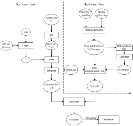
Figure 5.1: Elements and stages of XPS and EDK leading to FPGA configuration ... 33
Figure 5.2: Spartan-3E FPGA Starter Kit Board ... 36
xiv
Figure 5.4: RAM-based FSM implementation ... 38
Figure 5.5: KMP algorithm phase 2: Pattern search ... 41
Figure 5.6: Block diagram of KMP hardware logic ... 42
Figure 5.7: MicroBlaze system with peripheral buses connecting user cores ... 44
Figure 5.8: Hardware architecture of the reconfigurable KMP ... 45
Figure 5.9: Software implementation flow ... 51
Figure 6.1: Simulation waveform of KMP search run for pattern “ababca” ... 55
Figure 6.2: Simulation waveform of KMP search run for pattern “ababca” with text containing two overlapped patterns ... 57
Figure 6.3: Result of pattern search “ababca” at the terminal console ... 60
CHAPTER 1—INTRODUCTION
The rising speed performance of modern FPGAs enabled them to offer possible parallelism of Application Specific Integrated Circuits (ASICs) along with flexibility. However, their increasing manufacturing cost has raised the demand to add more flexibility to System on Chip (SOC) without sacrificing performance. Reconfiguration technologies are viewed by the SOC designers as a tool to achieve this target.
Dynamically reconfigurable hardware has added a new dimension to SOC design by combining the capability introducing modifications to post-fabrication functionality modification (not present in conventional ASICs) with the spatial/parallel computation style (not present in instruction set processors). These technologies allow the hardware to be customized after device fabrication to meet the instantaneous needs of a specific application.
FPGA devices contain configurable logic blocks whose functionality is
determined through the programmable configuration bits. Vendor specific tools generate a configuration bit-stream to program FPGA devices. Reconfiguration technologies manipulate the configuration bit-stream to achieve reconfiguration. Partial
reconfiguration of FPGAs is based upon the partial manipulation of configuration bit-streams and downloading them to FPGA devices. Self-reconfiguration can also be realized by multi-context FPGA devices [2, 3]. These FPGA devices support dynamic reconfiguration by allowing the storage of multiple configuration bit-streams in FPGA memory and switching between them using a dedicated signal for control. A multi-context FPGA-based self-reconfigurable string matching hardware design was first presented in 1999 [3].
The advent of Static Random Access Memory (SRAM) based FPGAs has made Run Time Reconfiguration (RTR) feasible by changing the value of the configuration stream stored in SRAM cells to realize a new function. A RTR system is a heterogeneous system consisting of at least one FPGA and a configuration manager. Markus Koster and Jurgen Teich [5] proposed a hardware configuration manager design for the
implementation of a RTR Finite State Machine (FSM) in 2002 [5]. The external (host) or embedded processor can also be used to achieve RTR. The use of an embedded processor in such a capacity is proposed by Joao Canas Ferreira in 2005 [17].
logic cells than traditional flip-flop based implementations. This can be utilized to implement the sequential part of the design as an FSM. The functionality of such sequential design can be reconfigured by altering the functionality of the finite state machines. Reconfigurable FSMs have given an alternative to achieving reconfiguration without the need to manipulate configuration bit-stream.
This thesis provides an in-depth discussion of a memory-based FSM
implementation that is dynamically reconfigurable using an embedded processor. A hardware-software co-design is developed as a run-time reconfigurable system. The Knuth-Morris-Pratt string matching hardware is implemented to prove the feasibility of this approach [13]. This thesis provides a core framework design for a portable hardware design for run-time reconfiguration for FSM-based sequential designs.
1.1 Organization
The organization of this thesis is as follows. Chapter 1 briefly introduces and outlines the thesis organization; Chapter 2 reviews the current reconfiguration techniques. Finite state machines and implementation approaches of reconfigurable FSM are detailed in Chapter 3. Since KMP string matching algorithm is implemented to prove feasibility of concept, Chapter 4 provides the explanation of the KMP string matching algorithm in detail.
CHAPTER 2—RECONFIGURABLE HARDWARE & CURRENT APPROACHES A system which allows changing behavior or adds new features to an existing system after product manufacturing is defined as an upgradable system. Device
manufacturers search for a field upgradeable system to meet the stringent time-to-market requirement. Such a system enables manufacturers to release the initial version of the product to the market, and extends the features during the product life time by system upgrades. The FPGA-based reconfigurable hardware provides a similar solution by adding reconfiguration capability to the system to meet additional product requirements.
In a static implementation strategy of FPGA-based systems, the implementation uses a fixed configuration of hardware logic resources. These resources are configured before the system operates, and maintains the same configuration throughout the operation. The techniques of reconfiguration allow the hardware logic resources to accommodate different applications or to add new features to the existing application. Much work has been accomplished on device reconfiguration techniques for FPGA-based systems. This chapter reviews some of the most common reconfiguration techniques.
2.1 Reconfiguration Techniques
specific logic resources such as LUTs (Loop up table array) and flip-flops. After
synthesis, a Place and Route tool performs the task of placing and routing the synthesized logic onto the target device and generates the bit-stream file. The generated bit-stream (configuration bit-stream) file is downloaded onto the FPGA to implement the design on its fabric.
2.1.1 Dynamic Reconfiguration
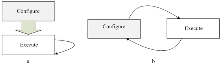
Traditional FPGA-based systems are usually configured before starting the execution of the application and referred to as statically reconfigurable. To reconfigure the FPGA, the system has to be halted till reconfiguration is done and then the FPGA needs to be restarted with the new configuration. On the other hand, a dynamically reconfigurable system allows one to run the reconfiguration and application execution in parallel. It is based on the concept of virtual memory. When the physical resources of the FPGA is much less than the overall system requirement, the system is divided into
hardware segments that do not need to run concurrently and a dynamic allocation scheme is used to re-allocate the logic resources to hardware segments at run time [8]. It enhances the system flexibility and performance by dynamically loading and unloading the
optimized circuit configuration during system operation. Dynamic reconfiguration is supported on FPGA devices via JTAG or vendor specific external interface ports. External intelligent hardware such as a processor or microcontroller or dedicated hardware blocks residing on the FPGA itself are used to reconfigure the device.
reconfiguration approaches. A statically configured FPGA system, once configured cannot be reconfigured again, while a dynamically configurable FPGA system can be reconfigured multiple times to implement different functionalities.
Figure 2.1: FPGA configuration approaches: a) Static configuration, b) Dynamic
reconfiguration [8]
2.1.2 Partial Reconfiguration
Some applications require modifying only part of the circuit for reconfiguration. In such cases, partial reconfiguration can be used. Partial reconfiguration is an important feature in some FPGA architectures. It is the ability to reconfigure a portion of a FPGA while the remainder of the design is still operational. Certain areas of a device can be reconfigured while other areas remain operational and unaffected by reprogramming [8, 12]. Partial reconfiguration is done while the device is active without the need of
restarting.
On Xilinx FPGA devices, Virtex series (such as Virtex II and Virtex Pro) support dynamic partial reconfiguration via an Internal Configuration Access Port (ICAP)
becomes available after an initial (externally controlled) configuration is complete and allows the designer to control device reconfiguration at run-time. The reconfiguration is controlled by an on-chip embedded processor via ICAP. The advantage of
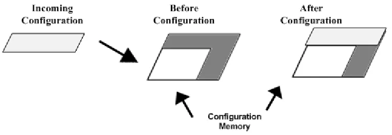
reconfiguration via ICAP is that it does not require an external configuration port. It can partially alter the configuration bit-stream. The drawback of this technique is that it is slow and it must perform a memory read operation first. Figure 2.2 shows a partial reconfigurable architecture inside FPGA memory. The first left block represents the partial configuration that needs to be loaded on the FPGA. The next block represents the configuration memory before reconfiguration takes place. The dark grey area in this block is the unused area of the configuration memory while the area in white is the configured part. The final block shows the status of configuration memory after reconfiguration.
Figure 2.2: Partial reconfigurable architecture
communications and allow signals to cross over the module boundaries. At each reconfiguration, the bus macro is used to establish the unchanging routing channels between the modules to guarantee correct connections.
Difference-based partial reconfiguration is accomplished when a very small change in the design is needed to achieve the reconfiguration. Instead of storing the full configuration stream, the difference-based configuration bit-stream stores only the difference between the base configuration and the configuration needed to reconfigure the device. At first, a configuration bit-stream is generated. Then, a vendor specific software tool (such as FPGA-Editor) is used to make changes in the existing
configuration to generate the difference-based configuration bit-stream. Since bit-stream differences are extremely small compared to the bit-stream of the entire device, fast switching between configurations of module(s) is possible.
2.1.3 Multi-Context Architecture
Self-reconfiguration can be realized by multi-context FPGA devices that allow on-chip manipulation of configuration bit-streams [3, 8]. Multi-context FPGA devices have on-chip RAM that can store multiple pre-programmed configuration contexts (configuration bit-streams). Only one context can be active at a given time. The
FPGA can be visualized as multiple planes of configuration memory stacked on each other. Each plane can store an individual configuration bit-stream. Since single context FPGAs have only one memory plane, they can store only one configuration, on the other hand multi-context FPGA configuration bit-stream can store several configurations on any of the available memory planes. For example, in Figure 2.4, the incoming
configuration bit-stream is stored on the top memory plane.
Figure 2.3: Single context dynamically reconfigurable architecture [8]
2.1.4 Reconfiguration Using On-Chip Memory
All the reconfiguration techniques described previously are based on manipulation of the configuration bit-stream. The on-chip memory (memory available on the FPGA device itself that can be accessed by the design) provides another alternative way to achieve reconfiguration. Instead of implementing logic that alters the configuration bit-stream, logic to control the functionality on-the-fly via altering on-chip data memory can be implemented. The self-reconfiguration can be abstracted as a set of programmable primitive logic elements (logic-lets) and a network of programmable interconnection networks [4]. These elements are an application-specific hardware block used to implement some logic functionality. For example, given a block to implement an 8-bit arithmetic unit, a 16-bit arithmetic component can be realized by connecting two of these 8-bit arithmetic units. The interconnection networks can be considered as a sort of
multiplexer, which is controlled by memory bits. Two logic elements can be connected by interconnection networks. The functionality of logic-lets and interconnection between them can be altered by the memory-based lookup-up table. A problem-specific control circuit determines the functionality and interconnection between them. In this way, the control circuit performs self-reconfiguration.
2.1.5 Reconfiguration Using a Self-Reconfigurable Finite State Machine
transitions and/or their outputs. A lot of research has been done to develop various techniques of reconfigurable FSM implementation such as F-RAM and G-RAM based FSM, Forward Transmission Expression (FTE) based FSM, RAM/ROM based
hierarchical FSM etc. [4-7]. This is the most flexible way to achieve run-time
reconfiguration which, can be applied to almost any FPGA platform and is explored in this research.
2.2 Summary
Functionality implemented on FPGA logic resources can be altered by downloading a manipulated configuration bit-stream to the device. While partial reconfiguration usually uses an external access port to download the modified
CHAPTER 3—RECONFIGURABLE FINITE STATE MACHINE: PROBLEM STATEMENT AND SOLUTION
This chapter describes in brief finite state machines (FSMs) and their relevance. Then, it reviews existing approaches to reconfigurable FSM implementation. A solution to avoid some of the drawbacks of existing approaches is presented. A brief design strategy of the proposed solution is also discussed.
3.1 Finite State Machines (FSMs)
Finite state machines model the behavior of a system or a complex object, with a limited number of modes or states, where states or modes change with circumstances. A finite state machine consists of four main elements:
1) States that define behavior and may produce actions (outputs). 2) State transitions or changes from one state to another.
3) Conditions to allow changes from one state to another.
reduce the complexity of the mathematical model required to establish many important properties in the theory of computation.
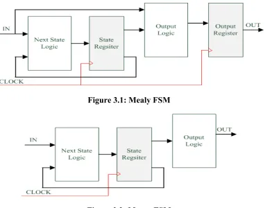
For practical applications, FSMs can be broadly divided in two types: Mealy and Moore FSMs. A Moore FSM is the state machine whose output vectors are a function of the current state only and do not depend on the input vector. On the other hand, with a Mealy FSM, output vector and next state depend on both the current state and input vector. The block diagram of Moore and Mealy FSMs are shown in Figure 3.1 and Figure 3.2, respectively. For this implementation, Moore type DFA FSMs are considered.
Figure 3.1: Mealy FSM
3.1.1 Reconfigurable Finite State Machines
A reconfigurable finite state machine can be defined as a formal finite state machine, which has the ability to change output function and transition function or both during operation [5]. If the reconfiguration is initiated autonomously by the system itself, the FSM is called self-reconfigurable. Reconfiguration can also be initiated by external events, known as reconfiguration events.
3.1.2 Relevance of Reconfigurable Finite State Machines
Digital systems with statically and dynamically modifiable FSM functionality are required in a number of practical applications. They can be used in communication systems, in a crypto-processor, in embedded controllers, etc. Applications that need reconfigurable FSMs can be divided in two categories:
1. Autonomous sequential modules that are components of more complicated digital systems. For example, reconfiguration of a Mealy FSM that detects a sequence of two or more successive zeros makes it possible to change to detect successive ones instead of zeros.
with some pre-defined properties, etc. If a control unit is modeled by a reconfigurable FSM, it is possible to increase its performance by modifying the functionality of its FSM.
The design of MPEG4 natural video decoders and hardware implementation of string matching algorithms are examples of the use of reconfigurable FSM.
3.2 Related Work
A reconfigurable FSM can be realized by using distributed on-chip memory. An approach to implement such an FSM is presented in [5]. In this FSM implementation, two memory blocks, F-RAM and G-RAM, are used to implement the state transition and output functions of the FSM, respectively. The transition sequence required to
reconfigure the initial FSM (referred to as a delta transition) is determined by a heuristic approach. The reconfiguration is realized by taking a sequence of delta transitions where, during each transition, the output and state transition function are updated until the FSM is reconfigured into the target FSM. Figure 3.3 shows the transition of a FSM used to count the number of ones in a bit-stream to a FSM that counts the number of zeros instead. Step one shows the original FSM and Step 4 shows the target FSM. The
Figure 3.3: Transition taken during FSM reconfiguration [5]
Figure 3.4: Reconfigurable FSM implementation [5]
memory. The architecture of such an FSM is shown in Figure 3.5. The input vector is fed to a combinational logic block having the FTE. The comparator compares the current state with the next state. If a mismatch between the current and next state is found, a new FTE from memory is loaded into the combinatorial block.
Figure 3.5: Custom reconfigurable circuit for FSM implementation [6]
Another approach is based on RAM/ROM hierarchical FSM implementation. Reconfiguration is achieved either by swapping pre-allocated areas on a partially dynamically reconfigurable FPGA, or by reloading memory-based cells in statically configured FPGAs [7]. In this approach, the number of reconfigurations is limited and depends on the size of the design and available chip area. To reconfigure the statically configured FPGA, a software model of the reconfigurable FSM has to be constructed and verified on the host system. Then, the bit-streams for memories such as MRAM,
system. After verification, these respective arrays are formally converted into the bit-streams for the FPGA, which can be downloaded using the dual-port capability of FPGAs. Again with this approach, a host system is required for generating configuration bit-streams.
An approach to implement reconfigurable hardware for string matching using the KMP algorithm is described in [3]. Reconfiguration is achieved via switching between multiple configuration contexts of a multi-context FPGAs. The pattern-specific back edges are constructed in the form of FSM, which is mapped onto hardware using a pre-configured template. With this approach, a specific (multi-context) feature is required for reconfiguration and a different context needs to be computed for each pattern. It also requires direct manipulation of configuration bits by the host processor. Another flaw with this technique is that the maximum achievable clock frequency of the system depends on the search pattern and increases with the pattern length.
Another method for KMP implementation using on-chip memory-based logic-lets is explained in [4]. These logic-lets can be connected in a network by altering the
contents of memory-based FSMs. The FSM is computed for each specific application.
3.3 Proposed Approach
Traditional reconfiguration approaches require generation of configuration sequences in the form of technology dependent bit-streams. A reset is needed for a new reconfiguration to take effect. In multi-context FPGA-based reconfiguration methods, these pre-compiled configuration bit-streams need to be stored in configuration memory. Since there is a limited configuration memory space on FPGA devices, the number of reconfigurations is limited to the available configuration memory depending upon the size of configuration bit-streams. The use of an on-chip processor for reconfiguring the FSM eliminates the dependency upon a dedicated design of a hardware re-configurator and a limited number of reconfigurations. The use of the proposed approach also avoids the need of a reset to achieve reconfiguration. It also eliminates the effort exerted on generating configuration bit-streams for each configuration and saving these onto configuration memory. The proposed technique speeds up the hardware pattern search.
With the use of an embedded processor (soft-core such as MicroBlaze or hard-core processor such as Power PC), reconfiguration can be done on-the-fly [8, 23]. The speed of reconfiguration depends only on the processor clock cycles required to update the FSM memory contents. This approach is more generic than traditional reconfiguration approaches as it does not depend on device-specific features.
3.4 Design Strategy
reprogramming the RAM with a new or updated state transition table and output function table. The embedded soft-core processor (MicroBlaze) is used for reconfiguration.
This implementation strategy provides the flexibility of changing the width of input and output vectors using a multiplexer at the input and latches at the output. This strategy can be used in designs that need varying widths of input and output vectors. The multiplexers are enabled/disabled by controlling the bits stored in the memory, and updated by changing the contents of corresponding memory bits. The width of these vectors can be reconfigured by updating the contents of the memory locations providing the necessary control signals.
Several efficient software-based string matching algorithms such as Boyer-Moore Algorithm, Berry-Revindran, Suffix tree, Morris-Pratt, Knuth-Morris-Pratt (KMP) algorithm, and Colussi algorithm exist [15]. The KMP algorithm is one of the most efficient pattern matching algorithms that uses an FSM for search execution. Therefore, it is an ideal candidate for reconfigurable hardware implementation using a memory-based FSM. Also, previous hardware implementation of KMP algorithms is used as a base for performance comparisons with the proposed technique [3, 4].
3.5 Summary
A reconfigurable FSM gives flexibility to change the functionality of sequential digital systems without the need of an external configuration bit-stream manipulation. Various techniques have been devised for efficiently implementing the FSM. On-chip memory-based FSM implementation is the simplest method of implementing a
CHAPTER 4—KMP STRING MATCHING ALGORITHM String matching algorithms are considered ideal models for dynamically
reconfigurable FSM implementations. The string matching problem consists of finding all occurrences of a pattern within a given text. This chapter gives a brief overview of a naive method of brute force string matching. Then, the KMP string matching algorithm is described in detail. Later in Chapter 5, the design and implementation of the proposed system is explained using the same test pattern. In Chapter 6, simulation waveforms of the search execution of the same test pattern are presented.
4.1 Relevance of String Matching Algorithm
The string matching problem has very high relevance to the field of Computer Science. Problems such as intrusion detection engines for internet network security, text processing, and pattern recognition and image matching present some examples where the string matching algorithm can be applied. Biology is another field that benefits greatly from such string matching problems. Finding patterns of DNA inside longer sequences has become central in the analysis of human genomes.
4.2 Brute Force Search for String Matching
of n character length, the search procedure is as follows: Starting at any position i, the do-loop compares the characters of the pattern with the text characters until a mismatch is found. If a mismatch is found at some position, for example i + j, it starts searching again at position i +1. This would lead to a very simple but inefficient search. Suppose a search pattern consisting of character array ‘ababca’ has to be searched within the text
consisting of character array ‘tabacababcaxtab’, several iterations of the brute force search using loops have to be executed. Table 4.1 tabulates the iterations verses matched characters for this iterative process. Column 1 in the table lists the iteration number and row 2 lists the characters of the text string. ‘X’ is placed where a mismatch between text characters and pattern characters is found.
Table 4.1: Brute force search iteration result for iterations i=0 to i=7
Character Number Pattern
Iterations
1 2 3 4 5 6 7 8 9 10 11 12
t e a b a c a b a b c a
i=0 X
i=1 X
i=2 a b a X
i=3 X
i=4 a X i=5 X i=6 A b a b c a
The table shows that the attempt to search the pattern at column position 4 in iteration 3, after a mismatch in iteration 2 at column 6, does not yield any match.
such that its first j – 1 characters are exactly equal to h - 1 (where h < m, m is pattern length) characters starting at the second position in the search pattern itself. For example, in search pattern “aaabca”, the first and second characters (‘aa’) are exactly similar to the second and third character (‘aa’) within the same pattern ‘aaabc’. This pattern has to be searched from a text that contains character string “aaaabca”. It can be noticed that the search pattern contains three consecutive characters of ‘a’ while the text contains 4 consecutive characters of ‘a’. If the pattern search starts at character position ‘0’, then the first iteration i = 0 will find a mismatch at the 3rd character position. Next iteration i + 1(search start at second character ‘a’) will find the pattern match. If the pattern is not such that first j – 1 characters are exactly equal to h – 1 characters starting at the second position, then trying to match the characters from position i + 1 in the text with the pattern would be wasteful and should be avoided. The time complexity of this algorithm is O (mn). In the worst case (if text does not contain any search pattern), m x n
comparisons need to be performed to know that there is no match pattern, where m is the length of search pattern and n is the length of the text.
4.3 KMP Algorithm
The KMP algorithm is one of the most efficient pattern matching algorithms for exact string searches. It was conceptualized by Donald Knuth and Vaughan Pratt, and independently by J. H. Morris. They published a paper “Fast pattern matching in strings” jointly in 1977 [13]. The main features of the KMP algorithm are:
Performs the comparisons from left to right.
Searching phase in O(n+m) time complexity (independent from the alphabet size); Delay is bounded by log (m), where is the golden ratio and given by
The KMP string algorithm bypasses the re-examination of previously matched characters by employing the fact that when mismatch occurs, the pattern characters themselves embed sufficient information to determine where the next match would occur. The KMP algorithm reduces the search work of the naive method in two ways: skipping outer iteration and skipping inner iterations. To explain both, the pattern search example described in Section 4.1 is extended further as described next.
4.3.1 Skipping Outer Iterations
Some iterations can be skipped for which no match is possible. For example, if a partial match is found in an iteration, it should be overlapped with the new match to be found. As shown in Table 4.1, iteration 2 has a mismatch at the fourth position (column 6). If the search starts again from column 4 in iteration 3, a conflict in the placement of the characters is found and a mismatch occurs. Iterations 2 and 3 are shown in Figure 4.1.
i=2: a b a i=3: a b
Figure 4.1: Iteration 2 and 3
i=2: a b a i=4: a Figure 4.2: Iteration 2 and 4
The overlap of two strings x and y is the longest word that is a suffix of x and prefix of y. The number of iterations that can be skipped is the largest overlap in the current partial match. Figure 4.3 shows the pseudo code for string matching with skipped iterations [16]. Two loops ‘while’ and ‘for’ are used for pattern search. The outer while loop is for iteration and the inner for loop for pattern character comparison with the text at any iteration i. If a mismatch at any position j is found, the iterations for the overlapped charactersare skipped.
i=0;
while (i<n) {
for (j=0; T[i+j] != '\0' && P[j] != '\0' && T[i+j]==P[j]; j++); if (P[j] == '\0') found a match;
i = i + max(1, j-overlap(T[0..j-1],P[0..m])); }
Figure 4.3: Pseudo code with skipped outer iteration
4.3.2 Skipping Inner Iterations
occurs at the 4th position. We can skip character comparisons in the outer loop by starting the search at the 2nd position in the text string. We can realize that characters “ab” at the 2nd and 3rd position in the text are equal to the characters at the 0th and 1st position in the search pattern and these characters have already been matched in the previous iteration. So we can skip comparing these two characters in the inner loop and restart searching by comparing characters from the 4th position onwards in the text string with the characters from the 2nd position onwards in the search pattern.
The KMP algorithm utilizes these two key ideas to increase the efficiency of the string search [16]. It computes, for each position j in the pattern, the longest prefix that is also a suffix of the first h characters of the same pattern. This information is stored in an integer array often referred to as function π. This function is independent of the text (the string of characters from which the pattern is searched) and can be computed using the pattern only.
The information stored in the π function can be represented by a state machine. Figure 4.4 shows the state transition diagram for pattern “ababca”. Each node in the state diagram represents a character in the pattern and transition arrows are labeled with match and mismatch: a transition arrow connected from any node j to node j+1 for match or a backward arrow to the overlap node for mismatch. For this pattern the calculated array would be
Figure 4.4: State transition diagram for pattern “ababca”
A string search with the KMP algorithm is done in two phases. In the first phase, the π function is computed based on the search pattern. In the second phase, the π
function, computed in the first phase, is used to speed up the pattern search. For each search pattern, the π array is computed and utilized during the pattern search. At each step of the pattern search, a matcher moves from index q in the pattern to index q+1 if a match is found or else moves backward to the node π[q] as connected by the transition arrow from node q. The search execution for pattern “ababca” is shown in Figure 4.5. The first mismatch in iteration i = 0 is found at column j = 4 position. Since π[4] = 2, the search in iteration 2 continues by comparing the pattern at character position 2 with text character at column j = 4 and results in a pattern match.
The algorithms for both phases are listed in Figure 4.6 and Figure 4.7,
respectively. The pattern to be searched is stored in array P[i] and the text string on which the search is to be performed is stored in array T[]. The function “ComputePrefix”
computes the π function and stores it in array π[]. The array π[] is used in the procedure “TextSearch” to search the given text array T[] for the pattern. It can be proved that the KMP algorithm is very efficient and requires only m+n iterations to perform the search [13, 16].
Function ComputePrefix(P) m = length(P);
π[1] = 0; i = 1, q = 0; while( i < m) do
if (P[i] ≠ P[q]) and (q == 0) then ++i;
π[i] = 0;
else if (P[i] ≠ P[q]) and (q ≠ 0) then q = π[q];
else if(P[i] == P[q])
++i; ++q;
π[i] = q;
end if;
end while;
Procedure TextSearch(P,T)
n = length(T); // length of whole text m = length(P);
π = ComputePrefixFunction(P); i = 0, q = 0;
while( i < n) do
if (T[i] ≠ P[q]) and (q == 0) then i++;
else if (T[i] ≠ P[q]) and (q ≠ 0) then q = π[q];
else if (T[i] ==P[q]) and (q ≠ m - 1) then
i++; q++;
else if (T[i] ==P[q]) and (q == m - 1) then
print “match found”
i++; q++;
end if end while
Figure 4.7: KMP algorithm phase 2: Text search [3]
4.4 Summary
String matching algorithms are used to search all occurrences of a pattern within a string of text characters. The KMP string matching algorithm employs the observation that, at a mismatch, the pattern contains enough information to determine the location of the next possible match. It speeds up the string search by skipping the re-examination of previously matched characters. Before search execution, it builds the prefix function table based upon the specific pattern. This table, which can also be viewed as a state machine, is utilized to speed up the search execution. In the proposed implementation, the π
CHAPTER 5—DESIGN IMPLEMENTATION
This chapter describes the tools and techniques used in this research. The system involves hardware/software co-design. The design of both the hardware and software components is discussed in detail.
Xilinx™ provided the EDK 10.1 tool chain for design development [18]. Platform Studio (XPS), a part of Xilinx’s tool set, is used for on-chip processor-based hardware logic description and XPS SDK development environment is used for software
development. The hardware logic design is modeled in VHDL. FSM construction and reconfiguration is designed in software and coded in the ‘C’ programming language. The development stages of hardware and software components and their integration to
Figure 5.1: Elements and stages of XPS and EDK leading to FPGA configuration
The design and implementation of the KMP system is divided into two
components: hardware and software. The hardware component involves processor-based system description and hardware implementation of the KMP algorithm as a user
5.1 Design Modeling
The Xilinx EDK tool provides a user-interactive GUI to describe the on-chip processor-based design [19], while the XPS GUI provides options to customize the processor features and peripherals. MicroBlaze® is customized to include a universal asynchronous receiver/transmitter (UART) and LED peripherals. The UART is used to serially communicate with the host processor for test purposes, while the LEDs are used as a debugging tool for self-testing of the board. The Processor Local Bus (PLB) is chosen to integrate the KMP hardware logic with the processor system.
The FSM design for implementing a KMP finite state machine and KMP search execution logic is modeled as two separate VHDL entities. Xilinx ISE 10.1 is used for creating and synthesizing these models.
The Base System Builder (BSB), part of the XPS tool, is used to create the processor-based project [18]. It generates a MHS file (system.mhs) describing the Microprocessor Hardware Specification and a PBD file (system.pbd) representing the schematic view along with several other supporting files. A MSS file (system.mss) specifying Microprocessor Software Specification is also generated. The Import
Peripheral Wizard is used to integrate the KMP hardware logic design into the processor system. The wizard creates the necessary directory structure and files needed for
logic and FSM creation logic. The driver file for UART communication is modified to add software logic to receive search patterns from a host system and dump debug messages on a HyperTerminal. MicroBlaze system is described as a top module. The KMP design peripheral is imported to the design through the XPS flow. The Xilinx generated software application is modified to access the KMP hardware logic. The developed embedded system is implemented on the FPGA by generating and
downloading the bit-stream into the hardware board. Verification is done to prove the functionality through simulation and testing.
5.2 Design Implementation
Figure 5.2: Spartan-3E FPGA Starter Kit Board
5.2.1 Hardware
A block diagram of the designed system is shown in Figure 5.3. The FSM and KMP logic block constitute the hardware implementation of the KMP algorithm. The KMP hardware is connected to a Processor Local Bus (PLB) via an Intellectual Property Interface (IPIF). The PLB-IPIF provides a bidirectional interface between a user-defined core and the PLB bus. The PLB bus connects peripheral devices to an on-chip processor. The RS232 is used to interface a host PC with the designed system. A customized
Figure 5.3: KMP system block diagram
The hardware implementation of the design is done in two sub phases. First, the RAM-based FSM is realized and tested using a simulation test-bench. Then, the
developed FSM is used for implementing the KMP algorithm. In the second phase, the KMP hardware developed in the first phase is integrated with the MicroBlaze system.
The FSM for implementing a KMP finite state machine and KMP search execution logic is modeled as separate VHDL entities. Xilinx ISE 10.1 is used for creation and synthesis of source files.
FSMs are traditionally implemented in FPGA using state register and some combinational logic. The combinational logic receives the input vector and produces the output vector and the next state vectors. The next state vector is stored in the state
As mentioned earlier, a FSM can be implemented using memory blocks. In the memory-based FSM, state vector (S0, S1, S2… Sn) and input vector (i0, i1, i2, …in) constitute a RAM address vector [5, 24]. The next state is determined by the feedback information: the present state and input vector. For this implementation, embedded block RAM is used for FSM implementation. Two sets of memory blocks, one for storing encoded state transitions (next state function table) and the other for storing the output vector are used. The block diagram for such FSM implementation is shown in Figure 5.4. Memory blocks have dual ports, where one port is synchronous read-write and the other one is synchronous read. The synchronous read-write port is used by the embedded processor to configure the new FSM state transition and output tables into a FSM memory block. A new FSM is constructed to recognize a new pattern. Also, state
transition of the old FSM needs to be reconfigured. The other port of each memory block is accessed by the KMP hardware logic to run the KMP algorithm in the search execution phase.
The FSM is modeled based on the back edges construction (π function). The FSM memory for output function is programmed in such a way that, at any stage of string comparison, the output vector represents the next pattern character. The state vectors are binary encoded to reduce the memory requirement.
As described earlier, the computed prefix function is used to compute the state transition and output functions of the FSM. Consider the pattern “ababca” as an example of which same state transition diagram of Figure 4.4 can be adapted. The calculated prefix function would be π[] = {0, 0, 0, 1, 2, 0}.The length of the prefix function is equal to the pattern length. Table 5.1 shows the translation of the prefix function to the FSM state transition and output functions.
Table 5.1: Translation from π[i] to FSM next state transition and output function
Pattern characters
π[i] Current State
Next state transition (match = 1)
Next state transition (match=0)
Output function
a 0 0 1 0 a
b 0 1 2 0 b
a 0 2 3 0 a
b 1 3 4 1 b
c 2 4 5 2 c
a 0 5 1 0 a
input text character and the pattern character, and column 6 lists the output if a mismatch is found. The FSM will traverse through states 0 to state 5 if a match pattern is found and the corresponding output would be the ASCII code of pattern characters. If the FSM reaches state 5 and a match is found, it transits to state 1 and the most significant bit of FSM output signal is set to ‘1’ for one clock cycle to indicate a match is found and the rest of the bits (bits 6 to 0) outputs 0x62, the ASCII code of the second matched
character. The signal ‘match_addr’ contains a match address that points to the starting location of matched pattern within the text.
The match memory location is calculated by simply subtracting the state value at the current state where match is found from the text memory address counter. The FSM is designed in such a way that at every pattern match, its current state value always is m – 1 (pattern length - 1). The match address is then stored in a specified memory location within the block RAM. To keep a count of the number of occurrences of a match pattern, a hardware counter is implemented. The occurrence counter and memory location of match addresses are accessed by the software via user slave registers.
5.2.2 Hardware Logic Implementation of the KMP Algorithm
The second phase of the KMP search algorithm is realized in the hardware. The algorithm for phase two logic is shown in Figure 4.6 and reproduced again in Figure 5.5. The first three lines of the KMP algorithm calculates the length of the pattern and the prefix function. The length of pattern characters and prefix function is determined in software by the on-chip processor. The ‘while’ loop for pattern search (lines 5-16 in the code snippet) is translated into hardware logic. The algorithm uses two counters: ‘i’ to point current accessed characters position in the text array and ‘q’ to point current
accessed character position in the pattern during search. The counter ‘i’ is implemented in the hardware. The counter ‘q’ is implemented implicitly in the form of an FSM state transition. As the search progresses, the FSM outputs pattern characters stored in the FSM’s output memory block and changes states based on match or mismatch. Procedure TextSearch(P,T)
1 : n = length(T); // length of whole text 2: m = length(P);
3: π = ComputePrefixFunction(P); 4: i = 0, q = 0;
5: while( i < n) do
6: if (T[i] ≠ P[q]) and (q == 0) then
7: i++;
8: else if (T[i] ≠ P[q]) and (q ≠ 0) then
9: q = π[q];
10: else if (T[i] ==P[q]) and (q ≠ m - 1) then
11: i++; q++;
12: else if (T[i] ==P[q]) and (q == m - 1) then
13: print “match found”
14: i++; q++;
15: end if 16: end while
The KMP phase 2 hardware logic is realized using an FSM, one comparator, and a small combinational logic block. The block diagram of the hardware logic is shown in Figure 5.6. The comparison of the text characters with pattern characters is done through an 8-bit hardware comparator. The comparator compares the FSM output vector (FSM outputs pattern characters) with the text memory output (text characters) and generates a match signal. The match signal is fed to the KMP combinational logic, which in turn controls the address counter. The address counter implements the counter ‘i’ of KMP phase 2 logic and is used as an address to access text character from text memory. KMP combinational logic does not increment the address counter if there is a mismatch between a text character and a pattern character, and the FSM is not in state 0, as
mentioned in line 8 ((T[i] ≠ P[q]) and (q ≠ 0)) of the KMP phase 2 algorithm. The match signal concatenated with the next state function forms the address vector and is used to access the FSM’s state transition and output memory. The search result, which includes address locations of the matched pattern and occurrence count of pattern in text, is stored in internal memory blocks.
5.2.3 Processor
As mentioned earlier, the design is implemented on a Spartan 3E FPGA. Since this particular chip does not have a built-in hard-core processor, MicroBlaze soft-core processor is used for receiving a new pattern as an input, back-edge construction, and dynamically reconfiguring the FSM. A MicroBlaze-based embedded system is comprised of a MicroBlaze soft-core processor, on-chip local memory, Standard Bus Interconnects, and on-chip Peripheral Bus (OPB) peripherals.
The MicroBlaze is a 32-bit RISC Harvard-style soft-core processor offered with the Embedded Development Kit (EDK) tool provided by Xilinx to design an FPGA-based system on-chip [19]. It is designed to deliver the highest possible performance on a single FPGA. It is highly customizable according to the application requirement.
Processor instructions and local memory data are transmitted on the Local Memory Bus (LMB), which guarantees a single-cycle access to on-chip block RAM.
The MicroBlaze system architecture is shown in Figure 5.7. FPGA’s on-chip block memory BRAM is connected to a processor via an Instruction Local Memory Bus (ILMB) and a Data Local Memory Bus (DLMB). An ILMB bus is used to access a processor’s instruction cache and a DLMB is used to access a processor’s data cache. There are two standard interfaces available to integrate customized IP cores into a
data access at high speed. They can be used in time critical applications to provide high speed data transfer. Since the designed system does not require point-to-point data access, the Processor Local Bus (PLB 4.6 bus) is chosen to integrate the customized IP core (KMP logic) with the MicroBlaze processor system.
Figure 5.7: MicroBlaze system with peripheral buses connecting user cores
Figure 5.8: Hardware architecture of the reconfigurable KMP
The KMP hardware core is designed to be accessed by user accessible 32-bit wide slave registers. The number of slave registers to be used in the design is chosen during the hardware description of a MicroBlaze system [20]. For this implementation, 9 slave registers are used. Table 5.2 lists the usage of each slave register. The processor boot code, software to implement dynamic reconfiguration, and logic to construct a
Table 5.2: Slave registers usage description
Slave register Description
0 Address for FSM next stage memory 1 Address for FSM output memory 2 Data for FSM next state memory 3 Data for FSM next state memory 4 Data to set FSM output signal width 5 Data to set FSM output signal width 6 Control signal for KMP system 7 Match occurrence count 8 Match address
5.2.4 Processor Interface and Control Signals
Table 5.3: Control signal definitions
Bit Position Signal Name Description
0 Configure 1 - during FSM update 0 - otherwise
1 write_byte_enable 1 - during text memory update 0 - otherwise
2-3 X unused
4 we_ns 1 - during state transition function FSM memory update 0 - otherwise
5 we_ns_a 1 - during state transition memory address update 0 - otherwise
6 we_op 1 - during output function FSM memory update 0 - otherwise
7 we_op_a 1 - during output function memory address update 0 - otherwise
8 en_op_mux 1 - during FSM output vector width setting 0 - otherwise
9 en_in_mux 1 - during FSM input vector width setting 0 - otherwise
10 X unused
11 FSM_reset 1 - to reset FSM logic
The processor initiates the reconfiguration process at each reception of a new pattern as follows. Specific signals are activated by the processor to update FSM memory for the next state and output functions. During an FSM update, the ‘configure’
signal is activated to indicate a reconfiguration is in progress and the KMP core remains in reset state. After FSM update, the ‘configure’ signal is de-asserted, and the KMP
search process runs to find the pattern within the text.
placed on slave register 6 to write-enable the next state memory where memory contents are updated via slave register 2. Table 5.4 lists the corresponding signals and their bit position in slave register 6.
Table 5.4: Control signal values for FSM state transition memory update
Slave Register6
Bit Position Signal Name
Next State Memory Address Update Next State Memory Data Update
0 Configure 1 1
1 write_byte_enable 0 0
2-3 x 0 0 4 we_ns 1 1 5 we_ns_a 1 0 6 we_op 0 0 7 we_op_a 0 0
8 en_op_mux 0 0
9 en_in_mux 0 0
10 x 0 0
11 FSM_reset 0 0
32 bit hex value 0x31 0x11
The process of an output function memory update of the FSM is similar to the next state memory update. The processor first places the starting address of output
Table 5.5: Control signal values for FSM output memory update
Slave Register6
Bit Position Signal Name Output Memory Address Update Output Memory Data Update
0 Configure 1 1
1 write_byte_enable 0 0
2-3 x 0 0 4 we_ns 0 0
5 we_ns_a 0 0
6 we_op 1 1
7 we_op_a 1 0
8 en_op_mux 0 0
9 en_in_mux 0 0
10 x 0 0
11 FSM_reset 0 0
32 bit hex value 0xc1 0x41
Table 5.6: Control signal values for setting FSM output and input signal width
Slave Register6
Bit Position Signal Name Output Signal Width Setting Width Setting Input Signal
0 Configure 1 1
1 write_byte_enable 0 0
2‐3 x 0 0
4 we_ns 0 0
5 we_ns_a 0 0
6 we_op 0 0
7 we_op_a 0 0
8 en_op_mux 1 1
9 en_in_mux 0 0
10 x 0 0
11 FSM_reset 0 0
32 bit hex value 0x101 0x201
5.2.5 Software Implementation
5.4 Design Synthesis and Implementation
The Base System Builder (BSB) is used in XPS to create the MicroBlaze-based project. To boot up the designed embedded processor system, both hardware and software components need to be downloaded to the FPGA and program memory,
respectively. The XPS Software Development Kit combines the XPS generated hardware bit files with the XPS Software executable file into a system.bit file and initializes BRAMs in the bit-stream with the executable code. The generated bit-stream file is downloaded to FPGA using SDK GUI.
5.5 Summary
CHAPTER 6—EXPERIMENTAL RESULTS AND ANALYSIS
This chapter describes the test procedure used to verify the design functionality. A ModelSim PE® 6.4d is used for simulation [22]. A XPS Software Development Kit is used to program the FPGA board with the configuration bit-stream.
System development is done in incremental steps. At each successive step, test cases are developed and simulation is done to verify the correct behavior. At any step, if any violation from the expected behavior is found, the design entry is modified to rectify the violation and the process is repeated until all design expectations are met.
Initially, after completing the design entry, simulation is done using several test-benches. Once the behavior of each block is verified, the design is further synthesized, and placed and routed for SPARTAN 3E FPGA. Design is further verified by
downloading the design on an FPGA board. Xilinx Platform Studio 10.1 is used to generate the configuration bit-stream and the XPS Software Development Kit is used to update the generated bit-stream with the embedded software. The bit-stream is then used to program the FPGA with the developed design. The system under development is debugged via a RS232 HyperTerminal. All the above steps are described in detail in further sections.
6.1 Simulation Testing
for the KMP hardware search is tested by simulation. After verifying the functionality of the hardware blocks, the design is integrated with the MicroBlaze system. XPS generated a VHDL file (user_logic.vhd) that is used for integrating the designed KMP block with the processor.
Simulation is targeted towards testing the implemented FSM and KMP logic for searching a given pattern from the text. A test-bench is designed to provide various test patterns to the implemented logic. The search patterns are also furnished by the
simulation test-bench. Simulation is done for various test patterns of sizes 3 to 20 character lengths. Simulation waveform of a pattern search of one such pattern is shown in Figure 6.1. The search pattern consists of character string “ababca”. The ASCII code corresponding to the characters making the pattern is ‘0x61, 0x62, 0x61, 0x62, 0x63, and 0x61’. The signal ‘configure’ is raised until the FSM is updated, then a search is initiated at its de-assertion. As the text characters match with pattern characters, the FSM traverses through states 0 to 5. When the match pattern is found, a MSB of the FSM output signal is set to ‘1’. As shown in waveform, the FSM output at state ‘5’ is 0xE1 (0x80 | 0x61), Logic operation OR of the logic 1 concatenated with zeros and the ASCII code of the first pattern character. The waveform also shows that the designed logic is capable of searching two consecutive patterns without loss of clock cycles. Signal ‘match_found’ is asserted to indicate a pattern match and signal ‘match_addr’
‘Configure’ Signal de-asserted after updating FSM memory
kmp_reset’ signal de-asserted after one clock cycle and KMP search starts Signal ‘mem_read_m’ asserted to enable text memory read
Address counter ‘mem_addr’ signal which points to text memory start running
Data read from text memory as ‘in_sig_kmp’
FSM remains in state ‘0’ till first match character is received FSM outputs ascii code of first match pattern character ‘comp_out’ =1 if text characters =pattern character
‘comp_out’ is fed to FSM as ‘in_sig_fsm’ FSM traverses through states ‘0’ to ‘5’ text Characters match with the pattern character
FSM outputs MSB=’1’ to indicate pattern match found and ‘match_found’ signal set to ‘1’ for one clock cycle
‘match_addr’ contains the location of first match character at the same time, when match_found’=1
First match at address 0x00000004 is found and ‘comp_out’ sets to ‘1’
FSM again reset to state ‘0’ and output the ascii value of first match pattern
The implemented logic is capable of searching for two consecutive patterns without any loss of clock cycle time. Figure 6.2 shows a simulation waveform of such a search execution. The text string for the test contains “In ababcababce” and the pattern to be searched is “ababca”. The simulation waveform shows that the search execution found two matches at addresses 0x4 and 0x9, which proves that the system can find two
Text memory address counter
Data read from text memory “In ababcababce ” Pattern character output from FSM
Comparator output signal
FSM state transition
Pattern match signal Pattern match addresses
Figure 6.2: Simulation waveform of KMP search run for pattern “ababca” with text containing two overlapped
6.2 Hardware Testing
To test the pattern search functionality, first a text file needs to be stored either in the board’s external memory or in the FPGA’s internal memory. For this
experimentation, a text file is stored in the FPGA’s block RAM. A VHDL source file is coded to instantiate a block ‘RAM’ entity using a ‘RAMB16_S9’ tool construct. Each FPGA device has two types of RAM: Block RAM and Distributed RAM. Block RAM is the dedicated memory inside the FPGA, which can be configured through programming. It does not consume any logic resources of FPGA. Distributed RAM is configured as RAM using FPGA logic resources. The ‘RAMB16_S9’ construct is used to instruct the synthesis tool to use block RAM instead of distributed RAM for implementation. This technique is used to save the FPGA logic resources. This entity instantiates a 2kx8-bit block memory. A software tool written in ‘C’ takes the text file as input and populates the ASCII code of text characters as an initialization code for the ‘RAM’ entity. This VHDL file is compiled and loaded to the FPGA along with the design source file. This procedure is followed to eliminate the need for storing and accessing external memory for testing.
An application, written in ‘C’, is developed to facilitate communication of the designed system on-chip with the host machine. This application used the UART peripheral of MicroBlaze® to establish serial communication with the host machine via HyperTerminal. It receives search commands and search patterns and outputs the search results back on HyperTerminal.
searched within the text is furnished by typing it on the HyperTerminal. The embedded software running on MicroBlaze® receives the pattern characters. It reconfigures the FSM for each instance of received pattern and runs the search. It then accesses the search results via user slave registers and then prints back the search result, count of pattern occurrences, and start locations of each pattern within the text on the HyperTerminal port.
Figure 6.3: Result of pattern search “ababca” at the terminal console
3 to 20 characters. In every case, the number of clock cycles to execute a search is always equal to the number of search iterations. The relationship between the number of
characters and clock cycles after the first match is found is shown in Figure 6.4.
Figure 6.4: Clock cycles vs pattern length after first match
clock cycles required increases by 50 cycles per increase of pattern character. These results are summarized in Table 6.1.
Table 6.1: Clock cycle required for FSM update
S. No. FSM Update function Clock cycles 1 State transition function 300
2 Output function 300
3 Clock cycle increase per character 50
The clock cycle time depends only on the target FPGA device and is independent of the pattern size, as oppose to the implementation described in [3] and reproduced in Table 6.2. The table shows the result of the search execution of pattern length m within the text of n=104 characters long. Column 1 lists length of test patterns, column 2 lists the clock cycle time, column 3 and 4 (TM+TME) lists the time required for mapping of new configurations on the hardware. TE is the search execution time in phase 2.
Table 6.2: Performance of the implementation for various values of m with
n=104 [3]
characters. Column A lists the performance with multi-context FPGA and column B list the results using the proposed approach. The time required for prefix computation and translation depends on the clock speed of the MicroBlaze® core and how and in which language the software is written. Sameer Wadhwa and Andreas Dandalis verified that the maximum achievable clock frequency is 110 MHz for a pattern size of 6 characters on Xilinx Virtex series FPGAs [4]. The maximum achievable frequency with the proposed approach is independent of pattern size and is 97.656 MHz for a SPARTAN 3E 500 FPGA. Higher speeds can be achieved with more advanced FPGAs. It is noticeable that through memory-based FSM reconfiguration, a significant improvement of performance can be obtained.
Table 6.3: Performance comparison for various values of m with n=104
Match Pattern length(m)
Clock Frequency
TCLK(ns)
FSM reconfiguration
time TME(µs)
Phase 2 search execution time
TE(µs)
Total Time
(µs)
A B A B A B A B
4 81.6 20 0.7 11 1428 204 1432 215
8 97.6 20 2.1 18 1830 208 1841 226
16 129.6 20 5.8 34 2511 216 2539 250
![Figure 2.4: Multi-context dynamically reconfigurable architecture [8]](https://thumb-us.123doks.com/thumbv2/123dok_us/8924596.1845030/22.612.152.495.260.384/figure-multi-context-dynamically-reconfigurable-architecture.webp)
![Figure 3.3: Transition taken during FSM reconfiguration [5]](https://thumb-us.123doks.com/thumbv2/123dok_us/8924596.1845030/29.612.157.531.89.272/figure-transition-taken-during-fsm-reconfiguration.webp)
![Figure 3.4: Reconfigurable FSM implementation [5]](https://thumb-us.123doks.com/thumbv2/123dok_us/8924596.1845030/30.612.189.461.95.355/figure-reconfigurable-fsm-implementation.webp)
![Figure 3.5: Custom reconfigurable circuit for FSM implementation [6]](https://thumb-us.123doks.com/thumbv2/123dok_us/8924596.1845030/31.612.142.502.205.442/figure-custom-reconfigurable-circuit-for-fsm-implementation.webp)
![Figure 4.5: Phase 2 pattern “ababca” search execution using π[] array](https://thumb-us.123doks.com/thumbv2/123dok_us/8924596.1845030/42.612.111.540.91.223/figure-phase-pattern-ababca-search-execution-using-array.webp)
![Figure 4.6: KMP algorithm phase 1: Prefix function computation [3]](https://thumb-us.123doks.com/thumbv2/123dok_us/8924596.1845030/43.612.106.321.285.494/figure-kmp-algorithm-phase-prefix-function-computation.webp)