−
An Analytical Model for Long Tube Hydroforming in a
Square Cross-Section Die Considering Anisotropic Effects
of the Material
H. Haghighat
∗, A. Janghorban
Mechanical Engineering Department, Razi University, Kermanshah, Iran.
Article info
Article history:
Received 2016.09.20 Received in revised form 2016.12.24
Accepted 2017.02.12
Keywords:
Tube hydroforming Anisotropic
Square cross-section die
Abstract
In this paper, a mathematical model was developed to analyze the hydro-forming process of a long anisotropic circular tube into a square cross-section die. By using the thickness variation in two extreme cases of friction between the tube and die wall, namely no friction and sticking friction cases, thickness variation in the case of sticking friction was captured in the model. Then by using equilibrium equation for contact length segment, thickness distribution was determined and corresponding forming pressure is predicted. It was shown that in a plane strain state, anisotropic value has no influence on thickness variation of the deformed tube and the forming pressure will increase when the anisotropic value increases. The analytical results of forming pressures and thickness distributions were compared with the results available in the literature to verify the validity of this simple analytical proposed model.
Nomenclature
dL contact length increment P forming pressure
R anisotropic value ro initial tube radius
r radius of arc segment L length of linear segment, contact length
to initial tube thickness ts(x) deformed tube thickness in case of stick-ing at distancexof centerline
tu deformed tube thickness in case of fric-tionless
t(x) deformed tube thickness in guided zoneat distancexof centerline
K strength coefficient n strain hardening exponent
α a parameter where 0≤α≤1 α¯ effective stress
¯
ε effective strain µ friction coefficient
σθ, σz, σt hoop, longitudinal and thickness stress components, respectively
εθ, εz, εt hoop, longitudinal and thickness strain components, respectively
1. Introduction
Tube hydroforming is a process in which a relatively thin-walled circular tube is expanded by an internal pressure and is forced to conform to a shaped die that surrounds it. The tube first elastically and then plas-tically deforms in the die. The deformation proceeds
with an elevation of contact length between the tube and the die as the pressure is increased. Convention-ally, the pressure and the distribution of thickness of this shell along its periphery are unknowns that depend on the geometry, friction coefficient between the tube and the die and material properties. It is desirable, therefore, to develop some simple but efficient
meth-∗Corresponding author: H. Haghighat (Associate Professor) E-mail address: [email protected]
ods to facilitate the pressure and thickness variation prediction in tube hydroforming process [1]
Some of the analytical models and various studies using analytical models and the finite element method have been conducted on plane strain tube hydroform-ing. Chen et al. [1] used finite element simulation to study the effects of forming pressure and coeffi-cient of friction on corner filling in tube hydroform-ing. Kridli et al. [2] used finite element simulation to study the effects of material strain hardening and friction coefficient on the thickness distribution. The two-dimensional hydroforming of circular tubes into rectangular sections was studied by Hwang and Altan [3] using finite element method. Experimental mea-surements of the coefficient of friction during hydro-forming were carried out by Vollertsen and Plancak [4]. Their approach depended on correlating thickness variation along the tube axis with friction coefficient when upsetting an internally pressurized tube. Chen et al. [1] modelled hydroforming of a round tube inside a square die cavity using finite element code, namely ABAQUS/Standard. Kridli et al. [5] reported the results of two-dimensional plane strain finite element models of the tube hydroforming using a square die, which were conducted using the commercial finite ele-ment code ABAQUS/Standard.
The effects of the strain-hardening exponent, initial tube wall thickness, and the die corner radii on corner filling and thickness distribution of the hydroformed tube were discussed. Characteristics of corner filling using a square die have been investigated by Liu et al. [6] via mechanical analyses and numerical simula-tions. Hwang and Chen [7, 8] developed a mathemat-ical model to analyze tube expansion in a rectangular die with sticking friction condition and a square cross-section die with sliding friction condition.
In 2007, Orban and Hu [9] developed an analyt-ical model to determine the variation in the stresses and strains along the tube wall as the forming pres-sure increases to expand the circular tube into a square cross-section die. The friction dependency of the cor-ner filling with frictionless, sliding, and sticking friction conditions was studied. Miller et al. [10, 11] devel-oped a 2D analytical model capable of capturing the effects of tension, pressure, the effects of tension, pres-sure and loading history on the quality of the tubes. The results from this model were in good agreement with experimental results, implying that the 2D an-alytical model can be an efficient tool for paramet-ric study of the forming process at the design stage. Corona [12] extended the model mentioned above to be applicable for arbitrary tube cross-sections. Based on the work of Miller et al. [10] and Corona [12], Guan and Pourboghrat [13] proposed a Fourier-series-based FEA of tube hydroforming for axisymmetric model and Guan and Pourboghrat discussed generalized plane strain model [14]. Smith et al. [15] and Smith and Sun
[16] introduced closed-form formula for planar tube hydroforming analysis. Yang and Ngaile [17] devel-oped an analytical model for planar tube hydroforming based on deformation theory. The developed analyti-cal model was used to predict hydroformed shape, cor-ner fill, wall thinning, and forming pressure. Since the model was based on a mechanistic approach with bend-ing effects included, local strain and stress distribution across the wall thickness could be determined.
In this paper, an analytical model considering inter-facial friction between die and tube was developed to predict the forming pressure, needed to expand a circu-lar long anisotropic tube into a square cross-section die, and the thickness distribution of the product. There was no axial feed and the forming process was under a plane strain state along the axial direction. The pro-posed solution was based on this fact that the thick-ness variation in the case of sliding friction remains between thickness variation of two extreme cases of friction, namely no friction and sticking friction. The analytical results of forming pressure and thickness dis-tributions of the formed tube were compared with the available published results. In spite of the simplicity of the proposed solution, the relative difference between this solution and the solutions based on complicated approaches was comparatively small. This is a great advantage for engineering applications.
2. Analytical Model
2.1. Thickness Variation Assumption
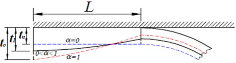
The schematic diagram of a circular long tube that initially just fit inside the square cross-section die is shown in Fig. 1. Taking into account the symmetry of the problem, only one-eighth of the initial tube was considered. In this figure,toandroare the initial thick-ness and outer radius of the tube, respectively. As it is shown in the figure, at any given stroke of the defor-mation, there are two segments in the deformed tube, the guided zone (contact length between deformed tube and the die) and the free expansion segment. When in-ternal pressure is applied, the tube deforms such that the arc length decreases while the contact length be-tween the tube and the rigid die increases. As contact length progresses, the free expansion segment of the tube will stretch and will contact the die wall. It was assumed that the profile of the free expansion segment is a circular arc and the centre of the arc is at the origin O. At any given length of linear segment, con-tact length= L, the arc radius can be determined as
r=ro−L.
thick-ness of the formed tube along the cross-section with the smallest thickness at the corners. Thus the frictional behavior at the material/die interface is crucial in tube hydroforming. To study the friction effects, a simple model and corresponding procedure were proposed. In this work, two extreme cases, with no friction at the die wall or with sticking friction along the entire con-tact length were considered. During the formulation, the following assumptions were employed:
1. the die is rigid.
2. there is no axial feed and it is assumed that plas-tic deformation of the tube is under a plane strain state along the axial direction.
3. the initial cross-section of the tube is perfectly circular and the initial thickness is uniform.
4. the friction coefficient is uniform all over the die surface.
5. during the deformation, the strain is assumed to be constant across the thickness.
6. the effect of lateral pressure on the flow stress is neglected.
7. the material is transversely anisotropic.
Fig. 1. One–eighth of the initial (dashed line) and deformed tube (continuous line).
If contact between the tube and the die is friction-less, the guided zone will have the same strain as that in the arc segment and at any instant the thickness at any point around the tube will be uniform and we have [18]:
tu(L) =
to 4
π− L−ro
ro (
4
π −1
) (1)
For a very high friction coefficient, the guided zone will stick to the die and will not experience further straining. If the tube sticks to the die wall as soon as
it touches it, then the thickness at the first point of contact will be to. In the sticking friction mode, the materials after contact with the die do not move or slide. As the tube becomes progressively attached to the die wall, the thickness will decrease and at point with distance from axis of symmetry, as shown in Fig. 1, it has the value [18]
ts(x) =to (
ro−x
ro )4
π−1
(2)
The deformed tube thickness in guided zone will be non-uniformly varying from the initial thickness at the axis of symmetry of the die to a minimum at the arc segment. For a given radius r, the arc thickness will be less than that for the frictionless case as shown in Fig. 2.
In order to take the friction into account, the pro-posed solution was based on this fact that the thickness variation in the case of sliding friction remains between thickness variation of two extreme cases of friction, i.e. no friction and sticking friction. It was assumed that the thickness distribution in the linear segment and the contact length is approximated as follows:
t(x) =tu(L) +α[ts(x)−tu(L)] (3)
where t(x) is tube thickness at distance of the axis of symmetry, tu(L) and ts(x) can be given by Eqs. (1) and α (2), respectively and is a parameter where 0≤α≤1. The distribution of thickness in the linear segment, contact length, can be determined by finding an appropriate value for using force equilibrium of the linear segment.
Thickness variation along guided zone of deformed tube for frictionless, sticking and friction cases is shown in Fig. 2. When contact between the tube and the die wall is frictionless, α is equal to zero and when full sticking prevails at the interface, αis equal to 1 and for intermediate friction case 0< α <1.
Fig. 2. Thickness variation along contact length for frictionless (α= 0), sticking (α= 1) and intermediate friction cases (0< α <1).
2.2. Stress and Strain Analysis
respec-tively obtained from Hills yield criterion as
¯
ε= √
2(R+ 2)(R+ 1)
3(2R+ 1) ε, (4)
¯
σ= √
3(R2+R+ 1)
(R+ 1)2(R+ 2)σθ (5)
where is the anisotropic value and isσθthe hoop stress. Assuming that the flow stress of the tube material fol-lows the power law of its equivalent strain, the equiv-alent stress is denoted as
¯
σ=Kε¯n (6)
where K and n are strength coefficient and strain-hardening exponent, respectively. At each contact length L, forming pressure P was approximated through consideration of thin-walled cylindrical tube in which the walls offered little resistance to bending and a uniform stress distribution in the wall could be assumed. Then
P =σθ2tt
r (7)
whereris radius of arc,t2 andσθ2 are the tube thick-ness and hoop stress component at the arc segment, respectively.
2.3. Equilibrium of Linear Segment
For a given tube contact lengthL, the shear stress at the die wall was µP. Taking summation of forces act-ing on the guided zone in the direction, as shown in Fig. 3, we obtain
∑
F(x) =σθ2t2−µP L (8)
whereµP Lis the friction force at the material/die in-terface per unit width of the tube. Appropriate value of parameterαwas given by satisfying the above equi-librium equation for linear segment. For a given value ofα, tube thickness atx= 0,t1, and atx=L,t2, can be given by Eq. (3). Then, thickness strain at x= 0,
εt1, and atx=L,εt2, can be determined as
εt1= ln to
t1
, εt2= ln to
t2
(9)
Corresponding hoop stress components at x = 0,
σθ1, and atx=L,σθ2, can be given by Eqs. (5) and (6) as
σθ1=K
√
3(R2+R+ 1) (R+ 1)2(R+ 2)
(√
2(R+ 2)(R+ 1) 3(2R+ 1) εt1
)n
(10)
σθ2=K
√
3(R2+R+ 1) (R+ 1)2(R+ 2)
(√
2(R+ 2)(R+ 1) 3(2R+ 1) εt2
)n
(11)
Fig. 3. Free body diagram of the stresses acting on tube contact lengthL.
Substituting Eqs. (10) and (11) into equilibrium Eq. (8), for a given contact length and a value of be-tween 0 and 1, one of the two following conditions will occur:
σθ2−σθ1t1−µP L= 0 (12a)
σθ2−σθ1t1−µP L >0 (12b)
If σθ2−σθ1t1 −µP L = 0 then, the material in the contact length is in equilibrium and the thickness dis-tribution and forming pressure are determined by Eqs. (3) and (7), respectively. If σθ2−σθ1t1−µP L > 0 then a new material from the arc segment comes into contact with the die and the thickness of the arc seg-ment decreases. At this condition, the value of should be increased by dα and the values of t1, t2, εt1, εt2, and σθ1 and σθ2, are updated using Eqs. (3) and (9) -(11), respectively. The value of increases until
σθ2−σθ1t1−µP L= 0 and the current αis recorded. Then, for this value of α, thickness distribution and forming pressure are determined by Eqs. (3) and (7), respectively.
If for all values of α, the summation in Eq. (8) is negative, then full sticking (very high friction) is oc-curred. Material in the sticking zone undergoes no de-formation and thickness distribution and forming pres-sure are determined by Eqs. (3) and (7), respectively forα= 1.
It is obvious that when contact between the tube and the die wall is frictionless,αis equal to zero and with increase in the friction coefficient, parameterαwill in-crease and when full sticking prevails at the interface,
αis equal to 1.
2.4. Effect of the Anisotropy Value on Thick-ness Variation
To investigate the effect of the anisotropy value on thickness variation of the deformed tube, Eq. (7) is substituted into equilibrium Eq. (12a), then
σθ2t2−σθ1t1−µ σθ2t2
r L= 0 (13)
Simplifying of the above equation yields
σθ2t2(r−µL)−σθ1rt1= 0 (14)
K
√
3(R2+R+ 1) (R+ 1)2(R+ 2)
(√
2(R+ 2)(R+ 1) 3(2R+ 1) εt1
)n
K
√
3(R2+R+ 1) (R+ 1)2(R+ 2)
(√
2(R+ 2)(R+ 1) 3(2R+ 1) εt2
)nt2(r−µL)−rt1= 0 (15)
Finally:
εn t2 εnt1
t2(r−µL)−rt1= 0 (16)
As shown in above equation, equilibrium equation is independent ofRand therefore anisotropy value has no influence on the thickness variation of the formed tube in plane strain state.
3. Validation of the Analytical Model
The analytical model discussed in the previous sec-tion was aimed at predicting the forming pressure and thickness distribution along linear segment. A MAT-LAB program was implemented for the previously de-rived equations. Initial tube geometry, friction coef-ficient, and tube material properties were inputs of the computer program. The computer program cal-culates thickness variation and the corresponding re-quired forming pressure for a given contact length,L. In this section, forming pressure and thickness distribu-tion of the deformed tube obtained from the analytical model was compared with the results of [8] to verify the validity of this simple proposed model.
The forming conditions used in the analytical model of tube hydroforming in a square cross-section die were
r0o= 30mm, t0 = 2mm. The die width was the same as the outside diameter of the tube. The flow stress of the tube material, AISI 1008 used in the analyti-cal model was ¯σ= 657.2¯ε0.24MPa [9], tensile strength 340MPa, yield strength 285MPa, elongation 20% and anisotropic valueR= 1. In order to obtain the friction coefficient between the tube and die, the so-called ring compression test was conducted by Ref. [8]. Four val-ues of the friction coefficients used in the study were
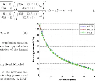
µ = 0.01, 0.05, 0.1 and 0.5 [8]. Comparison between predicted values of forming pressure and those of Ref. [8] for various friction coefficients is shown in Fig. 4. As the forming pressure increased beyond yielding, the contact length between the die and the tube increased and the arc radius decreased. The results showed that the values of forming pressure had a very good agree-ment with the results of Ref. [8] and they are coin-cident with each other. From this figure, it is known that the effect of friction coefficient upon the forming pressure is not significant.
Fig. 4. Variation of forming pressure with arc radius for various frictions andr0= 20mm,t0= 2mm,R= 1. (Comparison between predicted values, continues line, and those of Ref. [8], dashed line)
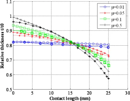
As the deformation progressed the tube thickness decreased. The maximum thinning occured at the arc segment. Changes in arc thickness with contact length for various friction coefficients are shown in Fig. 5. As seen in this figure, as the friction increases it causes greater corner thinning.
Effect of the friction coefficient upon the thickness variation along contact length is shown in Fig. 6. In this figure, predicted values and those of Ref. [8] are compared. For the frictionless case the wall thickness was uniform with a value of 0.82mm. A larger fric-tion coefficient will result in a smaller thickness or a larger strain at the arc segment, thus, it is more likely to lead to failure of the tube for a larger friction co-efficient at the die-tube interface. As the friction in-creases, the variation of the thickness increases. For
µ= 0.05, thickness varied from 0.74 to 0.89mm. There-fore, Thickness variation was 18%. While, forµ= 0.1, thickness varied by 25%, from 0.69 to 0.92.
Fig. 6. Comparison of predicted thickness variations (continues lines) and values of Ref. [8] (dashed lines), forr0= 30mm,t0= 2mm,R= 1.
Effects of the strain-hardening exponent, n= 0.14 and n = 0.24, on the forming pressure are shown in Fig. 7. The friction coefficient was maintained at 0.1. As seen in this figure, as the strain-hardening exponent increases, it causes greater corner thinning and lower forming pressure.
Fig. 7. Effect of the strain-hardening exponent on the forming pressure forr0= 30mm,t0= 2mm,R= 1.
In Fig. 8, the effect of the anisotropic coefficient on the forming pressure is shown. Anisotropic values are defined as the ratio of the strain in the width di-rection to that in the thickness didi-rection. Form this figure it is known that a larger anisotropic value can raise the forming pressure, in other words, it becomes more difficult to deform the tube to a desired corner radius.
Fig. 8. Effect of the anisotropic value on the forming pressure forr0= 30mm,t0= 2mm,µ= 0.05.
4. Conclusions
An analytical model was developed to study the ef-fect of the various process parameters on the thick-ness distribution and forming pressure for circular long anisotropic tube hydroforming in a square cross-section die. By using the thickness variation in two extreme cases of friction between tube and die wall, no fric-tion and sticking fricfric-tion, thickness variafric-tion in the case of friction was determined in the model. It was shown that anisotropic value has no influence on thick-ness variation of the formed tube in plane strain state and the forming pressure will increase when anisotropic value increases.
References
[1] J. Chen, Z. Xia, S. Tang, Corner fill modeling of tube hydroforming. Proceedings of the ASME, Manufacturing in Engineering Division, 11 (2000) 635-640.
[2] G. Kridli, L. Bao, P. Mallick, Two-dimensional plane strain modeling of tube hydroforming. Pro-ceedings of the ASME, Manufacturing in Engineer-ing Division, 11 (2000) 629-634.
[4] F. Vollertson, M. Plancak, On the possibilities for the determination of the coefficient of friction in the hydroforming of tubes. J. Mater. Process. Technol., 1125/1126 (2002) 412-420.
[5] G.T. Kridli, L. Bao, P.K. Mallick, Y. Tian, Inves-tigation of thickness variation and corner filling in tube hydroforoming, J. Mater. Process. Technol., 133 (2003) 287-296.
[6] G. Liu, S. Yuan, B. Teng, Analysis of thinning at the transition corner in tube hydroforming, J. Mater. Process. Technol., 177 (2006) 688-691.
[7] Y.M. Hwang, W.C. Chen, Analysis and finite ele-ment simulation of tube expansion in a rectangular cross-sectional die, Proceedings of the Institution of Mechanical Engineers, Part B: J. Eng. Manufact., 217 (2003) 127-135.
[8] Y.M. Hwang, W.C. Chen, Analysis of tube hydro-forming in a square cross-sectional die. Int. J. Plas-ticity., 21 (2005) 1815-1833.
[9] J.H. Orban, S.J. Hu, Analytical modeling of wall thinning during corner filling in structural tube hy-droforming, J. Mater. Process. Technol., 194 (2007) 7-14.
[10] J.E. Miller, S. Kyriakides, A.H. Bastard, On bend-stretch forming of aluminum extruded tubes I: ex-periments, Int. J. Mech. Sci. 43 (2001) 1283-1317.
[11] J.E. Miller, S. Kyriakides, E. Corona, On bend-stretch forming of aluminum extruded tubes II: analysis, Int. J. Mech. Sci., 43 (2001) 1319-1338.
[12] E. Corona, A simple analysis for bend-stretch forming of aluminum extrusions, Int. J. Mech. Sci., 46 (2004) 433-448.
[13] Y. Guan, F. Pourboghrat, Fourier series based finite element analysis of tube Hydroforming-generalized plane strain model, J. Mater. Process. Technol., 197 (2008) 379-392.
[14] Y. Guan, F. Pourboghrat, W. Yu, Fourier series based finite element analysis of tube hydroforming-an axisymmetric model, Eng. Computations., 23 (2008) 697-728.
[15] L.M. Smith, J.J. Caveney, T. Sun, Fundamen-tal concepts for corner forming limit diagrams and closed-form formulas for planar tube hydroforming analysis, J. Manufact. Sci. Eng., 128 (2006) 874-883.
[16] L.M. Smith, T. Sun, A non-finite element ap-proach for tubular hydroforming simulation featur-ing a new stickfeatur-ing friction model, J. Mater. Process. Technol., 171 (2006) 214-222.
[17] C. Yang, G. Ngaile, Analytical model for planar tube hydroforming: Prediction of formed shape, corner fill, wall thinning, and forming pressure, Int. J. Mech. Sci., 50 (2008) 1263-1279.