https://doi.org/10.5194/gi-8-241-2019
© Author(s) 2019. This work is distributed under the Creative Commons Attribution 4.0 License.
Development of a new distributed hybrid seismic and electrical data
acquisition station based on system-on-a-programmable-chip
technology
Qisheng Zhang1, Wenhao Li1, Feng Guo1, Zhenzhong Yuan1, Shuaiqing Qiao1, and Qimao Zhang2 1School of Geophysics and Information Technology, China University of Geosciences (Beijing), Beijing, China 2Institute of Electronics, Chinese Academy of Sciences, Beijing, China
Correspondence:Wenhao Li ([email protected]) Received: 1 April 2019 – Discussion started: 26 April 2019
Revised: 25 July 2019 – Accepted: 26 July 2019 – Published: 13 September 2019
Abstract. In the past few decades, with the continuous ad-vancement of technology, seismic and electrical instruments have developed rapidly. However, complex and harsh ex-ploration environments led to higher requirements and se-vere challenges for traditional geophysical exploration meth-ods and instruments. Therefore, it is extremely urgent to de-velop new high-precision exploration instruments and data acquisition systems. In this study, a new distributed seis-mic and electrical hybrid acquisition station is developed using system-on-a-programmable-chip (SoPC) technology. The acquisition station hardware includes an analog board and a main control board. The analog board uses a sig-nal conditioning circuit and a 24-bit asig-nalog-to-digital con-verter (ADS1271) to achieve high-precision data acquisition, while the main control board uses a low-power SoPC to en-able high-speed sten-able data transmission. We designed the data transmission protocol for the acquisition station and developed independently an improved low-voltage differen-tial signaling data transmission technology. What’s more, a method to enhance the precision of synchronous acquisition was studied in depth. These key technologies, which were developed for the acquisition station, were integrated into the SoPC of the main control board. Test results indicate that the synchronization precision of the acquisition station is better than 200 ns, and the maximum low-power data transmission speed is 16 Mbps along a 55 m cable. The developed acqui-sition station has the advantages of low noise, large dynamic range, low power consumption, etc., and it can achieve high-precision hybrid acquisition of seismic and electrical data.
1 Introduction
us-totellurics (CSAMT) method, the KMS-820 system from US company KMS, the GDP series multifunction electrical in-strument from US company Zonge, the eighth generation system V8 from Canadian company Phoenix, the distributed transient electromagnetic system GEOFERRET from Aus-tralian company WMC, and the ADU-08E system from Ger-man company Metronix – have been widely used. At the same time, relevant technical indicators of the surface elec-tromagnetic prospecting (SEP) system completed by the In-stitute of Geology and Geophysics in collaboration with the Institute of Electronics of the Chinese Academy of Sciences have reached an international standard (Chen et al., 2018, 2010; Di et al., 2013; Lin et al., 2014; Cheng et al., 2019). Modern seismic and electrical exploration instruments have reached a high level in terms of performance, stability, and industrialization, and they are being developed to achieve in-telligence and multi-functionality.
After several decades of resource exploration and exploita-tion, the energy resources on the surface of the Earth are diminishing, and oil and gas exploration has now encoun-tered a difficult stage in the world. Increasingly complex geological areas and severe exploration environments bring new challenges to traditional geophysical exploration meth-ods and instruments. Seismic and electrical exploration are the two most common geophysical methods currently used for prospecting. Seismic exploration is used to probe great depths and is extremely precise and highly resolved. Hence, it is widely used in the oil and gas industry, groundwater and geothermal resource exploration, and urban underground pipeline detection. However, its use in mining regions with poorly defined strata leads to dramatic lateral signal varia-tions and low signal-to-noise ratios (SNRs). Electrical ex-ploration has been rapidly developed and adopted in mineral resource prospecting, engineering surveys, and environmen-tal surveys. However, these techniques are not sufficient to research the fine ground structures because of limitations in vertical resolution of electrical exploration.
To make better use of various exploration methods, so as to reduce the ambiguity of the solution by the joint inver-sion of seismic and electrical methods, an integrated seis-mic and electrical hybrid acquisition technology is proposed. High-resolution hybrid seismic and electrical data acquisi-tion, high-precision synchronizaacquisi-tion, and high-speed data transmission under low-power conditions are big challenges.
US company Altera Corporation first introduced system-on-a-programmable-chip (SoPC) technology in 2000. A SoPC is a flexible and highly efficient system-on-a-chip (SoC) so-lution which integrates functional modules required by the system, such as a processor, I/O interface, hardware accel-erator, memory, etc., into a field-programmable gate array (FPGA) device to form a programmable SoC (Astarloa et al., 2005). A SoPC provides developers with a flexible design ap-proach with several advantages, such as low power consump-tion, easy upgrades and modifications, and both its hard-ware and softhard-ware are programmable (Zhang et al., 2012). In this study, SoPC technology is used to design a new hybrid seismic and electrical acquisition station. The advantages of SoPC technology improve the overall performance of the ac-quisition station.
2.2 Components of the distributed telemetry data acquisition system
The distributed telemetry data acquisition system mainly consists of sensors, acquisition stations, power stations, in-terconnection stations, a central station, and communication cables. Figure 1 shows a block diagram of the system in which sensors and acquisition stations form the front-end ac-quisition device, acac-quisition stations, and power stations are connected by cables, while interconnection stations and the central station, as well as the interconnection stations them-selves, are connected by optical fibers. Power stations and in-terconnection stations power the acquisition stations through power over Ethernet (PoE) and simultaneously carry out ac-quisition data transfer. The central station monitors the op-eration of the entire acquisition system and performs data recovery (Wang, 2010).
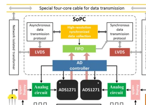
2.3 Overall framework of the new distributed hybrid seismic and electrical data acquisition station based on SoPC technology
high-Figure 1.Block diagram of the distributed telemetry data acquisition system. AS, acquisition station; PS, power station; IS, interconnection station; CS, central station.
precision clock source of the SoPC. The SoPC controls the ADS1271 through the serial peripheral interface (SPI) proto-col, and uses the synchronization signal of the ADS1271 to realize synchronous data acquisition of each channel. At the same time, we know that the data of the delta-sigma ADC (analog to digital converter) that just started to collect is unre-alistic. We performed corresponding operations during data processing to ensure the authenticity and validity of the data. SoPC uses FIFO (“first in, first out”) to buffer data, avoiding the frequent interruption of ADC work. Analog signal output by sensors (detectors or electrodes) is passed through sig-nal conditioning circuits for filtering, amplification, etc., and then is input into the ADS1271 to generate a digital signal. The data can be further filtered by the digital filter and syn-chronized with a high precision; it is then transmitted to the corresponding power station using Manchester encoding and custom data transmission protocols, as well as the indepen-dently developed low-voltage differential signaling (LVDS) low-power data transmission technology. The acquisition sta-tion developed in this study has the following characteris-tics: (1) a single station integrates high-precision acquisition channels of seismic and electrical data and (2) key technolo-gies of the developed acquisition station are the efficient in-tegration of different functions in a single SoPC.
3 Key technologies of the new distributed hybrid seismic and electrical data acquisition station 3.1 Hardware circuit design of the data acquisition
station
The hardware circuit of the acquisition station is composed of an analog board and a main control board. The analog board is mainly used for signal acquisition, conditioning, and high-precision analog-to-digital conversion. The main con-trol board achieves the concon-trol of each unit in the analog board as well as data encoding and transmission.
Figure 2.The overall structure of the data acquisition station.
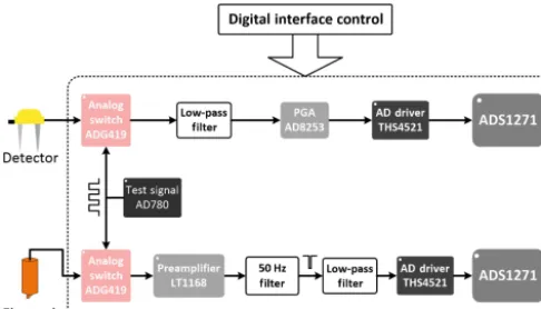
Figure 3.Block diagram of the analog board of the data acquisition station.
and subtract the signal through the band-pass filter from that of the all-pass circuit using the fourth operational amplifier to achieve filtering of the 50 Hz utility frequency signal. An-other difference between seismic and electrical channels is the low-pass filter (LPF) parameter. In the seismic channel, the cutoff frequency of the passive LPF is 1.2 kHz and the cutoff frequency of the active LPF in the electrical channel is 3.4 kHz.
The voltage of the power station continuously reduces as it supplies power to multiple acquisition stations in a PoE-like manner, and as a result the voltage entering the acquisition stations varies from 22 to 48 V (determined by the position of each acquisition station). Since the voltages required for the analog board are±5 V and 3.3 V, a PWB4812MD DC-DC chip is used to first convert the input voltage to 12 V, then a TMR3-1221WI conversion chip and PTH08080W switched-mode power supply are used to convert 12 V to±5 and 3.3 V, respectively.
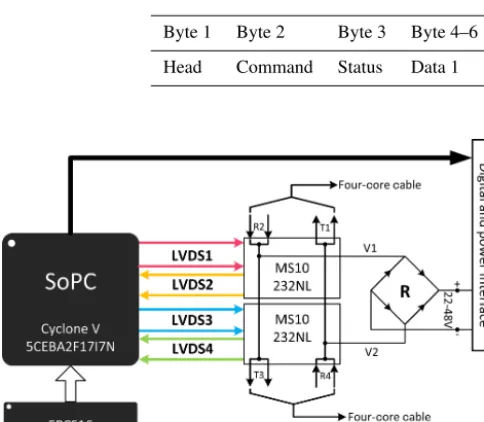
The main control board of the acquisition station is pri-marily composed of the SoPC, 5CEBA2F17I7N, and its configuration chip, EPCS16. Figure 5 shows a block di-agram of the main control data transmission board. The 5CEBA2F17I7N chip is a Cyclone V series FPGA, whose total power consumption compared with the previous gener-ation has dropped by 40 % due to the 28 nm low-power pro-cess technology. The main control board uses four pairs of LVDS differential pins on the SoPC and two network isola-tion transformers, MS10232NL, for data transmission. The advantages of using differential signaling include low power consumption, low bit error rate, low crosstalk, and low noise. (R2, T1) and (R4, T3) are two pairs of transceivers, while V1 and V2 are two lines with a common-mode voltage that are trapped between (R2, T3) and (T1, R4), respectively. The dif-ference in value between the two is recognized by the bridge rectifier circuit, R, as a positive or negative voltage and then transmitted to the analog board for voltage conversion. The digital and power interfaces are used for communication and
signal. To solve this problem, this study uses the Manchester encoding technique which represents 0 and 1 based on volt-age transitions. Manchester encoding makes it easier to ex-tract a synchronized clock from the signal, and at the receiv-ing end it constantly aligns the valid edges usreceiv-ing a method for oversampling. This can reduce the hardware circuit de-sign, as well as the system power consumption, and simulta-neously avoid the problem of burrs along the data transition edges.
The encoding module at the transmitting end first converts the 8-bit parallel data in units of bytes into a bit stream out-put by bit and then transmits the encoded serial data in which “01” is used to represent the binary “0” and “10” is used to represent the binary “1”. The data transmission rate on the transmission line is 16.384 Mbps during the process, mean-ing that the required encodmean-ing clock should be 32.768 MHz. At the receiving end, to detect effective transitions in the Manchester encoded data stream and extract the synchronous clock, a method for oversampling is adopted. The sampling clock frequency used by the decoding module is 8 times that of the data transmission rate, and data sampling, decoding, and shift and byte synchronization are carried out. Through this method of encoding and/or decoding, serial binary data transmission is achieved in the true sense that is enabled only by solving the problems of byte synchronization and frame synchronization. When the receiving end starts to receive one frame of data after receiving the preamble, it first receives the frame header that contains information on the data length of this frame, it then receives data according to the length de-fined in the frame header, and finally restores this data to parallel data (in bytes).
Figure 4.50 Hz filter circuit schematic.
Table 1.Cell format of data frames in an acquisition station.
Byte 1 Byte 2 Byte 3 Byte 4–6 Byte 7–9 Byte 10–12 Byte 13–15 Byte 16 Head Command Status Data 1 Data 2 Data 3 Data 4 CRC
Figure 5. Block diagram of the main control data transmission board.
Data in the acquisition station can be transmitted in two modes: synchronous transmission and asynchronous trans-mission. As shown in Fig. 6, the asynchronous transmis-sion mode is adopted when reporting status information and uploading data from the slave power station to the mas-ter power station, while synchronous transmission mode is adopted when uploading data and status information from the acquisition station to the slave power station or the mas-ter power station, as well as when receiving control com-mands from the master power station (Li, 2018). During synchronous acquisition, the master power station sends out empty data frames. Each acquisition station then decodes these empty data frames, translates them to their correspond-ing unit, writes the data in the FIFO to the correspondcorrespond-ing po-sition of this unit, then sets the unit status byte to 1 and
com-Figure 6.Schematic diagram of synchronous data acquisition and asynchronous communication of the data acquisition station.
mand byte to 0x0F, and finally recalculates the CRC for this unit. In asynchronous transmission, the received data only need to be re-encoded and sent out without modifying the data frame. Therefore, acquisition stations in asynchronous transmission only undertake the task of data transfer between the power stations.
3.3 High-precision synchronous data acquisition technology
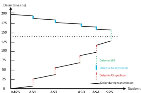
de-Figure 7.Schematic of the round-trip transmission delay in data frames between two power stations (MPS, master power station; AS, acquisition station; SPS, slave power station).
lay due to time spent in acquisition stations in the direction of asynchronous transmission. Figure 7 shows the delay of data frames when transmitted back and fourth between the slave power station and the master power station when there are four acquisition stations in between.
In this study, high-precision synchronization is realized through controlling the acquisition stations by sending syn-chronous acquisition commands from the master and slave power stations. The master power station sends one frame of data to the acquisition stations (in synchronous acquisition mode) and the acquisition station starts to decode the data frame after receiving it. If a synchronous acquisition com-mand frame is recognized, the acquisition station forwards the data frame to the next acquisition station and starts timing simultaneously. When the same acquisition station receives the synchronous acquisition command frame again (which is returned from the slave power station in asynchronous trans-mission mode), it stops timing. Hence, if the timed duration at theNth acquisition station in the acquisition chain isTN, as shown in Fig. 8,
TN=TA+TS+Tsl, (1)
Td=TS−TA, (2)
TN+Td=2TS+Tsl, (3)
TS= 1
2(TN+Td−Tsl), (4)
where TA, TS, and Tsl are the time durations required by the synchronous acquisition command frame in the asyn-chronous transmission process, in the synasyn-chronous acquisi-tion process, and in forwarding from the slave power staacquisi-tion, respectively.Tdis the time difference between synchronous acquisition and asynchronous transmission. Since the time spent transmitting data over cables is the same in both di-rections for synchronous acquisition and asynchronous trans-mission,Tdcan represent the sum of the processing time dif-ferences between the two different data transmission modes
Figure 9.Synchronization precision test results of acquisition sta-tions.
in the acquisition stations. Assuming that in thejth tion station, the time consumed by the synchronous acquisi-tion process istjand the time consumed by the asynchronous transmission process istj0 – if there are a total ofM acquisi-tion staacquisi-tions on an acquisiacquisi-tion chain – then
Td= M
X
j=N+1
(tj−tj0), (5)
TS= 1 2
M
X
j=N+1
(tj−tj0)+TN−Tsl !
. (6)
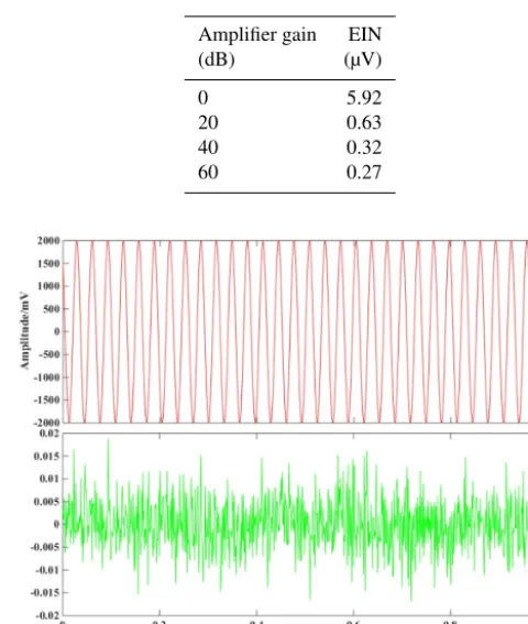
Figure 10.Distribution of the EIN of a data acquisition station.
Figure 11.Spectrogram of the EIN in the 0–1 kHz band.
4 Summary of acquisition station test and performance 4.1 Equivalent input noise test
The equivalent input noise (EIN) of the acquisition station, which determines the instrument’s ability to resolve weak signals, consisted of a variety of noises. During the test, a 1 ktest resistor was connected to the analog-signal input terminal and the sampling rate of ADS1271 was configured as 1000 samples per second. When the front-end gains of both channels were set to 0, 20, 40, and 60 dB, 10 s of data sampling was performed at each station. Furthermore, ac-quired data were analyzed with MATLAB. Figure 10 shows the distribution of the EIN of a data acquisition station with a sampling rate of 1000 SPS and gain of 60 dB; the noise distri-bution is similar to Fig. 10 at other gains. Figure 11 shows the spectrum of the equivalent input noise in the 0–1 kHz band when the gain of the acquisition station is 0 dB.
The calculation results of EIN at different gains for the acquisition station are shown in Table 2.
Table 2.Results of EIN tests.
Amplifier gain EIN (dB) (µV)
0 5.92
20 0.63 40 0.32 60 0.27
Figure 12.Time domain waveform of each channel during the first crosstalk test (red: seismic channel; green: electrical channel).
4.2 Channel crosstalk test
Since there are two channels on the analog board, they will inevitably cause mutual interference. During the first test, the electrical channel was short-circuited and a sine wave with a frequency of 31.25 Hz and a peak-to-peak value of 4 V was input into the seismic channel, with the gain set to 1. Data ac-quisition was performed at different sampling rates and then MATLAB was used to obtain waveform diagrams, as shown in Fig. 12. Then, the seismic channel was short-circuited and a sine wave with a frequency of 1 kHz and a peak-to-peak value of 2.5 V was input into the electrical channel. After performing fast Fourier transform (FFT) processing for the data, it was found that at a frequency of 1 kHz the relative power (8 dB) of the electrical channel is much larger than that of the noise (−128 dB) in the seismic channel in Fig. 13, indicating that the level of crosstalk between the channels satisfies design requirements.
4.3 Summary of performance indicators
Figure 13.Spectral characteristics of signals in seismic and electri-cal channels.
Table 3.Acquisition station main performance indicators.
ADC resolution 24 bits
Sampling rates 1,2,4,and 8 kHz
Preamplifier gain 0 to 60 dB in 20 dB steps
Synchronization accuracy <200 ns
Maximum input signal 2.5 V peak at gain 0 dB
EIN 0.61 µV at 1 kHz at gain 20 dB
Total dynamic range 107 dB at gain 0 dB
Power consumption 230 mW
Acquisition station interval 55 m (maximum)
Supply voltage 18–72 VDC
Channel crosstalk −109 dB at gain 0 dB
Common mode rejection ratio >101 dB
Total harmonic distortion <0.0005 %
Data transmission speed 16 Mbps
Operating temperature −30 to+70◦C
5 Conclusions
Based on SoPC technology, this study develops a new type of distributed seismic and electrical hybrid acquisition station. The paper mainly explores the following technical aspects:
1. High-precision integrated seismic and electrical acqui-sition technology.Different front-end signal condition-ing circuits were designed based on the characteristics of seismic and electrical signals and a 24-bit delta-sigma (1-6) ADC was used to achieve high-precision data ac-quisition.
2. High-speed low-power data transmission technology.A dedicated data transmission protocol and data frame for-mat were designed. In addition, based on the improved LVDS data transmission technology independently de-veloped, functions of synchronous acquisition and asyn-chronous transmission were developed according to ac-tual needs to enable low-power data transmission at a speed of 16 Mbps along a 55 m cable.
Data availability. The schematic of the 50 Hz filter circuit is avail-able upon request ([email protected]).
Author contributions. QisZ and WL developed the required cir-cuits. FG and SQ developed the required software. ZY and QimZ performed the tests.
Competing interests. The authors declare that they have no conflict of interest.
Acknowledgements. We would like to thank the reviewers for help-ing us to improve the paper. We would also like to thank Editage (http://www.editage.cn, last access: 14 August 2019) for their En-glish language editing services.
Financial support. This research has been supported by the Natural Science Foundation of China (grant nos. 41574131 and 41204135), the National “863” Program of China (grant nos. 2012AA061102 and 2012AA09A20102), the National Major Scientific Research Equipment research projects of China (grant no. ZDYZ2012-1-05-01), and the Fundamental Research Funds for the Central Univer-sities of China (grant no. 2652015213) and the China Scholarship Council.
Review statement. This paper was edited by Valery Korepanov and reviewed by three anonymous referees.
References
Astarloa, A., Bidarte, U., and Lazaro, J.: Multiprocessor SoPC-Core for FAT volume computation, Microprocess. Microsy., 29, 421– 434, 2005.
Chen, K., Jin, S., and Deng, M.: Multifunction waveform generator for EM receiver testing, Geosci. Instrum. Method. Data Syst., 7, 11–19, https://doi.org/10.5194/gi-7-11-2018, 2018.
Cheng, S., Deng, M., Wang, M., Jin, S., Zhang, Q., and Chen, K.: A wireless monitoring system for a high-power borehole-ground electromagnetic transmitter, Geosci. Instrum. Method. Data Syst., 8, 13–19, https://doi.org/10.5194/gi-8-13-2019, 2019. Di, Q. Y., Fang, G. Y., and Zhang, Y. M.: Research of the
Surface Electromagnetic Prospecting (SEP) system, Chinese J. Geophys.-Ch., 11, 3629–3639, 2013.
Guo, J., Liu, G. D., Xu, S. H., and Liu, N.: Computer network-based novel digital seismograph with mega-channel level, Ref.No:CN102628957A, Chinese Patent, 2012.
Huang, X. L. and Yu, J. S.: Numerical analysis for the characteris-tics of SN338 digital seismic instrument, Chinese J. Geophys.-Ch., 37, 597–602, 1994.
Li, S. H.: Research on Data Transmission Technology in Seismic and Electrical Distributed Acquisition Stations, China University of Geosciences (Beijing), Beijing, 3–26, 2018.
Lin, J., Fu, L., Wang, Y. Z., Xu, J., Ji, Y. J., and Yang, M. M.: Devel-opment of sensor used for grounded electrical source air-ground transient electromagnetic detection, Journal of Jilin University (Engineering and Technology Edition), 3, 889–894, 2014. Liu, G. D.: Developing earth exploration technology in three
dimen-sion, improving the performance of instrument for geosciences, Chinese J. Geophys.-Ch., 56, 3607–3609, 2013.
Liu, G. D.: Promote the innovation of geophysical methodology, and lead the future of exploration apparatus technology, Chinese J. Geophys.-Ch., 60, 4145–4148, 2017.
Mrmureanu, A., Ionescu, C., and Cioflan, C. O.: Advanced real-time acquisition of the Vrancea earthquake early warning system, Soil Dyn. Earthq. Eng., 31, 163–169, 2011.
Qiao, S., Duan, H., Zhang, Q., Zhang, Q., Li, S., Liu, S., Liu, S., Wang, Y., Yan, S., Li, W., and Guo, F.: Development of high-precision distributed wireless microseismic acquisition stations, Geosci. Instrum. Method. Data Syst., 7, 253–263, https://doi.org/10.5194/gi-7-253-2018, 2018.
Van, D., Spitzer, R., and Green, A.: Design and application of a towed land-streamer system for cost-effective 2-D and pseudo-3-D shallow seismic data acquisition, Geophysics, 66, 482–500, 2001.
Wang, H. S.: Key Problem Research on Data Transmission of Large-scale Seismic Acquisition and Recording System, PhD thesis, Tsinghua University, Beijing, 40–62, 2010.
Wang, Q., Deng, M., and Zhang, Q. S.: High-Precision synchronous implementation during seismic data acquisition, Adv. Mat. Res., 171-172, 764–768, 2011.
Zhang, L. H.: Study on Data Transmission Techniques Based on Re-lay Ethernet in Seismic Exploration Using Vibroseis, PhD thesis, Jilin University, Jilin, 30–50, 2007.
Zhang, Q. S., Deng, M., Yang, K. P., Chen, K., Wang, M., and Sun, Z. C.: Application of SoPC on High-precision Geoelectric Data Acquisition System, Geoscience, 26, 1306–1311, 2012. Zhang, Q. S., Deng, M., Guo, J., Luo, W. B., and Wang, Q.:
Development of a new seismic-data acquisition station based on system-on-a-programmable-chip technology. Ann. Geophys., 56, 1–9, https://doi.org/10.4401/ag-6309, 2013.
Zhang, Q. S., Jiang, J. J., Zhai, J. H., Zhang, X. Y., Yuan, Y. J., and Huang, X. W.: Seismic Random Noise Attenuation Us-ing Modified Wavelet ThresholdUs-ing. Ann. Geophys., 59, 1–10, https://doi.org/10.4401/ag-7097, 2016.