Please cite this article as: S. Mahmoudzadeh, H. Mojallali, N. Pourjafari, An Optimized PID for Capsubots using Modified Chaotic Genetic Algorithm, International Journal of Engineering (IJE), TRANSACTIONS C: Aspects Vol. 27, No. 9, (September 2014) 1377-1384
International Journal of Engineering
J o u r n a l H o m e p a g e : w w w . i j e . i r
An Optimized PID for Capsubots using Modified Chaotic Genetic Algorithm
S. Mahmoudzadeh, H. Mojallali*, N. Pourjafari
Electrical Engineering Department, Faculty of Engineering, University of Guilan
P A P E R I N F O
Paper history: Received 07 January 2014
Received in revised form 29 April 2014 Accepted 22 May 2014
Keywords:
Capsubot Chaos
Genetic algorithm PID controller Optimization
A B S T R A C T
This paper proposes a design for a mesoscale capsule robot which can be used in gaining diagnostic data and delivering medical treatment in inaccessible parts of the human body. After modeling the capsule robot system and determining its transfer function, an approach is presented for the capsule robot to control it: A PID-controlled closed-loop approach. A modified chaotic genetic algorithm is proposed in order to optimize the coefficients of the PID controller. Then, simulations are conducted to demonstrate the results for the proposed approach. Finally, the results are compared with those of similar works in the literature.
doi: 10.5829/idosi.ije.2014.27.09c.07
NOMENCLATURE
M (Kg) The weight of the capsule body u (N) Applied force by the piezoelectric device
m (Kg) The weight of the inner mass a (m) Half-length of the capsule length
x1(t) (m) The position of the capsule body G(S) Open-loop transfer function of the capsubot
x2(t) (m) The position of the inner mass K(S) Transfer function of the PID controller
t1, …, t4(s) Duration of steps 1 through 4 T(S) Closed-loop transfer function of the capsubot
μ1k kinetic friction coefficient between the capsule shell and the outside environment H(S) Transfer function of the transducer block
μ2k kinetic friction coefficient between the capsule shell and the inner
mass MO
The maximum overshoot of the impulse response of the closed-loop transfer function of the capsubot
g (m/s2) Acceleration to the gravity Ts The settling time of the impulse response of the
closed-loop transfer function of the capsubot
1. INTRODUCTION1
A capsubot (capsule robot) is a mesoscale robot which has recently attracted extensive attention in the medical research community. Studies have shown that capsubots are of potential application in medical diagnosis and treatment [1-3]. A capsubot is an autonomous robot which can explore inaccessible parts of the body; For instance, in gastrointestinal endoscopy, and especially
1
*Corresponding Author’s Email: [email protected] (H. Mojallali)
for the small intestine which is challenging to be accessed by means of conventional methods. There are mainly two types of capsubots: legged capsubots, and legless capsubots. In the former, the capsule has an external mechanism to drive the capsule [4, 5]. The drawbacks of this method are its complexity, the high cost of the structure, and the likelihood of causing damage and pain to patients as a result of the legs of the capsubot moving along the stomach and the intestine [6]. The legless capsubot, on the other hand, has a simple driving mechanism based on internal propulsion
(between the capsule shell and the inner mass), and
friction [7, 8].
Most of the literature on capsubots is focused on the design of the capsubot structure, while the optimization and control of capsubots is neglected. The analysis and the tracking issue of capsubots studied in [9]. A predictive controller model for capsubot’s time delay was presented in [10], and the motion generation strategy for capsubots has been described in [7]. Also, the wireless control of an endoscopic capsule robot has been studied in [11, 12].
Evolutionary algorithms such as Genetic Algorithm (GA) and Particle Swarm Optimization (PSO) have been widely used in the literature in many different applications [13-15]. In this work, GA is used to optimize the behavior of the capsubot. GA is inspired from natural reproduction and evolution, and is one of the most powerful methods in metaheuristic optimization. Similar to many of the metaheuristic methods in the literature, the basic GA may result in a local minimum. Hence, the algorithm stops before converging to the global minimum point. A modified chaotic GA is presented in this paper in order to overcome this problem and also increase the convergence speed [16] and enhance the performance of the algorithm for our application.
The present paper also investigates the tuning of the coefficients of the PID controller. The rest of the paper is organized as follows: In section 2, the dynamics of the capsubot is presented. The proposed modified chaotic genetic algorithm and the associated cost function of the proposed dynamic model are described in Section 3. Next, the analysis and the optimization of the capsubot followed by computer simulations and results are presented in Section 4. Finally, conclusions are given in Section 5.
2. The CAPSUBOT DYNAMIC MODEL
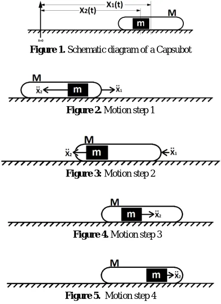
The capsubot consists of two main parts: capsule shell M and the inner mass (moving part) m, where x1 and x2 are positions of M and m respectively. A schematic diagram of a capsubot is depicted in Figure 1.
2. 1. Motion Generation Strategy The motion generation of a capsubot is based on the propulsion force between the capsule shell and the inner mass. The inner mass must shake in a certain manner so that the capsule shell moves in the desired trajectory. In the case of a one dimensional movement, the inner mass should shake in fast and slow stages. For the purpose of this work, we propose a four-step motion [17]:
Step 1: 0<t<t1, the acceleration vector of the inner mass is to the left with a high amplitude, and the acceleration vector of the capsule is to the right (Figure 2).
Figure 1. Schematic diagram of a Capsubot
Figure 2. Motion step 1
Figure 3: Motion step 2
Figure 4. Motion step 3
Figure 5. Motion step 4
Step 2: t1<t<t2, the acceleration vector of the inner mass is to the left with low amplitude, and the acceleration vector of the capsule is also to the left (Figure 3). Step3:t2<t<t3, the acceleration vector of the inner mass is to the right with a low amplitude, and the capsule remains stationary (Figure 4).
Step 4:t3<t<t4, the acceleration vector of the inner mass is to the right with a very low amplitude, and the capsule remains stationary (Figure 5).
In the above steps, t2 is predefined arbitrarily by the designer. t3 and t4 are calculated as below:
t1 = t2/2, t3 = 2t2. (1)
t4 = 2t2 + (2t22 + 8a/β) 1/2. (2)
Note that the effect of step 1 is implicitly incorporated in step 2 [17]. In Equation (2), a is the half-length of the capsule shell, and β is defined as below:
β= μ(M+ m)g/m. (3)
2. 2. Capsubot Transfer Function Using Newton’s second law for the external capsule and the inner mass, we obtain [9, 18]:
Mẍ1+μ1k(M + m) × sgn(ẋ1) - μ2k mg × sgn(ẋ2-ẋ1) = u. (4)
where M and m are the mass of the capsule shell, and the inner mass, respectively; u is the propulsion force between the shell and the inner mass generated by a piezoelectric element; g the acceleration due to gravity; μ 1kthe kinetic friction coefficient between the capsule shell and the outside environment, and μ2k the kinetic friction coefficient between the capsule shell and the inner mass. Rewriting Equation (5) will result in:
μ2km g× sgn(ẋ2-ẋ1) = - u - m ẍ2 (6)
Substituting Equation (6) in Equation (4):
M ẍ1 + μ1k (M + m) g× sgn (ẋ1) - (- u - m ẍ2) = u. (7)
→Mẍ1 + μ1k ( M + m ) g× sgn (ẋ1) + mẍ2 = 0 (8)
For the ease of calculation and considering that for small values of ẋ1:
sgn(ẋ1) ≈ẋ1 (9)
Then, Equation (8) will be simplified to:
Mẋ1 + μ1k (M + m) g×ẋ1 + mẍ2≈ 0. (10)
Assuming that μ2k is small, Equation (5) could be
rewritten as below:
mẍ2(t) = - u(t). (11)
Applying Laplace transformation to Equations (10) and (11):
MS2X
1(S) + μ1k (M + m) gSX1(S) + m S2 X2(S)=0. (12)
U(S) = - mS2X2(S) (13)
Substituting X2(s) from Equation (13) in Equation (12), the capsubot transfer function can be written as:
(14)
The block diagram of an open-loop capsubot system is shown in Figure 6.
Consider a PID controller with KP, KI and KD as
proportional, integrative, and derivative coefficients, respectively. A PID controller transfer function can be written as:
K(S) = KP + KI/S + KD S [1/(TF S +1)]. (15)
In practical applications, since an increment in the derivative factor of controller might lead to system instability, we use a filter in the derivative part of the controller with a sampling time of TF. The block
diagram of a closed-loop PID controlled capsubot is shown in Figure 7.
According to Equations (14) and (15), the closed-loop PID controlled transfer function of the capsubot can be written as:
Figure 6. An open-loop capsubot system
Figure 7. A closed-loop PID controlled capsubot block diagram
T(S) = C(S) / R(S) = K(S).G(S) / [1+K(S).G(S)]. (16)
In the control system above, R(t) and C(t) are the input and output of the whole system, respectively. C(t) represents the capsubot's trajectory, and R(t) represents the desired velocity which must be tracked by the capsubot and is defined by the user. The transducer block (H(S)) transforms the position of capsubot into its velocity. A simple derivative block can perform this task. The closed loop control system feeds back the velocity of capsubot (V1(t)) and compares it to the desired velocity signal. Then, the error signal (e(t)) is applied to the well-tuned PID controller, so that the PID controller determines the force signal needed to be applied to the piezoelectric element in order to minimize the error between the velocity of the capsubot and the desired velocity.
3. MODIFIED CHAOTIC GENETEIC ALGORITHM
The transfer function of the capsubot has poles near the origin. Therefore, the basic GA might be stuck in a relative minimum and/or output an infinite answer for the problem, and it will be terminated before reaching an optimal solution. A regular random disturbance might help the algorithm escape from these local minima and find the global minimum. Also, in order to prevent the algorithm from producing infinite solution values, in all parts of the modified GA, a selective mechanism governs. Thus, after each iteration of the algorithm, only those solutions that make a better cost value are accepted. The solutions that have a worse cost value are neglected. Therefore, the modified chaotic GA does not produce infinite solution values and has a higher chance of finding the global optimum.
rises from the extreme complexity of such systems and
huge number of variables which makes it so sensitive that even a very small change in its parameter values or initial states can cause a huge change in system’s output. Chaos is used in order to have the modified genetic algorithm suppress local minimum points.
Consider the closed-loop PID controlled system introduced in section 2. In order to improve the behavior of the capsubot the settling time of the impulse response (Ts) and the Maximum Overshoot of the impulse
response (MO) are minimized during the optimization. Z is defined as the Cost function which expresses the impressions of these properties by allotting weight coefficients to them (W1 and W2):
Z = W1 * MO+ W2* Ts. (17)
The algorithm makes an effort to find the global minimum point of the function, Z = f (KP, KI, KD).
According to the transfer function of the capsubot, f (KP,
KI, KD) might be a complex 3D graph with many
relative minima and one global optimum. In practice, it is observed that not only chaos helps the algorithm to escape from relative minima, but it also increases the convergence speed to the absolute minimum. Consider a chaotic variable Xn and the following chaotic sequence:
Xn+1 = C * Xn (1 - Xn), 0 <X0 <XnMax= 1. (18)
where, C is a coefficient usually set at about 0.4. The sequence above makes Xn chaotic. In other words, while
n increases, the chaotic sequence has the ability to generate a series of values between 0andXnMax=1, with
better statistical properties than usual random value generation methods. Since the chaotic sequence is sensitive to the initial value of X0, different values of X0
generate different values of Xn. Hence, for a specific
value of n, Xn is different for different amounts of X0,
i.e., Xn is chaotic. Note that, according to practical
results, C must decrease with the increase in number of the iterations of the chaotic genetic algorithm, in order to gain better results.
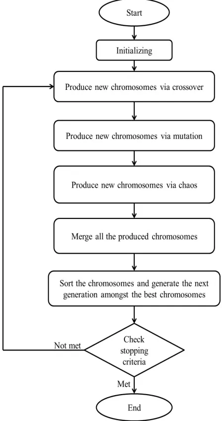
A flowchart of the proposed modified chaotic GA is presented in Figure 8. All parts of the flowchart are described as follows.
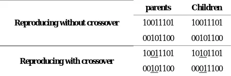
3. 1. Initializing In the initializing step of the algorithm, the parameters used in algorithm such as the number and range of the variables, number of iterations, population size, crossover percentage and mutation percentage are defined. Also, parameters related to the capsubot such as weight of the inner mass and the capsule body, length of the capsule, and the kinetic friction coefficient are determined in this step. After specifying the required parameters, the first generation of chromosomes are produced. In the modified GA presented in this paper, only finite and legitimately appropriate solutions are accepted. After the initializing step, the main loop of the algorithm begins.
TABLE 1. An example of crossover
Reproducing without crossover
parents Children
10011101 10011101
00101100 00101100
Reproducing with crossover
10011101 10101101
00101100 00011100
3. 2. Crossover After randomly producing the first generation in the initializing step, each pair of parents produces one pair of children. The crossover percentage determines the probability that the children are not identical to their parents (i.e., the opposite of the probability that parents reproduce themselves as children in the next generation). An example of producing children with crossover and producing children without crossover is given in Table 1.
3. 3. Mutation Mutation is performed to produce off springs with mutated genes. One of the genes in the chromosome of the parent is selected randomly and a new random value within the range of the problem space is assigned to this gene. Mutation helps the algorithm to find new chromosomes which may not be produced by crossover. The number of chromosomes in which mutation happens depends on the mutation percentage. Compared to the results of crossover, the results of mutation are uncommon. Therefore, a big mutation percentage might lead to data corruption. In this work the mutation percentage is 10%.
3. 4. Chaos In this part of the modified chaotic GA, the last set of new chromosomes is produced by chaos. In order to produce off springs using chaos, the genes in a chromosome are selected. Each one of these genes is assigned as initial value in a logistic function. Therefore, for each gene a chain of chaotic values is produced, which are used as genes for new chromosomes. Using chaos, any number of chromosomes can be produced in each iteration. In this work, 50% of the chromosomes are produced by chaos.
produced by each function are not distinctively different, therefore, the first method is used.
3. 6. Evaluation The final step in the algorithm is evaluation. In the evaluation step, the stopping criteria for the algorithm are checked. The stopping criteria can be defined as the elapsed time, number of iterations, reaching an expected cost value, etc. In this work we use the number of iteration as stopping criterion. If the stopping criteria are not satisfied, the algorithm will start the next iteration. Otherwise, it will stop and the best chromosome among the chromosomes of the last generation will be chosen as the final answer for the algorithm.
Figure 8.The modified chaotic genetic algorithm
TABLE 2. Simulation Parameters used for the capsubot
M [Kg] m [Kg] µ1k g [m/s2] a [m] t2 [s]
0.003 0.004 0.1 9.81 0.025 0.005
TABLE 3. PID Parameters
KP KI KD TF
41.61 99.97 0.12 0.86
TABLE 4. Parameters of capsubot used in [17] and [18]
M [Kg] m [Kg] µ1k g [m/s
2
] a [m] t2 [s]
0.003 0.004 0.3 9.81 0.005 0.024
TABLE 5. Comparing results with [17] and [18] Case Cycle Time (sec) Distance (cm) Speed (cm/sec)
This work 0.37 3.5 9.46
[14] 0.18 1.1 6.11
[16] 0.18 1.4 7.78
4. SIMULATION RESULTS
MATLAB® Simulink R2008b was used to simulate the PID closed loop controller, and the simulation was performed on a CORE i5 Intel, 2.3 GHz, with 4 GB of RAM. Next the results of this work were compared with those of others in the literature.
4. 1. Optimization Table 2 shows the parameters used in the simulation, which are close to those that can be used in practical applications according to the properties of intestine and stomach referred to in the literature [19]. The coefficients obtained for the PID controller after simulating the chaotic genetic algorithm represented in this paper are shown in Table 3.
4. 2. Comparison with Other Works Some of
the other works in the literature [17, 18] are selected to be compared with this work. The parameters of the capsubot in these works are close to those used in this work which are listed in Table 4. The distance that the capsubot traverses in one cycle and the duration of each cycle for each work is also shown in Table 5.
Figure 9. Desired capsubot velocity
Figure 10. Capsubot velocity
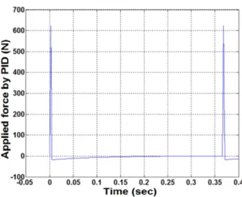
Figure 11. Applied force by PID to capsubot
Figure 12. Capsubot Trajectory
Figure 13. Trajectory of the capsubot for different cases in Table 6.
TABLE 6. Corruption percentages in the values of the parameters
Case m M a µ1k
1 3% -1% 3% -1%
2 -1% 0 2% -3%
3 -2% 3% 2% 2%
4 -4% -3% -1% 2%
5 1% -2% -3% 5%
6 1% -2% 2% 3%
7 1% 5% -4% 4%
8 0 -2% -2% -4%
9 3% -3% -2% 3%
10 1% -25 0 -3%
It can be seen that the duration of one cycle in this work is longer than those of [17, 18]. But, the distance that the capsubot traverses is more than those works. The speed of the capsubot shows considerable improvement of the proposed method in this work.
mass, the weight of capsule body, the kinetic friction coefficient and the capsule length were added randomly to them. Next, simulations were performed with the parameters achieved from the proposed algorithm. These simulations were performed for different cases of adding random error and the results for the capsule trajectory are shown in Figure 13. The percentage of added error to each parameter in each case is shown in Table 6.As in can be seen in Figure 13, fabrication error does not have a major effect on the behavior of the capsubot. In different cases of adding random error, the capsule body almost traverses the same trajectory and the error is negligible.
5. CONCLUSION
This paper developed a novel approach to design of a closed-loop control system with a PID controller for the capsubot. First, the transfer function of the capsubot was estimated. An appropriate cost function was chosen in order to minimize the error between the desired velocity and the capsubot velocity. Simulations were then performed to show the results, and the effectiveness of the proposed approach was demonstrated. Next, the results were compared with those of other works in the literature. It was seen that the speed of capsubot was more than that of similar works. It should be noted that the amount of required force was not limited in this work which should be considered as a limiting criterion in practical applications. Future work can include using other metaheuristic methods to design the controller, developing control approaches other than PID-based controllers, designing new motion profiles, reducing the size of capsubot and optimizing the required force. Also, implementation and fabrication of proposed models for capsubot in order to evaluate and test these methods are of value.
6. REFERENCES
1. MacFadyen, B. and Cuschieri, A., "Endoluminal surgery", Surgical Endoscopy, Vol. 19, No. 1, (2005), 1-3.
2. Schostek, S., Fischer, H., Kalanovic, D. and Schurr, M., "Microsystems in medicine-results of an international survey", Minimally Invasive Therapy & Allied Technologies, Vol. 14, No. 6, (2005), 360-368.
3. Dario, P., Hannaford, B. and Menciassi, A., "Smart surgical tools and augmenting devices", Robotics and Automation, IEEE Transactions on, Vol. 19, No. 5, (2003), 782-792.
4. Karagozler, M.E., Cheung, E., Kwon, J. and Sitti, M., "Miniature endoscopic capsule robot using biomimetic micro-patterned adhesives", in Biomedical Robotics and
Biomechatronics, The First IEEE/RAS-EMBS International Conference on, IEEE. (2006), 105-111.
5. Kósa, G., Shoham, M. and Zaaroor, M., "Propulsion of a swimming micro medical robot", in Robotics and Automation, 2005. ICRA 2005. Proceedings of the IEEE International Conference on, (2005), 1327-1331.
6. Dario, P., Stefanini, C. and Menciassi, A., Modeling and experiments on a legged microrobot locomoting in a tubular, compliant and slippery environment, in Experimental robotics ix., Springer. (2006), 165-174.
7. Li, H., Furuta, K. and Chernousko, F.L., "Motion generation of the capsubot using internal force and static friction", in Decision and Control, 45th IEEE Conference on,. (2006), 6575-6580. 8. Kim, B., Park, S., Jee, C.Y. and Yoon, S.-J., "An earthworm-like
locomotive mechanism for capsule endoscopes", in Intelligent Robots and Systems,.(IROS). IEEE/RSJ International Conference on, (2005), 2997-3002.
9. Liu, Y., Yu, H. and Yang, T., "Analysis and control of a capsubot", City, Vol. 10, (2008), 2-10.
10. Chen, W., Fang, M. and Yu, H., "Model predictive control applied into time delay capsubot system", in Intelligent Human-Machine Systems and Cybernetics,. IHMSC'09. International Conference on, IEEE. Vol. 1, (2009), 112-115.
11. Peng, D., Yao, S., J., Z. and Wang, L., "A wireless power management microsystem for endoscopic capsule robot," Bulletin of Advanced Technology Research, Vol. 5, (2011), 19-23.
12. Susilo, E., Valdastri, P., Menciassi, A. and Dario, P., "A miniaturized wireless control platform for robotic capsular endoscopy using advanced pseudokernel approach", Sensors and Actuators A: Physical, Vol. 156, No. 1, (2009), 49-58.
13. Daryabeigi, E., Fard, F.T.P. and Arab, G., "An optimal selection of induction heater capacitance by genetic algorithm considering dissipation loss caused by esr", in Optimization of Electrical and Electronic Equipment, OPTIM. 11th International Conference on, IEEE. (2008), 239-244.
14. Gholipour, R., Khosravi, A. and Mojallali, H., "Suppression of chaotic behavior in duffing-holmes system using back-stepping controller optimized by unified particle swarm optimization algorithm", International Journal of Engineering-Transactions B: Applications, Vol. 26, No. 11, (2013), 1299.
15. Deepa, S., Babu, S.R. and Ranjani, M., "A robust statcom controller using particle swarm optimization", International Journal of Engineering-Transactions B: Applications, Vol. 27, No. 5, (2013), 731.
16. Wu, T., Cheng, Y., Tan, J. and Zhou, T., "The application of chaos genetic algorithm in the pid parameter optimization", in Intelligent System and Knowledge Engineering,. ISKE. 3rd International Conference on, IEEE. Vol. 1, (2008), 230-234.
17. Lee, N., Kamamichi, N., Li, H. and Furuta, K., "Control system design and experimental verification of capsubot", in Intelligent Robots and Systems. IROS. IEEE/RSJ International Conference on, IEEE. (2008), 1927-1932.
18. Yu, H., Huda, M.N. and Wane, S.O., "A novel acceleration profile for the motion control of capsubots", in Robotics and Automation (ICRA), IEEE International Conference on,., (2011), 2437-2442.
An Optimized PID for Capsubots using Modified Chaotic Genetic
Algorithm
RESEARCH NOTE
S. Mahmoudzadeh, H. Mojallali, N. Pourjafari
Electrical Engineering Department, Faculty of Engineering, University of Guilan
P A P E R I N F O
Paper history: Received 07 January 2014
Received in revised form 29 April 2014 Accepted 22 May 2014
Keywords:
Capsubot Chaos
Genetic algorithm PID controller Optimization
هﺪﯿﮑﭼ
ﯽﻠﯿﻣهدﺪﻨﭼﺎﺗنوﺮﮑﯿﻣﺪﺻﺪﻨﭼدﺎﻌﺑاردﯽﻟﻮﺴﭙﮐتﺎﺑرﮏﯾياﺮﺑحﺮﻃﮏﯾﻪﻟﺎﻘﻣﻦﯾارد ﺖﺳاهﺪﺷﻪﺋاراﺮﺘﻣ
.
تﺎﺑرﻦﯾازا
ﺖﻤﺴﻗﻪﺑورادنﺪﻧﺎﺳروﯽﮑﺷﺰﭘﯽﺼﯿﺨﺸﺗتﺎﻋﻼﻃاندروآﺖﺳدﻪﺑياﺮﺑﯽﻟﻮﺴﭙﮐ ﯽﻣهدﺎﻔﺘﺳانﺪﺑزاسﺮﺘﺳدﻞﺑﺎﻗﺮﯿﻏيﺎﻫ
-دﻮﺷ
.
ﻪﺋارالﺮﺘﻨﮐشورﮏﯾ،نآﻞﯾﺪﺒﺗﻊﺑﺎﺗندروآﺖﺳدﻪﺑوﯽﻟﻮﺴﭙﮐتﺎﺑرﻢﺘﺴﯿﺳندﺮﮐلﺪﻣزاﺲﭘ،تﺎﺑرﻦﯾالﺮﺘﻨﮐياﺮﺑ ﺖﺳاهﺪﺷ
:
لﺮﺘﻨﮐزاهدﺎﻔﺘﺳاﺎﺑﻪﺘﺴﺑﻪﻘﻠﺣلﺮﺘﻨﮐ ﯽﺒﺳﺎﻨﺗهﺪﻨﻨﮐ
-ﯽﻟاﺮﮕﺘﻧا
-ﯽﻘﺘﺸﻣ
.
ﻪﻨﯿﻬﺑياﺮﺑ لﺮﺘﻨﮐﺐﯾاﺮﺿيزﺎﺳ
ﮏـﯾهﺪﻨﻨﮐ
هﺪﺷدﺎﻬﻨﺸﯿﭘهﺪﺷحﻼﺻاﯽﺑﻮﺷآﮏﯿﺘﻧژﻢﺘﯾرﻮﮕﻟا ﺖﺳا
.
ﻪﯿﺒﺷﺲﭙﺳ يزﺎﺳ ﯽﺳرﺮﺑهﺪﺷﻪﺋاراشورﺞﯾﺎﺘﻧﺎﺗهﺪﺷمﺎﺠﻧاﯽﯾﺎﻫ
ﺪﻧﻮﺷ
.
ﺪﻧﺪﺷﻪﺴﯾﺎﻘﻣﯽﻟﻮﺴﭙﮐتﺎﺑرتﺎﯿﺑدارددﻮﺟﻮﻣﻪﺑﺎﺸﻣﺞﯾﺎﺘﻧﺎﺑهﺪﻣآﺖﺳدﻪﺑﺞﯾﺎﺘﻧﺖﯾﺎﻬﻧرد
.