International Journal of Engineering
J o u r n a l H o m e p a g e : w w w . i j e . i rNumerical Observation of Flow Re-stabilizing via Air Injection during the Rotating
Stall through a Single-stage Axial Compressor by a 2-D Finite-Volume Approach
P. Mojtabavi, N. Amanifard*, H. M. Deylami
Department of Mechanical Engineering, Faculty of Engineering, University of Guilan, P.O. Box 3756, Rasht, Iran
P A P E R I N F O
Paper history: Received 01 July 2012
Received in revised form 15 January 2013 Accepted 28 February 2013
Keywords:
Axial Compressor Numerical Approach 2-D, Stabilizing Air Injection
A B S T R A C T
In the present work, the air-injection as an active flow stabilizing techniques were numerically examined during the aerodynamic behavior and the characteristics of an axial compressor. First, in design condition, the characteristic curve was numerically captured for a specified test compressor. The computed results showed good agreements with those obtained from the experiments. They validate the finite-volume solver which was developed based on Van Leer’s flux splitting algorithm in conjunction with TVD limiters and the κ-e turbulence model. At the second step, to examine the performance of the air injection technique unstable condition, the operating points were set for the unstable condition upon the operating map, and the expected unstable flow patterns were captured. At the final step, the numerical simulation was completed with the air injection, and surprisingly, the unstable flow patterns became highly re-stabilized. Consequently, a significant recovery of the performance was augmented. The study could successfully demonstrate the capability of the numerical studies for simulating the active flow controls specifically the inlet air-injection technique using a 2-D finite volume approach.
doi:10.5829/idosi.ije.2013.26.07a.11
NOMENCLATURE
A Jacobian matrix for E rtip Tip radius of compressor
v
A Jacobian matrix for Ev rhub Hub radios of compressor
B Jacobian matrix for F t Time in physical coordinate
v
B Jacobian matrix for Fv T Time for one revolution of the rotor
E Total energy vector T in Inlet temperature
E Transformed unknown vector u x-direction of velocity component v
E Transformed unknown vector U Velocity vector
F Flux vector v y-direction of velocity component
E
F Inviscid flux vector x Horizontal axis of Cartesian coordinate
F Transformed unknown xx Partial of x with respect to ξ
v
F Inviscid flux vector xh Partial of x with respect to η
v
F Transformed unknown vector y Vertical axis of Cartesian coordinate
H Total enthalpy yx Partial of y with respect to ξ
I Unit tensor yh Partial of y with respect to η
J Jacobian of transformation Greek Symbols
in
P Inlet pressure hx Partial of η with respect to x
* Corresponding Author Email: [email protected], (N. Amanifard)
q Heat flux hy Partial of η with respect to y
I
l Eigenvalues of A Subscripts
m Absolute viscosity ξ Partial derivative with respect to ξ
r Density η Partial derivative with respect to η
s Stress tensor E Inciscid flux vector
t Time in transformed coordinate time step V Inciscid flux vector
x Horizontal axis of transformed coordinate x Partial derivative with respect to x x
x Partial of ξ with respect to x Y Partial derivative with respect to y
y
x Partial of ξ with respect to y Superscripts V
¶ Bounding surface of volume n Previous time level
y Head Coefficient n+1 Current time level
f Flow coefficient T Transpose of matrix
1. INTRODUCTION
The axial compressor is the most sensitive device in gas-turbine engines because of its adverse pressure gradient. Otherwise, about this device, the majority of the researches are concerned on preventing of aerodynamic instabilities such as rotating stall, when they are trying to achieve higher levels of the operating pressure ratios without significant reduction of performance, as well as preventing engine damages. The typical effects of rotating stall are associated with loss of compressor performance, high mechanical stress in blades and overheating due to the reversed flow. The rotating stall leads to a reduction of the pressure rise of the compressor, and in the compressor map, this corresponds to the compressor operating on the so called in-stall characteristic. A better understanding about processes to a fully developed rotating stall would be provided by unsteady 3-dimensional computations over multiple blade passages.
Because of significant challenge observed in experimental investigations of real axial compressors (Day et al. [1], Inoue et al. [2] and Jahen et al. [3]), the test compressors became strong research tools for experimental studies. Besides, very expensive and high level techniques of flow visualizations, at mean radius during the surge or rotating stall, fortified the great roll of CFD studies. Hah et al. [4] first indicated that a system of radially directed vortices is established ahead of the rotor by a full passage analysis. This implies that the rotating stall takes a form of circumferentially aligned vortices in a two-dimensional sense outside of the end-wall region. 2-D studies of Saxer et al. [5], Nishizawa [6], Farhanieh et al. [7, 8], Amanifard et al. [9] and Gourdain [10] give more details.
Further control of rotating stall has been investigated by many researches. Flow stabilization using inlet guide vanes (IGV) [11], bleed valve and air injection has been achieved in test compressors. A set of few works were
prepared on control of rotating stall from the modeling and controller design point of view (Yeung et al. [12], Amanifard et al. [13], Chen et al. [14] and Javadi Moghadam et al. [15]), which some of them used the experimental results for controller design or optimal control.
Because of the lack of the numerical studies of the injection system, the present work concerns on a 2-D approach; which has been proposed and used by Amanifard et al. [7-9]. The inlet injection technique for a test axial compressor is used to observe the effects of injection on recovery of efficiency. However, the flow re-stabilizing by a simple approach for a compressor stage during design and off-design conditions is also used. In this way, the present work deals with two main aspects: firstly, simulation of rotating stall phenomenon with a 2-D computational grid on a single-stage, low-speed, axial compressor and secondly, the investigation of air injection effect on re-stabilizing of the compressor performance. In the first part, the numerical procedure is carried out based on the Caltech compressor rig, which was experimentally investigated by Yeung et al. [12]. In the second part, the effect of air injection on the same range of performances is studied numerically as well as a comparison with off-design performance.
The main goal of the current work is to propose and examine a 2D approach which relatively is much simpler than 3D tools, to future active flow control studies.
2. THE COMPRESSOR SPECIFICATIONS
3. GOVERNING EQUATIONS
Let Q be an unknown vector defined for a two-dimensional study as follows:
T
T q q q q
E v u
Q=[r,r ,r,r ] =[1, 2, 3, 4] (1)
where, E is the total energy
2 / ) (u2 v2 e
E= + +
Let V be any volume with bounding surface S and outward unit normal n. As the volume does not vary with time, Q satisfies the following integral conservation law:
ò
ò
ò
= -¶¶
= dV dS
t QdV dt
d
F.n (2)
The equivalent differential form of the Equation (2) becomes:
F Q=-Ñ.
¶ 
t (3)
Using the inviscid (FE) and the viscous (Fv) contributions, the equation of motion can be explained as following:
v
E F
F
F= - (4)
where,
T
u
P , ]
,
[ u uu I H
FE = r r + r (5-a)
T )] . ( , , 0
[ s q us
Fv = - - (5-b)
and, uI u u . 3 2 )
(Ñ +Ñ - Ñ
=m m
s T (6)
T Ñ -= l
q (7)
By a transformed into a computational space for the structured mesh sections, the governing equations in conservative form becomes:
h x h x t ¶ ¶ + ¶ ¶ = ¶ ¶ + ¶ ¶ + 
¶Q EE FE EV FV (8)
Q is the primitive variable matrix, EE and FE are the transformed convective flux matrices in and h directions, respectively and EV and FV are the
transformed viscous matrices in x and h directions, respectively. t is the dimensionless time variable. They are related to physical vectors with the following general relations:
J
Q Q=
s (9-a)
) ( 1 Ey y Ex x
J F F
E = x +x (9-b)
) ( 1 Ey y Ex x
J F F
F= h +h (9-c)
) ( 1 vy y vx x
J F F
EV= x +x (9-d)
) ( 1 vy y vx x
J F F
FV= h +h (9-e)
where, ) , ( ) , ( 1 y x x y y x J ¶ ¶ =
-= xh
h x h
x (10)
Regarding to two-dimensional approach in present work, the governing equations for relative frame is the same as those in absolute frame, because there is no Coriolis acceleration (no radial component of velocity). Additionally, the stagnation enthalpy is constant in the relative frame and consequently, there is no energy transfer between the fluid and the blades in the relative coordinate. In consequence, the only treatment in stationary-cascade studies (if desired) is using of absolute velocities in place of relative velocities in the solver. As evident, the absolute velocities are achieved by adding the rotation speed to relative velocities.
4. NUMERICAL SIMULATION
4. 1. Finite-volume Formulation The Equation (1) is rearranged to its discrete form, the time derivative is approximated by a first-order backward differencing quotient and the remaining terms are evaluated at time level n+1. Thus:
1 1 1 1 1 ) ( ) ( ) ( ) ( + + + + + h ¶ ¶ + x ¶ ¶ = h ¶ ¶ + x ¶ ¶ + t D
- n n n vn v n
n Q E F E F
Q
(11)
Since, in Equation (11), the flux vectors are evaluated in time step n+1; they can be expressed in terms of ΔQ. Using the Taylor expansion and a first order approximation in time [16], the flux vectors are evaluated as follows:
Q E Q Q E E
E D = + D
¶ ¶ + =
+ n n A
n 1 (12-a)
Q F Q Q F F
F D = + D
¶ ¶ + =
+ n n B
n 1 (12-b)
Q E Q Q E E
E D = + D
¶ ¶ + = + v n v v n v n
v 1 A (12-c)
Q F Q Q F F
F D = + D
¶ ¶ + = + v n v v n v n
v 1 B (12-d)
The inviscid flux vectors on cell faces were evaluated by Van-Leer’s Flux splitting scheme. To prevent the oscillatory behavior of the numerical results and to increase the accuracy, the Van-Leer’s limiting was added to the flux splitting algorithm [17]. The second-order derivatives are evaluated by central difference approximation.
The Standard k-ε model was employed in turbulent boundary layer over the blades. This model was compared with the Baldwin-Lomax (BL) model and experimental results by Bohn et al. [18], over a cascade. The comparing results gives the required assurance of using the k-ε and BL models in cascade problems.
4. 2. Mesh and 2-D Model of Compressor The geometric characteristics of the simulated stage are those used by Yeung et al. [12]. The compressor is an Able corporation model 29680 with a tip radius of 8.5 cm and a hub radius of 6 cm. All the blades are of type NACA65 series with a variable stagger angle of 30º at the tip to 51.6º at the hub, distance between rotor and stator is approximately 12cm and the injectors are located 10.4 cm before the rotor. All the experiments were run with a rotor frequency of 100 Hz.
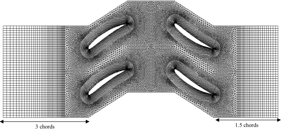
According to Farhanieh et al. [7], only 2 blades were selected for the 2-D numerical study for rotor and stator passages. As the stall cells are assumed to appear near the shroud [10], the numerical procedure is carried out at 80% of the blade span. Each Passage is divided into 4 domains: 2 H-grid for upstream and downstream of the blades, one O-grid around the blades, and one unstructured triangular near the cascade. The total number of mesh cells finally reaches to 69610 cells
(Figure 1). The cells distribution in each section is described in Table 1. The aero-thermodynamic flow characteristics are set as the Table 2.
The upstream boundary of the mesh is located at about 3 chords of the rotor blades. The downstream boundary is extended up to 1.5 chords of the stator blades.
TABLE 1. Nodes distribution
Rotor Stator
O-blade 210×40 210×40
Δ-cascade 12176 12188
H-channel 50×60 40×60
TABLE 2.Aero-thermodynamic characteristics of the cascade
Stagger angle of rotor and stator 30º
Rotor and stator profile NACA65-(A10)
Solidity 1.35
tip hub r
r / 0.7
tip
r 8.5 cm
in
P 100 kPa
in
T 300 Kº
r
U 68 m/s
RPM 955
Figure 1. Mesh generated for 2-blade cascade
Based on the experimental work [20], the injectors are located at a specified distance of the leading edge of the rotor cascade in order to overcome the stall cell creation between the blades. The effects of the air injectors can be roughly characterized by their effects on the compressor map. The experimental results indicated that the compressor map could be altered by air injection.
4. 3. Boundary Conditions All the calculations were run at total pressure of 100 kPa and total temperature of 300 ºk as well as those reported by Murray [12]. Steady boundary conditions were adopted at both inlet and outlet boundaries. The inlet flow is subsonic with a Mach number of 0.17 with a fixed total pressure, fixed total temperature and the zero angle of attack. The stagnation pressure was set as the external boundary which was calculated upon the flow coefficient (f) and pressure coefficient (y) as set for each test. Non-slip and adiabatic conditions were also set all over the solid walls. For all the cases, numerical simulations were started with the unsteady solution. The time step is calculated upon the cascade’s length, tangential speed of the rotor blade, and the total time per revolution.
In this 2-D simulation, the rotor cascade moves at a specific speed relative to the stationary stator passage to simulate the rotating motion. The location where the flow enters into stator cascade from the rotor section is called the interface zone. To evaluate the interface fluxes, the intersection between the interface zones is determined at each time step. The number of faces at the intersection zones varies as the interface zones move relative to each other. Principally, fluxes across the grid interface are computed using the faces of the two interface zones.
All the injections have a fixed static pressure which is set to their maximum pressure of 80 psi at their supply tank. Figure 2 illustrates the locations of injectors for both circumferential and azimuthal direction. The valves are embedded at the casing and connected to their supply tank. The air injectors are on-off type injectors driven by solenoid valves [12]. As the mass flow rate drops during operation, the injectors are switched on continuously. Regarding the significant head losses at the injector faces, between the valves and the pressure source, the injector back pressure does not represent an accurate actual velocity of the injected air on the rotor face. Hence, the maximum velocity of the injected air measured at a distance equivalent to the rotor-injector distance for 50 and 60 psi are approximately 30.2 to 33.8 m/s. The direction of the injection is also determined by velocity components of the flow injected through the rotor passage. This angle may also vary between 27º and 40º according to the test experimental reported works [12].
5. THE CODE VALIDATIONS
The computed compressor characteristic curve was compared with that achieved from experiments from [12], in Figure 3 at the nominal rotation speed. For numerical simulation, different cases were set. According to Table 3, in 5 small intervals, the inlet and the outlet static pressure (P1,P2) were captured and then ψ was calculated and averaged. The head coefficient is at low mass flow rates and the stability condition is found at f=0.316. At higher mass flow rates, the numerical simulation shows a considerable shift off from the actual values due to the higher mass flow rates achieved in experimental measurements [12] and, probably the model of standard k-ε.
Figure 2. Location of the injection valve
Rotor Stator
Injector
Hub Casing
b) Azimuthal direction 10.4 cm
cm
High pressure solenoid valve (connected to a supply tank of 80 psi).
TABLE 3. Pressure coefficient captured from f=0.5
Time Step P1 (Pa) P2 (Pa) y
105 98714 101422 0.273
110 98778 101422 0.266
115 98833 101423 0.261
120 98877 101423 0.256
125 98914 101423 0.253
Figure 3. Head coefficient with respect to the flow coefficient
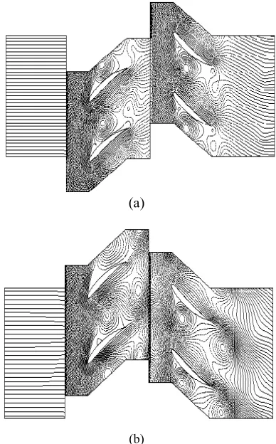
(a)
(b)
Figure 4. Instantaneous flow field without injection, a) Growth of stall cells, b) Blockage initiation
Figure 5. Axial velocity traces at the middle of the interface without injection
6. DISCUSSION OF RESULTS
6. 1. Propagation of the Rotating Stall Figure 4 depicts the computed flow streams during the rotating stall phenomenon of the compressor. The flow coefficent is set to 0.4 and the corresponding head coefficient is set to 0.35 to provide the unstable condition. Figure 4-a illustrates the stall cells initiation almost in the rotor cascade. After the next revolution, the cells grow in size, move through the stator cascade, spread over and diffuse within the passage with a blockage initiation (Figure 4-b). The existance of rotating stall induced vortices that fortify the expectations of significant energy losses and consequently, the performance reductions. The axial velocity traces in absence of injection in period of 20 revolutions of rotor at y =0.35 is also shown in Figure 5. Significant fluctuations of velocity are completely depicted and the pressure rise of the stage drops from 1.0350 (nominal operation) to 1.0235. The first spikes are appeared within the rotor cascade after one compressor rotation and velocity signals indicate almost 10 revolutions before the flow exhibits a rotating stall. It takes 3 revolutions to initiate from a high amplitude part-span stall into a fully developed rotating stall. The simulation shows a stable full-span stall phenomenon with a lower amplitude and mean axial velocity of 24.2 m/s. It is also noticeable from Figures 4 and 5 that the configuration and time history of the stall cells causes the velocity fluctuations vary. When the cell eyes grow in size, the mass flow rate slows down drastically. The unsteady nature of the Rotating Stall (RS) causes chaotic flow patterns which means the mass flow fluctuates during the RS.
6. 2. Effects of Air Injection on Flow Instability The effect of air injection on the system can be demonstrated by modifying various degrees of the
injection setups. For the current study, the back pressure of the injector is 60 psi, and the injector angle is 27º relative to the axial flow. According to the experimental work [12], each injector can add approximately 1.7% continous mass to the system at 60 psi. Hence, the steady operation of compressor is set upon total 3.4% difference between inlet and outlet mass flow rates. Figure 6 presents the axial velocity traces at the interface after injection and the enlarged view of the injection jet for Ψ=0.35 at its steady performance.
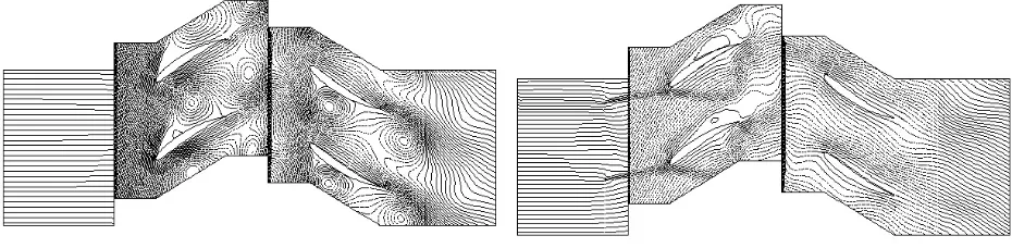
As it is observed, the effect of injection is completely sensible to the flow characteristics. The flow is considerably smoothed and consequently, velocity fluctuations are reduced. A comparison between the streamlines of injected and not injected cases, are shown for three different time steps from Figures 7 to 9. The injection impacts the stall cells and causes them to be removed, which re-stabilizes the flow (Figure 9-b). However, some minor vortices which are captured after the injection shows the sensitivity of injection rates and their locations (Figure 7-b).
(a) Stabilized axial velocity traces at the middle of the interface after
injection (b) Enlarged view of axial velocity
Figure 6. Axial velocity traces at the middle of the interface without injection
(a) Without injection (Unstable pattern) (b) With injection (Stabilized pattern)
Figure 7. Flow pattern of unstable and stabilized conditions at time step 1
(a) Without injection (Unstable pattern) (b) With injection (Stabilized pattern)
(a) Without injection (Unstable pattern) (b) With injection (Stabilized pattern)
Figure 9. Flow pattern of unstable and stabilized conditions at time step 3
Figure 10. Pressure rise with and without injection Figure 11. Comparison of compressor characteristics with and without injection
Figure 10 also shows the effect of different air injection on the pressure rise for Ψ = 0.35. After a short transient response, the flow interacts with the high pressure fluid entering the system and the immediate effect of injection is clearly captured. The injection back pressure of 60 psi gives a smooth operation. Besides, the 17.42% increase in pressure rise up to 1.055 which happens after approximately 6 revolutions. This fortifies the expectation of performing higher injection pressures which may cause more effective flow re-stabilization rather than lower ones.
A comparison of compressor operation was also carried out for both stable and unstable conditions (Figure 11). The results demonstrate good agreements with experimental data. The compressor characteristic curve is shifted up in the presence of continuous air injection and it is more affected on the left of the pressure peak. The maximum effect of air injection belongs with low mass flow rates by approximately 15% to 47% increase in head coefficient. Even it is predictable to have significant effects by the injection
technique, but it is more noticeable to see how a 2D approach can evaluate the quantities of the main parameters.
7. CONCLUSIONS
A multi-block 2-D finite-volume solver was developed to investigate the behavior of the rotating stall phenomena in a single-stage low-speed axial compressor. The air injection technique was also employed to damp the flow instability and remove the stall cells. The following remarks summarize this study: v An experimental high cost observation of rotating stall in axial compressors is numerically simulated during a simplification of the geometry in a manner of cascade length reduction and 2-D simulation, to minimize the CPU time and overall study costs. v The numerical simulation is compared with
Numerical responses show a high accuracy for simulation in low mass flow rates around the peak pressure and the stability point is also well predicted.
v The method of air injection through the compressor cascade was set to investigate the effect of injecting technique on the flow instability. The results show the smoothing effect of inlet injection technique on stall fluctuations and the performance recoveries. v The pressure rise of the compressor increases from
1.032 (nominal operation) to 1.055 (17.42% increase) which is an effective change for one stage of an axial compressor. It is also noticed that in low mass flow rates, the flow is more sensible to injection rather than high ones which indicating that in lower mass flow rates the difference between momentum of air injecting into the system and the main flow is quite large. Hence, the injecting has more effects (Figure 11). The flow visualizations in Figures 7 to 9, not only gave a clear pattern during the stall propagation, but also provided a step by step depiction of the injection effects on flow pattern and consequently the re-stabilizing procedure.
v
As the final result, one may find out that actually, with a reduced simple 2-D model, the complicated study of the flow re-stabilizing are performed quite desirable for the future similar investigation.8. REFERENCES
1. Day, I., Breuer, T., Escuret, J., Cherrett, M. and Wilson, A., "Stall inception and the prospects for active control in four high-speed compressors", Journal of Turbomachinery, Vol. 121, No. 1, (1999), 18-27.
2. Inoue, M., Kuroumaru, M., Tanino, T., Yoshida, S. and Furukawa, M., "Comparative studies on short and long length-scale stall cell propagating in an axial compressor rotor",
Journal of Turbomachinery, Vol. 123, No. 1, (2001), 24-32.
3. Jahnen, W., Peters, T. and Fottner, L., An experimental flow investigation if an hp five-stage compressor exhibiting rotating stall due to distorted inlet flow conditions, in Unsteady aerodynamics and aeroelasticity of turbomachines, Springer, (1998), 243-257.
4. Hah, C., Schulze, R., Wagner, S. and Hennecke, D., "Numerical and experimental study for short wavelength stall inception in a low-speed axial compressor", Proc. of the 14 th ISABE, (1999), 99-7033.
5. Saxer-Felici, H., Saxer, A., Inderbitzin, A. and Gyarmathy, G., "Prediction and measurement of rotating stall cells in an axial compressor", Journal of Turbomachinery, Vol. 121, No. 2, (1999), 365-375.
6. Nishizawa, T. and Takata, H., "Numerical study on stall flutter of a compressor cascade:(1st report, numerical method and numerical example)", JSME International Journal. Series B,
Fluids And Thermal Engineering, Vol. 43, No. 3, (2000),
351-360.
7. Farhanieh, B., Amanifard, N. and Ghorbanian, K., "A 2-D numerical investigation on the modal characteristics of rotating-stall with a variable-cascade-length approach in an axial compressor", International Journal of Engineering
Transaction B: Applications, Vol. 16, No. 1, (2003), 81-90.
8. Ghorbanian, K. and Amanifard, N., "A numerical investigation on the unstable flow in a single stage of an axial compressor",
International Journal of Engineering-Transactions A: Basics,
Vol. 16, No. 2, (2003), 171.
9. N., A., "Stall vortex shedding over a compressor cascade",
International Journal of Engineering Transaction B:
Applications, Vol. 16, No. 1, (2005), 9-16.
10. Gourdain, N., Burguburu, S., Leboeuf, F. and Miton, H., "Numerical simulation of rotating stall in a subsonic compressor", Aerospace Science and Technology, Vol. 10, No. 1, (2006), 9-18.
11. Xue-lei, Z., Song-ling, W., Hai-ping, C. and Lan-xin, Z., "The influence of igv and relative humidity of air on performance map of axial flow compressor", in TENCON 2005, IEEE Region 10, IEEE.,(2005), 1-3.
12. Yeung, S., Wang, Y. and Murray, R. M., "Evaluation of bleed valve rate requirements in nonlinear control of rotating stall on axial flow compressors", (1998).
13. Amanifard, N., Nariman-Zadeh, N., Farahani, M. and Khalkhali, A., "Modelling of multiple short-length-scale stall cells in an axial compressor using evolved gmdh neural networks", Energy
Conversion and Management, Vol. 49, No. 10, (2008),
2588-2594.
14. Chen, P. and Qin, H., "Bifurcation control of rotating stall in axial flow compressors via dynamic output feedback", in Intelligent Control and Automation (WCICA), 2010 8th World Congress on, IEEE, (2010), 2919-2924.
15. Javadi Moghaddam, J., Farahani, M. and Amanifard, N., "A neural network-based sliding-mode control for rotating stall and surge in axial compressors", Applied Soft Computing, Vol. 11, No. 1, (2011), 1036-1043.
16. Hoffmann, K. A., "Computational fluid dynamics for engineers(book)", Austin, TX: Engineering Education System,
(1989).
17. Peyret, R., "Handbook of computational fluid mechanics", Academic Pr, (1996).
Numerical Observation of Flow Re-stabilizing via Air Injection during the Rotating
Stall through a Single-stage Axial Compressor by a 2-D Finite-Volume Approach
P. Mojtabavi, N. Amanifard, H. M. Deylami
Department of Mechanical Engineering, Faculty of Engineering, University of Guilan, P.O. Box 3756, Rasht, Iran
P A P E R I N F O
Paper history: Received 01 July 2012
Received in revised form 15 January 2013 Accepted 28 February 2013
Keywords:
Axial Compressor Numerical Approach 2-D, Stabilizing Air Injection.
هﺪﯿﮑﭼ
ﯽﺳرﺮﺑدرﻮﻣيدﺪﻋترﻮﺼﺑيرﻮﺤﻣرﻮﺳﺮﭙﻤﮐﮏﯾيﺎﻫﻪﺼﺨﺸﻣوﯽﮑﯿﻣﺎﻨﯾدوﺮﯾآرﺎﺘﻓرﺮﺑيدوروياﻮﻫﻖﯾرﺰﺗتاﺮﯿﺛﺎﺗ ﺖﺳاﻪﺘﻓﺮﮔراﺮﻗ
.
يدﺪﻋترﻮﺼﺑاﻮﻫﻖﯾرﺰﺗنوﺪﺑﺺﺨﺸﻣﯽﻫﺎﮕﺸﯾﺎﻣزآرﻮﺳﺮﭙﻤﮐﮏﯾدﺮﮐرﺎﮐﻪﯿﺣﺎﻧرددﺮﮑﻠﻤﻋﯽﻨﺤﻨﻣ
ﺪﺷﻪﺘﻓﺮﮔ
.
ﺑرﺎﺒﺘﻋاياﺮﺑ رﺎﺷيزﺎﺳاﺪﺟﻢﺘﯾرﻮﮕﻟاسﺎﺳاﺮﺑﻪﮐﺖﺧاﻮﻨﮑﯾﺮﯿﻏيﺪﻌﺑوددوﺪﺤﻣﻢﺠﺣﺮﮕﻠﯿﻠﺤﺗﻪﺑنﺪﯿﺸﺨ
نو
-يﺎﻫهﺪﻨﻨﮐدوﺪﺤﻣﻪﺑطﻮﺑﺮﻣﻪﮐﺮﯿﻟ
TVD
ﺖﻧﻻﻮﺑرﻮﺗلﺪﻣو
K-ε
ﻖﺑﺎﻄﺗهﺪﺷﻪﺒﺳﺎﺤﻣﺞﯾﺎﺘﻧ،ﺖﺳاهﺪﺷهدﺎﻬﻧﺎﻨﺑ
ﺎﮕﺸﯾﺎﻣزآﺞﯾﺎﺘﻧﺎﺑﯽﺑﻮﺧ ﺪﻫدﯽﻣنﺎﺸﻧارﯽﻫ
.
ﺪﻌﺑﻪﻠﺣﺮﻣرد دﻮﺒﻬﺑندادنﺎﺸﻧياﺮﺑ،
طﺎﻘﻧاﻮﻫﻖﯾرﺰﺗﻦﯿﺣرددﺮﮑﻠﻤﻋﯽﻨﺤﻨﻣ
ﺶﻫﺎﮐﻪﺠﯿﺘﻧردوهﺪﺷهدادﺮﯿﯿﻐﺗﯽﮑﯿﻣﺎﻨﯾدوﺮﯾآراﺪﯾﺎﭘﺎﻧنﺎﯾﺮﺟطﻮﻄﺧوراﺪﯾﺎﭘﺎﻧﺮﯾدﺎﻘﻣﻪﺑدﺮﮑﻠﻤﻋ ﯽﺳﻮﺴﺤﻣﯽﯾآرﺎﮐ
دﻮﺷﯽﻣﺺﺨﺸﻣ
.
ﺲﭙﺳ ، اﻮﻫﻖﯾرﺰﺗﮏﯿﻨﮑﺗيدﺪﻋﻪﯿﺟﻮﺗياﺮﺑ ﻢﻫاﺮﻓيدﺪﻋترﻮﺼﺑيدوروزﺎﯿﻧدرﻮﻣ ياﻮﻫﻖﯾرﺰﺗ،
ﺎﻬﻠﮑﺷﯽﻣﺎﻤﺗوﺪﯾدﺮﮔ ﺪﯾدﺮﮔفﺮﻃﺮﺑﯽﯾآرﺎﮐﺺﺨﺸﻣدﻮﺒﻬﺑﻂﺳﻮﺗنﺎﯾﺮﺟراﺪﯾﺎﭘﺎﻧي
.