OPTIMIZATION OF SINGLE STAGE AXIAL FLOW
COMPRESSOR FOR DIFFERENT ROTATIONAL
SPEED USING CFD
Anand Kumar S malipatil
1,
Anantharaja M.H
21,2
Department of Thermal Power Engineering, VTU-RO Gulbarga , (India)
ABSTRACT
The model represents a single stage axial compressor comprised of two blade rows. The first row is rotor with
16 blades; the second is row is stator with 32 blades. Here our aim is to find the speed (RPM) of the rotor such
that the pressure at the exit should be higher, as the compressor fluid with high of value pressure. Different rpm
were selected for analysis like 30000,34000,35000,36000,37000,37500,38000 and 39000 through CFD analysis
using commercial code ANSYS FLUENT is used to analyze the transient flow in an axial compressor stage..
Standard k-ε turbulence model with standard wall function is used for analysis. From this we can find that rotor
with 37500rpm is giving better results with highest pressure at the stator outlet.
Keywords: Axial Compressor, Computational Fluid Dynamics, Rotational Speed, Pressure Rise,
K-
Ε Model.
I INTRODUCTION
Compressor is a machine designed to deliver gas at a pressure higher than that originally existing. Pressure rise,
working pressure, specific speed and mechanical design form the basis of differentiation and classification.
Initially, these machines can be divided into positive displacement and dynamic categories. The methods
employed to achieve compression are: Trap consecutive quantities of gas in some type of enclosure, reduce the
volume, thus increasing the pressure and then push the compressed gas out of the enclosure. Trap consecutive
quantities of gas in some type of enclosure; carry it without volume change to the discharge opening pressing
the gas by overcoming back flow from the discharge system and pushing the compressed gas out of the
enclosure. Compress the gas by the mechanical action of rotating impellers or bladed rotors that impart velocity
and pressure to the flowing gas. Additional velocity energy in the gas is converted to pressure in an adjacent
stationary diffuser or blade. Entrained gas in a high velocity jet of another compatible gas convert the high
velocity of the mixture into pressure via a diffuser.
Axial compressors are dynamic machines in which the gas flow is accelerated in an axial and peripheral
direction by the rotation of specially shaped blades. The process flow is parallel to shaft centerline. Stator blades
allow the recovery of velocity to pressure. M Javed hyder and M Omair khan (2007)[1], presented a novel
method for selection of blade material for axial flow compressors. The method is based on the centrifugal
stresses developed at the root of the blade in the first stage of the compressor. Blade tip speed, rotational speed,
blade height and blade material were found to be the most important parameters that determine the magnitude of
stresses developed inside the blades. Niclas Falck (2008)[2], developed a method for analyzing the axial flow
compressor based on the mean line design principles. Mass flow rate, pressure ratios, various loss coefficients,
stage loading factors, rotational speeds etc. were considered for the analysis of compressor cascades. Results
were determined using programs developed in MAT LAB. Hanoca P and Shobhavathy M T (2011)[3] are
conducted the axial spacing between the rotor and stator is an important parameter and has a strong influence on
the performance of axial turbo machines. A study has been carried out to verify the effect of axial spacing on the
performance of 1.35pressure ratio single stage transonic compressor stage through CFD analysis using
commercial code ANSYS FLUENT. Standard k-ε turbulence model with standard wall function was used for
analysis by Kumbhar Anil H. Aashish Agarwal in (2013) . The purpose of the work is to investigate the flow
pattern of single stage axial compressor and hence, optimize the single stage axial compressor for better flow
process.CFD analysis is carried out on the available design of the of single stage axial compressor and it is
found that the flow in the of single stage axial compressor is non-uniform
.
The flow in single stage axialcompressor comprises of two blades, the first row is the rotor with 16 blades, the second row is the stator with
32 blades. The objective of this paper is to find the speed of the rotor such a way that the pressure at the exit
should be higher as the compressor should give the fluid with high value of pressure, different RPM where
selected for the analysis.
II METHODOLOGY
Axial flow compressor blades are generated by using the CATIA V5 R20 modelling software as shown in the
figure. Then the CFD simulations for the available axial flow compressor are carried out and the results of
velocity streamlines and pressure at outlet are plotted. and analysis is done using ANSYS solver, the simulations
are carried out for axial flow compressor blades with different RPM.
2.1 Analysis
CFD Analysis and study of results are carried out in 3 steps: Pre-processing, Solving and Post-processing.
2.2 Pre-Processing
Geometry of the CAD model is prepared in CATIA V5 R20 modeling software, and imported into the ANSYS
Workbench by using the STEP format. Meshing is carried out using the ANSYS MESHER TOOL by defining
the element size for the fluid domain and giving finer surface mesh on the regions of interest like inlet, outlet
and wall.
2.3 Solving
The solver chosen in this project is ANSYS solver, which is a finite volume based solver. The mesh generated
defining the problem set up i.e. defining the boundary conditions, defining viscosity, type of gas, mass flow rate,
initial temperature, initial pressure etc. and the solution is carried out by assigning number of iterations.
2.4 Post-Processing
Extracted physical quantities from the solver are visualized. Extracted physical quantities like velocities and
pressures are displayed in various ways. ANSYS post processing was used for post processing the results.
2.5 Geometry Creation
CATIA as discussed in 1st chapter is an interactive application software used to generate 3 dimensional models
with the help of computer, here in this project we are using mechanical surface design and sketcher feature to
create axial flow compressor blades model as per the 3D details as shown in Figure 2 created in CATIA.
Geometry Parameters
Inlet radius = 127mm
Outlet radius = 216 mm
Length of the blade = 90 mm
Rotor angle between each blades = 22.50
Stator angle = 11.250
2.6 Meshing
In the 2nd phase of the project meshing and CFD analysis for the base case and the different cases considered for
optimization is performed. ANSYS Workbench, which consists of ANSYS Meshing Tool, ANSYS Solver and
ANSYS post processor is the software used for this assessment. CFD simulation is performed for all the cases
and the results are presented and compared by using the ANSYS Post Processor. The mesh model generated by
using ANSYS Mesh Tool is shown in Figure 3.
Fig 2: Geometry Creation in Catia V5R20 Fig3: Meshing of the geometry
2.7 Grid Independence Study
A grid independence study on unstructured meshes for the axial flow compressor was carried. The meshing was
simulations for the axial flow compressor with different mesh numbers, comparing the results and getting a grid
independent mesh size. It was found that the solution no longer changes for a size of the mesh element of 3 mm
which gives a total number of elements as 20,000 and therefore this was kept constant for simulations.
III BOUNDARY CONDITIONS.
The boundary conditions specified in this project are:
Mesh Model
Solver type: Pressure based
Problem model: Standard k- ε
Material
Fluid: Air
Boundary condition
Inlet condition: 1atm Total gauge pressure.
Outlet condition: 1.08 atm.
Wall condition: stationary and no slip condition
IV RESULTS AND DISCUSSION
Analysis results of Optimized designs are shown in this section, and comparison of the results of the different
RPM for optimization is presented.
Total Pressure distribution at the inlet and outlet
Fig 4
.1 for
30000RPM Fig 4.2
for
34000RPM
Fig 4.5
for
37000RP Fig 4.6
for
37500RPM
Fig 4.7
for
38000RPM Fig 4.8
for
39000RPM
From the above pressure contour diagrams the color indicates the pressure variation from rotor inlet to the stator
outlet. As the fluid enters the rotor of the compressor with high velocity, the velocity goes on decreasing and
pressure goes on increasing because the stators which are in between the each rotor blade causes the flow to be
diffused.
From the fig 4.1, as the fluid enters the rotor at inlet condition of 1atm total gauge pressure at 30000 RPM it
gives the outlet pressure of 109653pascal. As we increase the rotational speed say 34000RPM the outlet
pressure will go to109819pascal.
Similarly as there is increase in the rotational speed like 35000RPM, 36000RPM, 37000RPM and 37500RPM
the outlet pressure will go to 109871pascal, 109904pascal, 109953pascal and110396pascal respectively. Further
increase in the rotational speed will never exceeds the maximum outlet pressure i,e 110396pascal this is because
of limitation of the compressor.
For a rotational speed of 38000RPM and 39000RPM the outlet pressure rise is 110396pascal and 110297pascal,
the pressure rise is not exceeding the 110396pascal.
4.1 Velocity Streamlines
In the case of velocity streamlines, as the fluid enters the rotor, initially the velocity is high. As it flows inside,
the velocity goes on decreasing because of the occurrence of the flow diffusion. The velocity goes on decreasing
up to 37000RPM and for 37500RPM the velocity suddenly increases, then it decreases. The velocity streamlines
Figure 4.9: Velocity Streamline for 30000 RPM Figure 4.10: Velocity Streamline for 34000 RPM
Figure 4.11: Velocity Streamline for 35000 RPM Figure 4.12: Velocity Streamline for 36000 RPM
Figure 4.13: Velocity Streamline for 37000 RPM Figure 4.14: Velocity Streamline for 37500 RPM
4.2 Graphs and Table
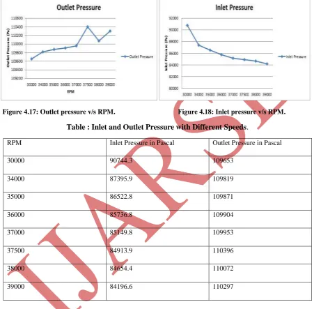
The above graph shows the variation of outlet pressure for various rotational speeds. In this graph the pressure
rise at the beginning is low because of higher velocity, as the speed increases the pressure rise goes on
increasing up to the speed of 37500 RPM. At this speed the pressure drop reaches the peak value then decreases.
Figure 4.17: Outlet pressure v/s RPM. Figure 4.18: Inlet pressure v/s RPM.
Table : Inlet and Outlet Pressure with Different Speeds
.
RPM Inlet Pressure in Pascal Outlet Pressure in Pascal
30000 90744.3 109653
34000 87395.9 109819
35000 86522.8 109871
36000 85736.8 109904
37000 85149.8 109953
37500 84913.9 110396
38000 84654.4 110072
39000 84196.6 110297
The above Table shows Inlet and Outlet Pressure with Different Speeds of the the axial flow compressor,
initially the inlet pressure at the rotor entrance is low like 90744.3 pa, 87395.9 pa, 86522.8 pa, 85736.8 pa,
85149.8 pa, 84913.9 pa, 84654.4 pa and 84196.6 pa as it flows through the axial compressor the pressure
increases at the rotor outlet as 109653 pa, 109819 pa, 109871 pa, 109904 pa, 109953 pa, 110396 pa, 110072 pa
and 110297 pa respectively, with increasing speed of the axial flow compressor from 30000 to 39000 rpm the
stator blades which are in between each rotor blade cause the flow to be diffused. This is because of increasing
V CONCLUSIONS
A steady state CFD analysis has been carried out to optimize the axial flow compressor for different rotational
speed using CFD technique. Eight different speeds for axial flow compressor were compared with their outlet
pressure rise and presented through graph contours.
In the investigation it was observed that the stator outlet pressure for 37500 RPM gives higher pressure
rise. As the speed increases the pressure increases up to the 37500 RPM , thereafter increasing the
speed, decreases the pressure due to limitation of the compressor.
In case of velocity stream line, the velocity goes on decreasing with increase in the speed, up to 37500
RPM. After that the velocity increases and then suddenly decreases after 37500 rpm.
As per criterion for selection of better speed for axial flow compressor, the stator should have higher
pressure rise with low velocity. The speed of 37500 have higher pressure rise with low velocity.
Compared to all speeds of the Compressor, 375000 rpm gives the maximum stator outlet pressure rise
having the value 110072 Pascal. So it is clear that 37500 RPM is the optimal speed for this model.
REFERENCES
[1]. .M Javed hyder and M.Omair Khan,” Development of Novel method for the selection of Material for Axial
compressor blade”, Conference on failure of Engineering materials and structures, MEDUET TAXILA,
Feb 2007, pp: 73-78.
[2]. Niclas Falck, “Axial compressor mean line design”, masters thesis, Lund University, Sweden, Feb 2008.
[3]. Hanoca P and Shobhavathy M T “CFD analysis to investigate the effect of axial spacing in a single stage
transonic axial flow compressor” Symposium on Applied Aerodynamics and Design of Aerospace Vehicle
(SAROD 2011) November 16-18, 2011, Bangalore, India.
[4]. MC Kenzie AB, “The design of axial compressor blading based on tests of a low speed compressor”,
proceedings of IMech (E), Vol 194, issue 6, 1980, pp: 103-111.
[5] H Cohen , GFC Rogers & HIH Sarvanamato, “Gas turbine theory “,Pearson education limited ,fifth edition,