A CONTINUOUS PLANE MODEL TO MACHINE LAYOUT
PROBLEMS CONSIDERING PICK-UP AND DROP-OFF POINTS:
AN EVOLUTIONARY ALGORITHM
R. Tavakkoli-Moghaddam
Department of Industrial Engineering, Faculty of Engineering University of Tehran, Tehran, Iran, [email protected]
(Received: December 12, 2001 – Accepted in Revised Form: February 6, 2003)
Abstract One of the well-known evolutionary algorithms inspired by biological evolution is genetic algorithm (GA) that is employed as a robust and global optimization tool to search for the best or near-optimal solution with the search space. In this paper, this algorithm is used to solve unequal-sized machines (or intra-cell) layout problems considering pick-up and drop-off (input/output) points. Such problems may be formulated as a continuous plane model that is applicable to cellular manufacturing systems. The aim is to assign all the machines to the related locations within the floor plan in such a way that an objective function, as the total material handling is optimized while satisfying all the constraints. In this paper, a GA methodology is used to generate promising and feasible layout solutions and to find the best or near-optimal solution searched within the space problem. For this purpose, a new genetic presentation and genetic operators are designed. Finally, computational results reported by the GA program and a construction algorithm are presented in the context of the test problems. In addition to the above objective function, the dead space ratio of final layout solution is calculated for each test problem.
Key Words Machine/Cell Layout Problems, Mathematical Programming Models, Pick-Up/Drop-Off Points, Evolutionary Algorithms
ﻩﺪﻴـﻜﭼ
ﻩﺪﻴـﻜﭼ
ﻩﺪﻴـﻜﭼ
ﻩﺪﻴـﻜﭼ
ﻲﻣ ﻲﺘﺴﻳﺯ ﻞﻣﺎﻜﺗ ﻱﺮﻴﮔﺭﺎﻜﺑ ﺎﺑ ﻪﻛ ﺖﺳﺍ ﻲﻳﺎﻫ ﻢﺘﻳﺭﻮﮕﻟﺍ ﻦﻳﺮﺘﻬﺑ ﺯﺍ ﻲـﻜﻳ ﻚﻴـﺘﻧﮊ ﻢﺘـﻳﺭﻮﮕﻟﺍ ﻞﻳﺎﺴﻣ ﺪﻧﺍﻮﺗ
ﺪﻨﻛ ﻞﺣ ﺍﺭ ﻱﺯﺎﺳ ﻪﻨـﻴﻬﺑ .
ﻝﻮﻠﺳ ﺎﻳ ﺎﻫ ﻦﻴﺷﺎﻣ ﺭﺍﺮﻘﺘﺳﺍ ﻪﺑ ﻁﻮﺑﺮﻣ ﻞﻳﺎﺴﻣ ﻦﻳﺍ ﺯﺍ ﻲﻜﻳ ﺎﻫ
ﻱﺍﺭﺍﺩ ﻱ ﻭ ﻥﺎﺴﻜﻳ ﺮﻴﻏ ﻩﺯﺍﺪﻧﺍ
ﺖﺷﺍﺩﺮﺑ ﻭ ﺖﺷﺍﺬﮔ ﻁﺎﻘﻧ ﻦﺘﻓﺮﮔ ﺮﻈﻧ ﺭﺩ ﺎـﺑ )
ﻲﺟﻭﺮﺧ ﻭ ﻱﺩﻭﺭﻭ (
ﺪﺷﺎﺑ ﻲﻣ .
ﻪﻟﺎﻘﻣ ﻦﻳﺍ ﺭﺩ ،
ﻚﻳ ﻪﺤﻔﺻ ﻲﺿﺎﻳﺭ ﻝﺪﻣ
ﻲﻟﻮﻠﺳ ﺪﻴﻟﻮﺗ ﻱﺎﻫ ﻢﺘـﺴﻴﺳ ﺭﺩ ﻪـﻛ ﺖـﺳﺍ ﻩﺪـﺷ ﻪـﻳﺍﺭﺍ ﻪﺘـﺳﻮﻴﭘ ﺩﺮﺑﺭﺎﻛ
ﺩﺭﺍﺩ . ﻦﻳﺍ ﻑﺪﻫ ﺍ ﺭﺩ ﺎﻫ ﻦﻴﺷﺎﻣ ﻪﻴﻠﻛ ﻪﻛ ﺖﺳ
ﺰﻫ ﻲﻨﻌﻳ ﻥﺁ ﻑﺪﻫ ﻊﺑﺎﺗ ﻪﻛ ﻱﻮﺤﻧ ﻪﺑ ﺪﻨﺑﺎﻳ ﺭﺍﺮﻘﺘﺳﺍ ﻪﻃﻮﺑﺮﻣ ﻱﺎﻫ ﻥﺎﻜﻣ ﻪﻨﻳ
ﻞﻘﻧﻭ ﻞﻤﺣ ،
ﺩﺩﺮﮔ ﻞﻗﺍﺪﺣ .
ﻦﻳﺍ ﺭﺩ ﻦﻴﻨﭽﻤﻫ
ﻪـﻟﺎﻘﻣ ، ﻞﺣ
ﻚﻴﺘﻧﮊ ﻢﺘﻳﺭﻮﮕﻟﺍ ﺯﺍ ﻩﺩﺎﻔﺘﺳﺍ ﺎﺑ ﺎﻫ ﻦﻴﺷﺎﻣ ﺭﺍﺮﻘﺘﺳﺍ ﺯﺍ ﻲﻔﻠﺘﺨﻣ ﻱﺎﻫ ﻱﺩﺎﻬﻨﺸﻴﭘ
ﻦﻳﺮﺘﻬﺑ ﻭ ﻪﻳﺍﺭﺍ ﻞﺣ
ﺵﺭﺍﺰﮔ
ﺩﻮـﺷ ﻲـﻣ .
ﺩﺩﺮﮔ ﻲﻣ ﻪﻳﺍﺭﺍ ﻚﻴﺘﻧﮊ ﻱﺎﻫﺭﻮﺗﺍﺮﭘﺍ ﻭ ﮓﻨﻳﺪﻛ ﺯﺍ ﻲﺻﺎﺧ ﻲﺣﺍﺮﻃ ﻦﻤﺿ ﺭﺩ .
ﺩﺭﻮﻣ ﻪﻟﺎﺴﻣ ﻦﻳﺪﻨﭼ ﻪﻤﺗﺎﺧ ﺭﺩ
ﻲﻣ ﺭﺍﺮﻗ ﻲـﺑﺎﻳﺯﺭﺍ
ﻲﻣ ﻪﺴﻳﺎﻘﻣ ﻱﺭﺎﺘﺧﺎﺳ ﺵﻭﺭ ﻚﻳ ﺎﺑ ﺎﻬﻧﺁ ﻞﺣﻭ ﺩﺮﻴﮔ ﻮﺷ
ﺩ .
ﺖﺒﺴﻧ ،ﻕﻮﻓ ﻑﺪﻫ ﻊﺑﺎﺗ ﺮﺑ ﻩﻭﻼﻋ ﻱﺎﻀﻓ
ﻩﺩﺮﻣ ﻲﻣ ﻪﺒﺳﺎﺤﻣ ﻲﻳﺎﻬﻧ ﺭﺍﺮﻘﺘﺳﺍ ﻞﺣ ﻱﺍﺮﺑ ﺩﺩﺮﮔ
.
1. INTRODUCTION
Early researchers in facilities layout problems (FLPs) believed that the best approach to find good solutions was through the development of a model as a quadratic assignment problem (QAP) [1]. Its objective is to minimize the material handling costs incurred by the material flow between each of the paired facilities and distance between each of the paired locations. Demand requirements and
process routes for given part types may be used to generate the elements of the flow matrix. These data are required for the QAP model. The distance matrix is constructed according to the pre-determined location configuration of the given FLP. Therefore, there are n equal-sized blocks representing n locations, where each equal-sized facility belongs to one block/location.
traditional optimization) approaches optimally in order to yield an exact solution. The exact solution is obtained in a reasonable computing time where the problem size is small, say 15 facilities, in a reasonable computational time [2]. It should be noted that the QAPLIB [3] reported that the modest size problems, say 20 facilities, is still considered as a computationally non-trivial task.
Because of the above limit, there is a great demand for good heuristics to solve layout problems with the size of greater than 20 facilities. Kusiak and Heragu [4] classified heuristic approaches in the following ways: construction, improvement, hybrid and graph-theoretic methods. There are no well-known deterministic approaches to solve those NP-hard problems optimally [5]. The QAP is a difficult problem belonging to a broader class of combinatorial optimization problems.
If there are changes in the flow data, then a flexible layout is needed which can be modeled as the QAP by defining a time period for each department. It is supposed that the existing layout is considered as a single-period (static) layout that incurs some costs. When a rearrangement of an existing layout occurs, then the problem known as a DLP is to determine a revised layout in different periods of time. Lacksonen and Enscore [6] proposed an algorithm using a modified cutting plane to solve the QAP form of the dynamic layout problem and mixed-integer linear programming to find the block diagram layout with varying department areas.
Kim at, al. [7] proposed an algorithm based on a combination of a mixed-model scheduling, simulated annealing and graph-theoretic methods for assigning workers to machines in single and double-row layout considering the zone constraint (ie., machines assigned to a worker are adjacently located). The model is mathematically formulated for both the slow period and the peak period, minimizing the variation of workloads and maximizing the preference of workers. Kouvelis et al., [8] applied simulated annealing to the QAP with few zoning constraints resulting in a model called a restricted QAP. A number of equal-sized facilities layout solutions have been reported by genetic algorithms [9]. Krause and Nissen [10] compared six-test problems considering positive zoning constraints with different algorithms using
penalty functions and two multi-objective optimization approaches. A mathematical programming model has been applied by Tavakkoli-Moghaddam [11] to generate large-scale unequal-sized facilities layout solutions using genetic algorithms. In this model, the center-to-center rectilinear method has been used to measure the distance between each pair of facilities. The objective was to find the locations of the center coordinates of facilities (decision variables) so that the total flow-distance cost is minimized.
2. MATHEMATICAL PROGRAMMING MODELS
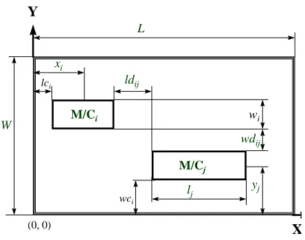
A mathematical programming model is presented to solve unequal-sized facilities layout problems considering the pick-up/drop-off (P/D) points, where the dimensions of the floor plan and each facility can be estimated. However the user may change the floor dimensions to generate alternative layouts. The P/D points are sometimes called input/output (I/O) (or loading/unloading) points. This mathematical model optimizes the objective function subject to constraints, which it finds of the P/D points of all the facilities (as decision variables) to represent a layout solution with respect to the configurations, which apply. Figure 1 helps to follow the notations used in the mathematical model. The reference coordinate is assumed to be the lower-left hand corner of the floor plan. Montreuil and Ratliff [12] proposed an algorithm to find the I/O locations of facilities based on a design skeleton obtained by the cut tree algorithm. Welgama and Gibson [13] presented a construction algorithm to solve the machine layout problem with P/D points, which was used as a test method for the steel industry.
center point has an x coordinate and a y coordinate. The x and y-center coordinates of a machine assigned to the floor plan do not change if the machine rotates. Thus the related orientation of the machine is free if it does not violate any constraint that would apply to the mathematical model.
Instead of the above center coordinates of machines, one point for both pick-up (P) and drop-off (D) or two distinct P/D points are considered for all the machines to be assigned within the floor boundaries. The rectilinear distance between these P/D points determines the loading and unloading movements between each
pair of machines. Welgama and Gibson [13] presented an objective function considering the pick-up and drop-off points. For the simplicity of their model, they assumed that P/D points are located at the midpoint of each machine side parallel with the aisle. However, in the approach of this thesis, any P/D points can be manipulated. They can be anywhere within the perimeter of the rectangular shape of the given machine including its corners. These P/D points have two x and y-coordinates to be determined as decision variables, which contribute to the objective function.
Min.
j n
i n
=
=
∑
∑
1 1cij [ fij ( | xpj - xdi | + | ypj - ydi | ) + fji ( | xpi - xdj | + | ypi - ydj | ) ] (1)
s.t.:
| xpi - xdj | ≥ ½ (li + lj) + ldij ∀i, j (2)
| ypi - ydj | ≥ ½ (wi + wj) + hwij ∀i, j (3)
| xdi - xpj | ≥ ½ (li + lj) + ldij ∀i, j (4)
| ydi - ypj | ≥ ½ (wi + wj) + wdij ∀i, j (5)
| xi - xj | ≤ L - [½ (li + lj) + lci + lcj ] ∀i, j (6)
| yi - yj | ≤ W - [½ (wi + wj) + wci + wcj ] ∀i, j (7)
xi - ½ li≤ xpi≤ xi + ½ li ∀i (8)
yi - ½ wi≤ ypi≤ yi + ½ wi ∀i (9)
xi - ½ li≤ xdi≤ xi + ½ li ∀i (10)
yi - ½ wi≤ ydi≤ yi + ½ wi ∀i (11)
xi , yi , xpi , ypi , xdi , ydi ≥ 0, i = 1, 2, ..., n (12)
where,
n = number of machines
cij = cost per trip per unit distance between machines i and j
fij = material flow from machine i to machine j (forward moves for loading)
fji = material flow from machine j to machine i (backward moves for unloading)
xpi and ypi = x-coordinate and y-coordinate (location) of the pick-up point of machine i
xdi and ydi = x-coordinate and y-coordinate (location) of the drop-off point of machine i
xi and yi = x- and y-center coordinates of machine i respectively.
ldij and wdij = horizontal and vertical clearances between machines i and j respectively
It is assumed that all machines are square or rectangular shapes. If the shape of a machine is irregular, then the machine size is defined as a rectangular block. This block can be considered as one machine so that this machine can be fitted into one block. It is possible to include the clearance between each pair of machines or between a machine and the floor boundaries to the machine, as one block.
It is assumed that the cost per trip per unit distance between machines i and j is considered as unit one (cij = 1) in this thesis. The objective
function (Equation 1) is used to find the location of machines, their configurations (vertical or horizontal positions) and orientation of pick-up and drop-off points so that the total material handling costs are minimized. Appropriate, lci and wci may
be considered in order to give enough space for loading/unloading, maintenance, safety, material handling equipment and work-in-process (WIP) areas between machines and building boundaries while determining relative locations of machines. These clearances can be included in the dimensions of machines and must be satisfied in the constraints.
The first four constraints (Equations 2-5) ensure that there is no overlapping of machines and all machines are fitted within the floor boundaries. It should be noted that the non-overlapping condition is met if only two of the above constraints are satisfied. The next two constraints (Equations 6
and 7) ensure that all machines are located and fitted in the floor plan as well. Constraints in Equations 8-11 guarantee that the P/D points fall within the boundaries of a machine. The last set of constraints guarantee that the variables given in Equation 12 must be real and positive. Two test problems are taken from [13] assigning unequal-sized areas of 6 and 12 machines within the floor plan.
3. GENETIC ALGORITHMS
Genetic algorithms [16 and 17] evaluate a population of strings over a number of generations. There are several key issues that must be considered to enable one to solve any optimization problem using gene tic algorithms. It is first necessary to define an appropriate genetic coding (representation) of a solution (ie., encoding of a phenotype to a genotype); a fitness function measure; genetic operators; the parameters to control the algorithm; and the criteria to terminate the algorithm. An appropriate design of genetic operators affects on the performance of genetic algorithms for facilities layout problems [18]. A general approach can be constructed using the following main steps:
1. Select a good representation (genetic encoding) to encode the search space.
2. Determine an appropriate fitness function and scaling method.
3. Find a selection scheme.
4. Choose and design genetic operators
5. Set the GA parameters to control and terminate the process.
3.1 Structure of Genetic Coding
The standard genetic coding introduced by Holland [18] was in a binary format that is no longer suitable to accommodate facilities in relation to locations or floor plan. Therefore integer numbers are required in designing the genetic coding (genotype) representing a layout solution (phenotype). In the case of unequal-sized facilities layout problem, a chromosome is composed of a sequence of integers representing blocks of eachM/Cj
L
ldij
M/Ci
xi
lj
W
yj
wdij lci
wi
Y
X
wci
(0, 0)
facility. It should be noted that each facility might occupy more than one block.
To solve the above problems using LADEGA, the genetic coding of a layout solution must be designed. LADEGA always generates valid chromosomes by satisfying all the constraints, which forms the chromosome. At the initial stage, all the chromosome bits are set to zero. Figure 2 shows a pseudo code for generating a valid chromosome.
To evaluate the quality of each layout solution,
a transformation of the chromosome (genotype) into the solution (phenotype) is required. The objective value computed must be transferred to the fitness value as LADEGA works on the fitness values.
3.2. Creation of the New Population
A new population is generated from the current (old) population vi a reproduction (duplication), crossover and mutation operators. If the reproduction operator is applied, then an individualGenerate (valid chromosome)
Read the GA parameters and input data.
do
Initialize (or set) all the chromosome bits to zero. Not all the facilities are processed.
Select a facility at random.
Assign the selected facility to the top-left corner of the available floor plan, either horizontally or vertically depending on how dimensions of the facility are stored in the input file.
Deduct the facility area from available space.
Allocate the facility number to the respective locations of the chromosome (this facility is now processed.)
for (1 to N, number of blocks)
if (the chromosome bit is zero) then
Select an unprocessed (new) facility at random.
if (the new selected facility neither exceeds the floor boundaries nor overlaps with another facility, ie. it does not violate the constraints.) then
Assign the new selected facility to the right of the previous facility assigned to the floor plan or to the new row of the floor plan (this facility is now processed.)
else if (the selected facility neither exceeds the floor boundaries nor overlaps with another facility, ie. it does not violate the constraints.) then
Assign the new selected facility to the right of the previous facility assigned to the floor plan or to the new row of the floor plan (it is now processed and rotated.)
else (the selected facility is not processed)
end if
end for
end do (till a valid chromosome is created, ie. all the facilities are assigned and processed)
(called parent) is selected from the current population based on the selection scheme and copied exactly to the new population. If the mutation operator is applied, then a selected individual, according to the selection scheme, is mutated and placed in the new population. In the case of crossover, two individuals are selected and crossed over in order to create two new individuals (called children). The process is repeated when the new population contains N new individuals, where N is the population size.
3.3. Design of Genetic Operators
By using genetic operators new chromosomes are created in the next generation. The mutation operator is applied if the selected random number is equal to or less than the mutation rate defined by the user. In this case, a chromosome (a solution) is first selected according to a selection scheme, say tournament selection, and a facility is selected from the above chromosome. Then LADEGA tries to find another facility with the same dimensions and orientation. If the facility is found, then it is exchanged with the first facility selected. If no facility is found to be exchanged, then the process is repeated for a certain number of iterations, say 100, before it stops.A new mutation operator is developed, in this paper, to change the position of the P/D points of a machine by rotating them 180 degrees relative to the existing machine chosen by the selection scheme. This rotation does not violate the non-overlapping condition. In this case, the locations of the P/D points are changed, not the orientation of the machine. This is always valid for any machine. The following paragraph describes the new GA operator used as a mutation operator. Firstly, a chromosome (parent) is selected based on the selection scheme from the current population. Secondly, an integer number from the interval (1, number of machines (i.e, n)) is randomly selected, which represents a machine to be mutated. Then, LADEGA rotates this machine by 180 degrees horizontally or vertically, depending on its orientation. Thus, the locations of the P/D points of this machine are changed. By doing this, a new layout solution is generated with a different objective value.
To apply a crossover operator, two chromosomes (parents) are first selected according
to the selection scheme. A few facilities are selected at random from the first parent and then they are copied to the same positions of the first new chromosome (offspring). Remaining facilities are obtained from the second parent in order without repeating the previously selected facility numbers. If LADEGA cannot create a new offspring, then a few facilities are selected at random from the first parent and the above process continues. This process is repeated for a certain number of iterations, say 100.
Two chromosomes (parents) are selected according to the selection method from the existing population. Then two crossing points are randomly chosen, between 1 and the number of machines, from the first parent. The machines between these points are copied into the new chromosome and LADEGA tries to orderly (sequentially) assign the remaining machines from the second parent, without any repeating machine number. If a valid chromosome has not been generated after a certain number of iterations (say 50), new crossing points are chosen from the first parent and the above process is repeated. Again, if no valid chromosome is obtained after a certain number of iterations (say 100), the selected chromosome (first parent) is exactly copied to the new population.
4. COMPUTATIONAL RESULTS
require 325 and 1469 standard blocks. This result shows that the sizes of some machines are very large.
A mathematical programming model, discussed in Section 2, is used to solve Wel-6 and Wel-12. Constraints incorporated in the above model may require the following input data: dimensions of machines, material flow between each pair of machines, location restrictions (fixed pre-location), dimensions of the floor plan, orientation of machines, clearance between machines, clearance between machine and floor boundaries, pick-up and drop-off (input/output) points of machines. Further constraints such as aisle structures; door locations; closeness rating known as a qualitative factor; time period involved in dynamic layout problems; and shortest path of material flow can be considered as further research projects.
The Model is the highly constrained formulation in which LADEGA handles the constraints by generating valid chromosomes, on which all constraints are met. The result of a valid chromosome is a feasible layout solution, ie. all the facilities (machines) are assigned in the floor plan.
4.1. Orientation and P/D Points of Machines
Machines can be positioned either parallel to a building structure or at right angles to that position or horizontally/vertically in a graphical sense,depending on the input data given for the dimensions of the machines. The first integer number read in the above input data is considered as the length of the facility and the second number as its width. Using this convention the length of a facility may be less than its width. A facility may rotate if a facility cannot be placed within the floor area. There are six different positions of P/D points for a machine [13].
4.2. The LADEGA Procedure Used for
Wel-6 and Wel-12
There are usually two main components of most genetic algorithms that are problem dependent: the genetic coding and the fitness function. In order to design the former component, decision variables of a layout solution (phenotype) must be encoded into a chromosome, which is a sequence of integers representing facilities numbers to the related locations. The total integer numbers of a chromosome are equal to the total number of blocks, depending on the floor dimensions. As an example, the chromosome length will be 1500 (= 60 × 25) if the floor dimensions are W = 60 by L = 25 for the Wel-12. This length implies that the computational time of LADEGA increases. It should be noted that the complexity of the above problem is equivalent to a layout problem of 1500 equal-sized facilities.In LADEGA, however, a machine may be rotated (ie. its orientation is changed) if it cannot be placed in its position or if it violates one of the constraints discussed in Section 2.2. The initial placement of a machine strongly depends on reading its dimension from the input data. It is not necessary to place a machine with longer sides horizontally. After assigning all the machines (i.e., creating a valid chromosome), LADEGA measures the rectilinear distances between P/D points of machines in order to evaluate the quality of the layout solution.
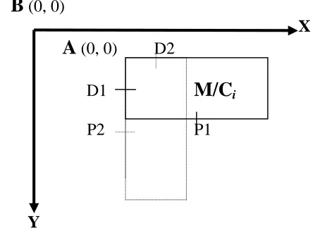
It should be noted that the fixed P/D points of machines, given in the input data, are based on the reference coordinates, relative to the bottom-left corner of each facility. However, LADEGA adjusts the coordinates of P/D points where the reference coordinates are at the top-left corner of the machines. Figure 3 shows the above reference coordinates “A”. A machine can rotate 90 degree around the point “A” if it overlaps with another
B
(0, 0)
X
A
(0, 0) D2
D1
M/C
iP2
P1
Y
TABLE 1. Comparison of Computational Results for the Wel-6 and Wel-12, Showing their Increased Performance in the Parenthesis, in Terms of Times.
Problem Objective value Dead space ratio Perfor-
Constructiona LADEGA Constructiona LADEGA manceb
Wel-6 421.5 565.5 (0.745) 0.370 0.097 (3.814) 197.26 % Wel-12 7193.0 6655.5 (1.081) 0.100 0.021 (4.762) 255.34 %
a) Construction algorithm proposed by Welgama and Gibson [15].
b) Overall performance (%) of LADEGA in respect to the construction algorithm.
5 p d
p d
2 d 6 3 p p
p d
1 p d 4 d
No. 1 2 3 4 5 6
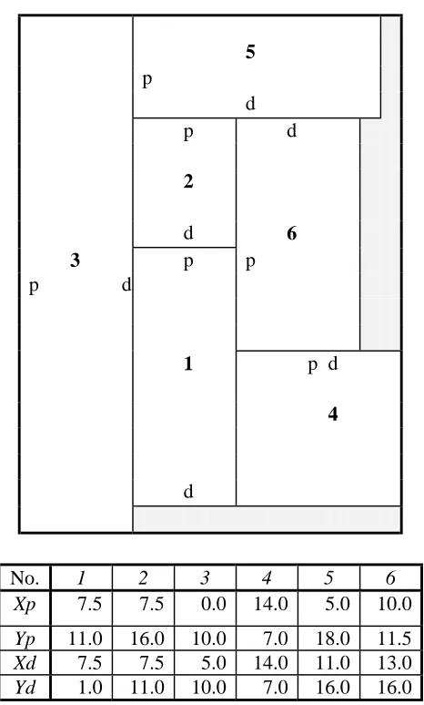
Xp 7.5 7.5 0.0 14.0 5.0 10.0 Yp 11.0 16.0 10.0 7.0 18.0 11.5 Xd 7.5 7.5 5.0 14.0 11.0 13.0 Yd 1.0 11.0 10.0 7.0 16.0 16.0 Width =20, Length = 18,DSR = 0.097
(xp, yp) and (xd, yd) = x and y-coordinates of pick-up and drop-off points respectively
1 0
6 5
p d d p d
p p
d 3
p
8 2
d p
1
p
4 d p 1 1
d
p 1 2 d
9
d
7
p
d
No. 1 2 3 4 5 6 7 8 9 10 11 12
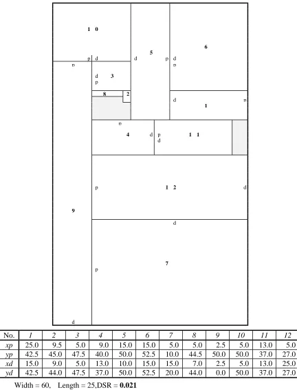
xp 25.0 9.5 5.0 9.0 15.0 15.0 5.0 5.0 2.5 5.0 13.0 5.0 yp 42.5 45.0 47.5 40.0 50.0 52.5 10.0 44.5 50.0 50.0 37.0 27.0 xd 15.0 9.0 5.0 13.0 10.0 15.0 15.0 7.0 2.5 5.0 13.0 25.0 yd 42.5 44.0 47.5 37.0 50.0 52.5 20.0 44.0 0.0 50.0 37.0 27.0
Width = 60, Length = 25, DSR = 0.021
(xp, yp) and (xd, yd) = x and y-coordinates of pick-up and drop-off points respectively.
facility. The reason is that LADEGA considers the point “B” as the reference coordinates of the floor plan and starts assigning a facility from this point to the right of the floor plan. If a machine rotates, then the new P/D points will be as P2 and D2 respectively.
To generate a valid chromosome, first a machine is randomly selected and assigned to the top-left corner of the floor plan. The assignment depends on the given dimensions of the machine defined as length (x) and width (y) respectively. Then, another machine is randomly selected and assigned to the right side of the machine assigned before. Thus, these two machines are adjacent to each other. A machine can be rotated if it overlaps with another machine either in the x direction or in the y direction, or if it exceeds the boundaries of the floor plan. Another machine is selected if the above two conditions are not satisfied
.
4.2. Layout Solutions for Wel-6 and Wel-12
The 6-machines problem (Wel-6) has been taken from [13] with the fixed P/D points. This problem is solved by LADEGA. Nine different floor dimensions experimented give different layout solutions obtained in each case. However, the LADEGA program never converges if the floor dimensions of 17 by 20 are chosen. Because in the above problem, there are 325 equal-sized blocks (areas) in order to allocate all 6 machines.The quality of the layout solution improves when a large population size, ie. 1000, is used in LADEGA. In this case, the best objective value of 565.5 is found at generation 35 out of 50 with the DSR of 0.097. The associated layout solution and its P/D points are shown in Figure 4. The computational results are compared with the results reported by [13], as given in Table 1.
Welgama and Gibson [13] presented a machine layout solution of 7193 with the dead space ratio (DSR) of 0.1 for the Wel-12 using a construction algorithm. They pointed out that the weight for considering the dead space is 40%, which is incorporated in a bi-criteria objective function. It was not
possible to generate a layout solution with the DSR less than 0.1 using their algorithm. However, a better layout solution with the objective value of 6655.5 and a DSR of 0.021 (W = 60 and L = 25) ha been found so far in this study, as shown in Figure 5. This solution indicates an increase in the solution quality by 7.5% (1.08 times better performance) while the space utilization is also improved by 79% (4.762 times better performance).
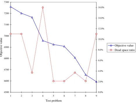
The total area required for all 12 machines is 1469. It should be noted that the total standard blocks within the floor dimensions must be greater than 1469. It should also be noted that either width or length of the floor plan must be greater than or equal to 50, due to the dimensions of machine 9 (50 by 5). Therefore only nine different tests varying the floor dimensions have been studied experimentally. It takes a few hours to search for the best layout solution. Among the layout solutions generated by LADEGA only one solution shows the objective value of 6655.5 with the dead space ratio of 0.021. Figure 6 relatively shows the test problem 8 has the low objective function value and low DSR.
Table 1 shows the comparison of the layout solution shown in Figure 5 and the solution taken in [13]. The changed (either increased or decreased) performance, measured by the size of the LADEGA’s reports compared with other cases, is given in brackets in the Table 1. Welgama and Gibson [13] considered the weights of α = 0.6 and β = 0.4 for the objective value and the dead space ratio respectively, where α +
β = 1. In solving the Wel-6, LADEGA performs 1.9726 times (in overall) better than the construction algorithm proposed by [13] when the above weights are included in a bi-criteria objective model.
Total performance (%) = [(Total performance of the objective function value × α) + (Total performance of the dead space ratio ×β)] × 100 = [1.081 (0.6) + 4.762 (0.4)] × 100 = 255.34 %
5. CONCLUSION
This paper has presented the layout solutions generated by LADEGA for unequal-sized machine layout problems considering pick-up and drop-off (P/D) points. These problems are applicable to cellular manufacturing systems. The P/D points have fixed positions along the
boundaries of machines. It should be noted that these points could be any corners of a machine. A new reference coordinate of the floor plan has been introduced to handle such problems. Two test problems (real case studies) were taken from the literature to solve 6 and 12- machines cases (Wel-6 and Wel-12).
The dimensions of some machines were taken as large as 50 by 5 to demonstrate the performance of LADEGA in handling this complexity. It should be noted that small-size dimensions of facilities are easier than the above large-sized dimensions to be assigned within the floor dimensions.
For the 12-facilities problem, the chromosome 6500
6600 6700 6800 6900 7000 7100 7200 7300
1 2 3 4 5 6 7 8 9
Test problem
Objective value
0.0% 2.0% 4.0% 6.0% 8.0% 10.0% 12.0% 14.0% 16.0%
Objective value
Dead space ratio
length is at least 1500 to represent all the assigned machines as well as dummy facilities. This implies that the computational time for finding very good solutions may be high, say a few hours. Despite this complexity, the layout solutions to the Wel-6 and Wel-12 cases found so far by LADEGA were superior in overall terms to the layout solutions reported in [13]. New mutation and crossover have been proposed and designed to generate feasible layout solutions.
REFERENCES
1. Koopmans, T. C. and Beckmann, M., “Assignment P r o b l e ms a n d t h e L o c a t i o n o f E c o n o mi c Activities”, Econometrica, Vol. 25, (1957), 53-76.
2. Foulds, L. R., “Techniques for Facilities Layout: Deciding Which Pairs of Activities Should be Adjacent”, Management Science, Vol. 29, No. 12, (1983), 1414-1426.
3. Burkard, R. E.; Karish, S. and Rendl, F., “QAPLIB - A Quadratic Assignment Problem Library”, J. Of Global Optimization, Vol. 10, No. 4, (1997), 391-403.
4. Kusiak, A. and Heragu, S. S., “The Facility Layout Problem”, European J. Oper. Res., Vol. 29, (1987), 229-251.
5. S a h n i , S . a n d G o n z a l e z , T . , “ P - C o mp l e t e Approximation Problems”, J. of the Association for Computing Machinery, Vol. 23, (1976), 555-565.
6. Lacksonen, T. A and Enscore, E., “Quadratic Assignment Algorithms for the Dynamic Layout Problem”, Int. J. Prod. Res., Vol. 31, No. 3, (1993), 503-517.
7. Kim, C. B., Kim, S. S. and Foote, B. L., “Assignment Problems in Single-Row and Double-Row Machine Layouts during Slow and Peak Periods”, Computers and Ind. Engng., Vol. 30, No. 3, (1996), 411-422.
8. Kouvelis, P ., Chiang, W. C. and Fitzsimmons, J. , “S i mu l at ed An n eal i n g for Machine L a y o u t
Problems in the Present of Zoning Constraints”,
European J. Oper. Res., Vol. 57, (1992), 203-223.
9. Tavakkoli-Moghaddam, R. and Shayan, E., “Facilities Layout Design by Genetic Algorithms”, Computers and Industrial Engineering, Vol. 35, Nos. 3-4, (1998), 527-530.
10. Krause M. and Nissen, V., “On Using Penalty F u n c t i o n s A n d M u l t i c r i t e r i a O p t i mi z a t i o n Techniques in Facility Layout”, Evolutionary Algorithms in Management Applications, Edited by J. Biethahn and V. Nissen, Springer-Verlag, (1995).
11.
T a v a k k o l i - M o g h a d d a m, R . , “ M a t h e ma t i c a l P r o g r a mmi n g Models for Solving Unequal-Sized Facilities Layout Problems: A Genetic Search Method”, Int. J. of Engineering, Vol. 12, No. 4, (1999), 233-245.12. Montreuil, B. and Ratliff, H. D., “Location Of Input/Output Station within Facilities Layout Optimizing”, Engineering Costs and Prod. Economics, Vol. 14, (1988), 177-187.
13. Welgama, P. S. and Gibson, P. R., “A Construction Algorithm for the Machine Layout Problem with Fixed Pick-Up and Drop-off Points”, Int. J. Prod. Res., Vol. 31, No. 11, (1993), 2575-2590.
14. Heragu, S. S. and Kusiak, A., “Machine Layout: An Optimization and Knowledge-Based Approach”,
Inter. J. Prod. Res., Vol. 28, No. 4, (1990), 615-635.
15. Tavakkoli-Moghaddam, R., “Design of a Genetic Algorithm to Solve Manufacturing Facilities Layout Problems”, PhD Dissertation, Swinburne University of Technology, Melbourne, Australia, (1998).
16. Holland, J. H., “Adaptation in Natural and Artificial Systems: An Introductory Analysis with Applications to Biology, Control, and Artificial Intelligence”, MIT Press, Cambridge (2nd Edition in 1992), (1975).
17. Goldberg, D. E., “Genetic Algorithms in Search, Optimization, and Machine Learning”, Addison-Wesley Publishing Co., (1989).