Research Journal
Volume 8, No. 23, Sept. 2014, pages 53–61
DOI: 10.12913/22998624.1120323 Review Article
Received: 2014.07.29 Accepted: 2014.08.18 Published: 2014.09.09
COMBINED SYSTEMS OF ENERGY GENERATION – A CHARACTERISATION
AND CLASSIFICATION
Jan Gilewski1, Jerzy Montusiewicz2
1 Elektroprojekt S.A., Lublin, Poland, e-mail: [email protected]
2 Institute of Computer Science, Lublin University of Technology, Nadbysrtrzycka 36b, 20-618 Lublin, Poland, e-mail: [email protected]
ABSTRACT
The study presents issues concerning technical solutions of combined systems of en-ergy generation which can be used primarily in low-level power plants, installed in various types of public utility sites. A detailed description is given of selected ways of powering combined energy generation systems, presenting conceptual outlines of their operation and information on their advantages, disadvantages and applications. The following systems are introduced: gas-steam, back-pressure steam turbine, ex-traction-condensing steam turbine, gas turbine, gas microturbine, Stirling engine, fuel cells and internal combustion piston engine. Moreover, the study addresses economic aspects of energy generation in combined systems, discussing different methodologies of cost calculation, including the one used by the European Union. The article also gives a detailed review of piston engine combined-system aggregates available in the Polish market. Type series of associated systems designed for low-power appliances are shown, produced by Polish and foreign companies such as Viessmann, Centrum
Elektroniki Stosowanej CES, H. Cegielski – Poznań, KWE Technika Energetyczna,
TEDOM Poland or the EPS System.
Keywords: Combined Heat and Power (CHP), combined energy generation, cogen-eration systems.
INTRODUCTION
The basic energy carriers such as electricity, heat and cold are produced, both in Poland and in the world, mainly as a result of thermal processes using the chemical energy contained in solid, liq-uid or gaseous fuels. Such energy technologies
should fulfil the following technical-ecological and economic specifications [1]:
• be characterised by the greatest efficiency in
energy processing,
• possess the most advantageous indices of
eco-nomic profitability, i.e. have a short time of in
-vestment return and ensure a high profit value,
• have the least conceivable negative influence
on the environment, i.e. emit a minimum of toxic dusts, gases, noise and waste, using in the process as little water as possible.
The realisation of the above-mentioned goals depends both on the kind of technology of elec-tricity and heat production that we use (e.g. appli-cation of combined or separate systems) and the type of fuel used (e.g. solid, liquid or gaseous).
Combined systems of energy generation using gas module engines are regarded as
dis-tributed generation systems. There is no firmly
grounded and generally accepted terminology in
this regard. According to the CIGRE 37-23 Work
-ing Group (WG 37-23) [2] distributed genera
-tion refers to power sources from 50 to 100 MW
whose construction is not centrally planned. Such sources are not subject to central disposition of power, although in most cases they are part of the distribution network. In Poland the power limita-tion of distributed generalimita-tion systems to 150–200
operation of the distribution network of no more than 110 kV. In practice there are examples of combined systems which are never part of the distribution network and are entirely autonomous systems. This is the situation on boats and ships [3], where the entire energy produced is divided into driving, electric and heating energy.
The notion of combined systems is broader than that of cogeneration systems. The latter pro-duce two types of energy, e.g. electricity and heat, whereas the former can have more energy factors.
Considering the information prepared by the
CIGRE 37-23 Working Group [2], the definition
of combined systems could be generalised. Thus they are small systems of distributed generation
of nominal power of up to 150 MW, or systems
attached directly to distribution networks, or ones localised directly in the consumer’s electric en-ergy network behind the metering and billing system, which produce electricity from original energy (e.g. chemical one) in association with the generation of heat or cold.
The basic task of combined systems is to meet the energy demand of both community and indus-trial consumers. Such systems, known as CHP ones (Combined Heat and Power), belong to the
most efficient technologies of distributed power
engineering and bring numerous technological and ecological advantages. The electricity pro-duced in such systems can be used in a building in its entirety or be partly sold to other consum-ers. On the basis of catalogue data analysis it is
worth mentioning that the general efficiency of a
combined system may reach 90%, while that of a power plant only between 30 and 40%.
Users of combined systems include:
• public utility sites (hotels, office blocks, shop -ping centres),
• sports centres (sports halls, swimming pools and skating rings),
• educational centres (universities, schools), • industrial plants of diverse specialty,
• health service sites (hospitals, out-patient wards, sanatoriums),
• community sites (clusters of single- and multi-family housing, waste treatment plants), etc.
TECHNICAL ASPECTS OF COMBINED
SYSTEMS
A description of different technical solutions of combined systems is given, among other
plac-es, in Kiciński and Lampart [4], as well as in ref -erence [5, 6, 7, 8]. The authors present selected solutions for those systems which can be used in CHP-type arrangements.
Today there are many different kinds of tech-nological solutions of combined systems:
• gas-steam systems,
• with back-pressure steam turbines,
• with extraction-condensing steam turbines, • with gas turbines,
• with gas microturbines, • with Stirling engines, • with fuel cells,
• with internal combustion piston engines, • and others (meeting the criterion of simultaneous
generation of electricity and heat and/or cold).
Gas-steam systems
Combined gas-steam systems serve the gen-eration of heat and electricity in a system of a gas machine (gas turbine) and a steam machine (steam turbine). In gas-steam systems there is an interrelation of the thermodynamic circuits of a gas turbine and a steam turbine via the exhaust waste heat utilised in the heat recovery boiler. Due to this arrangement a hybrid system of
in-creased efficiency is created, combining a
high-temperature circuit realised in a gas turbine with a low-temperature steam circuit [9]. A diagram of the working of a cogeneration gas-steam heat and power plant is shown in Figure 1.
Two types of gas-steam heat and power plants can be distinguished:
• systems working in an open circuit – the clo-sure of the gas fuel circuit takes place via the surrounding atmosphere (air);
Fig. 1. Outline of a cogeneration gas-steam heat and power plant (with a gas turbine and a heat recovery boiler); G – power generator, SP – air compressor, KS – combustion chamber, TG – gas turbine, K – recovery boiler (steam exchanger), TP – steam turbine, S –
• systems working in a closed circuit – in such a system a constant amount of working factor (gas exhaust) keeps circulating.
In view of their high investment costs, in Poland combined gas-steam systems are only used in industrial installations and low-level power industry electrical engineering, in which
they reach capacity between 20 and 200 MW.
Cogeneration systems with gas-steam turbines combine the advantages of gas and steam sys-tems, which causes an increase in the differ-ence of the exit process temperatures (steam) compared to the entrance process (gas exhaust),
which in turn raises the thermal efficiency of
the whole system.
Systems with a backpressure steam turbine A cogeneration system with a back-pressure steam turbine is an example of a cogeneration system of power industry electrical engineering. Such a system has a back-pressure turbine work-ing in a close circuit, supplied by decompressed overheated steam produced in a boiler. Having come through the turbine the steam passes to the exchanger, where it gives off its excess heat to heat up the water in the heating network. A dia-gram of a cogeneration system with a back-pres-sure turbine is shown in Figure 2.
Fig. 2. Outline of a cogeneration heat and power plant with a back-pressure steam turbine; P – fuel, K –
boil-er, TP – steam turbine, G – power generator, W – con
-denser, CW – hot water [4]
Such a system is characterised by a simplic-ity of structure and a relatively low demand for water. A disadvantage is the high dependency between the electricity produced and the de-mand for heat and the exploitation of only high pressures in the production of electricity. Back-pressure turbines as cogeneration systems are
characterised by high total efficiency. The steam
obtained is used for technological and heating
purposes. They are mainly applied in (power) industrial installations.
Systems with an extraction-condensing steam turbine
A cogeneration system with an extraction-condensing steam turbine works similarly to one with a back-pressure steam turbine, but dif-fers by the presence of several heat extractions (several degrees of steam extraction) from the turbine as one goes towards the steam entrance. Such a solution ensures the exploitation of a wider scope of pressures and temperatures in electricity generation.
Just like cogeneration systems with a back-pressure turbine, systems with an extraction-condensing steam turbine are characterised by a
high efficiency of the whole system. They are also
mainly applied in (power) industrial installations in view of the high powers installed and the invest-ment costs. A outline of a system with an extrac-tion-condensing turbine is shown in Figure 3.
Fig. 3. Outline of a cogeneration heat and power plant with an extraction-condensing steam turbine; P – fuel,
K – boiler, TP – steam turbine, G – AC generator, W – heat exchanger, PT – technological steam, WC – hot
water, CH – cooling water [4]
Systems with a gas turbine
Systems with a gas microturbine
Systems with gas microturbines are gas tur-bosystems of small power. Their construction is similar to classical gas turbines except for slight differences. However, their capacity does not sur-pass a few hundred kilowatts.
Just as in a classical gas turbine, a gas micro-turbine is made up of [1]:
• mechanically and thermally connected one-step radial turbines and compressors;
• a regenerative exchanger between the com-pressor and combustion chamber, increasing
the efficiency of the whole system;
• a high speed generator, together with a power-electronic converter system, allowing to adjust the parameters of the energy produced to the demands of the electric energy network.
The advantages of gas microturbines include: • small overall dimensions,
• high efficiency of the whole system,
• reliability of operation and ease of use, • low emission of pollutants,
• ability to supply different fuels (gaseous, liquid), • ability to work in a grid or insular system.
Examples of applications:
• emergency power supply of public utilities
such as offices, hospitals, etc.,
• as a source in distributed energy engineering.
Systems with a Stirling engine
Cogeneration systems with a Stirling engine use reciprocating heat engines with external
com-bustion, which means that the working element – which is the piston moving in the cylinder – is supplied by energy from an external source. Since energy is passed to the system from outside it, it becomes possible to supply such an engine from an arbitrary source of heat. A source of heat can be the process of burning energetic fuel, but also concentrated solar radiation, geothermal energy, etc. At the basis of the operation of a Stirling en-gine lies continuous heating and cooling, that is continuous supply of potential difference of heat to the appropriate zones of the piston in the cyl-inder. A engine works in a closed circuit with any working gas, together with heat regeneration while keeping the gas volume constant (in Carnot’s
cy-cle). Despite the fact that the first copies of those
engines were developed already in the 19th c., such
systems found no general use, but are still within the interest of constructors and scientists.
Systems with fuel cells
Fuel cells are galvanic cells generating elec-tric power from chemical energy on the basis of chemical fuel constantly supplied from outside.
The mass flow of the fuel is correlated with the
current cell load. In contrast to classical galvanic cells, electrodes take no direct part in electro-chemical processes, only steer those processes, therefore their lifespan is theoretically limitless. The lifetime of the electrodes is limited by their structural stability, not chemical one.
In a fuel cell there occurs a direct transforma-tion of chemical energy into electrical one with-out the mediation of heat and limits resulting from the application of Carnot’s circuit, due to which a
Fig. 4. Outline of a cogeneration heat and power plant with a gas turbine: a) open system, b) closed system; PA
– fuel, KS – combustion chamber, TP – gas turbine, G – AC generator, SP – compressor, CW – low-temperature
heat exchanger [1]
high efficiency of the whole process is achieved
[10]. Just as ordinary galvanic cells, it contains two electrodes and electrolyte. The reacting sub-stances (fuel and oxidant) are supplied non-stop. Apart from electrical energy, a product of a fuel cell’s work is heat. The temperature achieved
reaches around 200 ˚C (low-temperature cells) or 1000 ˚C (high-temperature cells) [11]. At present,
both in the USA and in Europe, there are initia-tives to commercialise the production of fuel cells as solutions of distributed cogeneration. Their
ca-pacity reaches some 200 kW. The greatest fuel cell systems achieve the capacity of 11 MW [12]
and are used in power industry.
Systems with internal combustion piston engines
Cogeneration systems with piston engines are characterised by a wide range of rated power, modularity, low capital and investment costs and a short construction and installation time. They
also feature a fast start, flexible keep-up with the load, high efficiency at partial load and high reli -ability. They can be used in objects of wide util-ity as emergency or peak-time sources, but they can also be put to sub-peak or even basic service, providing power, heat or even cold. Their
funda-mental flaws are pollution emitted into the atmo -sphere and noise emission.
Current production includes low-emission engines with spark ignition, powered by natural gas or biogas with a low degree of compression in relation to engines with compression ignition. Such engines are characterised by 60–80% of the power of diesel engines, which ultimately con-tributes to higher investment costs [11]. Yet when powered by natural or biogas, they have lower
pressure in the cylinders and less bearing load, which as a consequence causes a lengthening of exploitation time. Figure 5 shows a outline of a cogeneration system using a piston combustion engine.
The basic cogeneration module using piston engines consists of:
• a system generating electricity (generator) and heat;
• electric safety system; • auxiliary drives switchgear; • installation of automatic oil refill;
• noise mufflers at exhaust and air exits;
• master control cabinet enabling monitoring and visualisation of the operating parameters; • electricity network synchronisation system; • emergency cooling system;
• soundproof enclosure.
A piston engine powered by natural gas, pro-pane or biogas is placed on a common shaft with an asynchronous generator. The work of such a kit enables the production of electricity and heat. As a result of gas combustion the piston engine produces heat as an additional product of energy conversion. Silnik tłokowy zasilany gazem ziem -nym, propanem lub biogazem posadowiony jest
na wspólnym wale z prądnicą asynchroniczną.
The work of such a kit enables the production of electricity and heat. As a result of gas combus-tion the piston engine produces heat as an addi-tional product of energy conversion. This heat is received from the body of the engine and the exhaust expelled, then recovered by the heat ex-changer circuits, added up and by a water or gly-col system transmitted to the receptor. To achieve the assumed temperature of the water or glycol at the output of the module and for a stable
eration of the cogeneration system an auxiliary drives switchgear is used. This switchgear con-trols the valves of the emergency cooling system and continuously monitors the coolant:
• in the case of too hot water at the entrance to the cogeneration system, it redirects part of it to an additional cooling system;
• in the case of too cold water a by-pass is acti-vated, warming it up to a designated tempera-ture.
For CHP modules water parameters are as-sumed at 70 °C at input and 90 °C at outlet [9]. High temperature heat is obtained just from the flue gas at a temperature of 400–600 °C, while the heat obtained from cooling the engine block does not exceed 95 °C [14].
ECONOMIC ASPECTS OF COMBINED
SYSTEMS
Calculating the cost of electricity and heat generation in combined systems in order to as-sess their economic competitiveness can be done by designating the unit cost of production, taking into account the entire period of its existence. The elements of the economic calculation of the com-bined technology of power generation are: • investment costs;
• operating costs, understood as system servic-ing, current supervision, etc.;
• fuel costs;
• the costs of decommissioning at end of life.
In the literature one can find several meth-ods to determine the unit cost of production of electricity and heat, including how this is to be understood in combined systems [11, 12, 15]. In [16] the authors consider the explores the effects of micro CHP systems for energy companies.
One of the criteria for selecting the most ef-ficient design of electricity and heat generation is unit cost. According to the authors of paper [10] discounted long-term unit cost of production in the proposed systems of electricity generation in combined technology can be calculated from equation (1):
(1) where: – discounting factor ;
– discounting factor of the last n-th year of analysis, .
p –discounting rate, or the period of ana-lysis including the period of the object’s construction (b years) and operation (N, e.g. 30 years);
– investment outlay in year t;
–current operating costs (maintenance, renovation and fuel) in year t;
– object value in year N (final, as yet unamortised, value of fixed capital);
–energy generated in year t;
„0” – base (zero) year, or the year of
the first expense or the year of economic
analysis.
A similar methodology for calculating the cost of production of electricity and heat in dif-fuse sources was applied by the European Com-mission in 2008 with the publication of a col-lection of documents under the title: „Second Strategic Energy Review – An EU energy secu-rity and solidasecu-rity action plan”. One of the docu-ments it includes is: “Energy Sources, Production Cost and Performance of Technologies for Power Generation, Heating and Transport”. The method presented can calculate the equivalent unit cost of production of electricity and heat – see formula (2), [15]:
(2)
where: 8760 – ratio equivalent to the number of hours per year;
COE – equivalent unit cost of electricity generation, € / (MW × h);
COH – equivalent unit cost of heat gen-eration, € / toe;
toe – tonne of oil equivalent – energy equiv-alent to one metric tonne of crude oil with a calorific value equal to 10,000 kcal / kg; SCI – individual investment in
manufac-tured facility, € / MW or € / toe;
IDC – interest on capital expenditures during the construction of the facility; CRF – equity installment (return on equity); LF – annual utilisation of the capacity of
the facility;
VOM – equivalent unit variable operating costs , € / (MW × h) or € / toe;
FC – equivalent unit fuel costs, € / (MW × h) or € / toe;
CC – equivalent unit CO2 emission costs, € / (MW × h);
CTS – equivalent unit costs of transport and storage of captured CO2 € / (MW × h) (in the case of energy sources equipped with fa-cilities for CO2 interception and storage).
COGENERATION SYSTEMS USING
PISTON ENGINES
Analysis of the parameters of the produced gas cogeneration units with piston engines re-veals that:
• the largest amount of heat comes from the cooling system of the engine block and the circulation of lubricating oil cooling system; • additional heat is recovered by cooling the
ex-haust gas;
• the amount of heat recovered from the en-gine cooling system, relative to the chemical energy of fuel, represents about 30%;
• the amount of electric power produced relative to the heat is distributed approximately half-in-half, with a slight advantage of the electric power over the thermal power;
• recovered heat is most commonly used for do-mestic hot water.
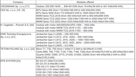
On the basis of analyses of selected manu-facturers’ data sheets it can be stated that systems associated with compression are currently avail-able in a wide power range from about 400 kW to about 5000 kW of electrical power and heat. Therefore, such systems are used primarily where less heat output is needed. They also have limited capabilities in terms of steam generation, but have a higher round-trip efficiency (close to 90%) com-pared to combined systems based on a gas turbine. Currently, the domestic market has several major suppliers of gas aggregate systems com-bined with piston engines, who offer units built with components from different manufacturers. Table 1 shows a list of selected suppliers and their products belonging to so-called small-scale
energy appliances (5 KW to 5 MW [4]).
The features of the above systems include [19]: • control system package;
• handling and visualisation of the functional processes and control by a PC and a touch ter-minal;
• the use of additional control functions (such as adjusting the gas pressure or heat generation); • interconnection, supervision and control of the
multiport systems via Ethernet;
• possibility to connect to a master control sys-tem;
• support of various communication protocols
(e.g. Ethernet, Profibus DP, 3964R, Modbus
RTU);
Table 1. List of firms producing type series of associated systems with combustion engines
Company Modules offered
VIESSMANN Sp. z o.o [17] Vitobloc 200 EM-18/36 … EM-401/549 (from 18 kWe/36 kWt to 401 kWe/549 kWt)
CES Sp. z o.o. [18, 19] MTU Seria 400 (from 119 kWe/198 kWt to 420 kWe/504 kWt)
MTU Seria 4000 (from 772 kWe/872 kWt to 1948 kWe/2156 kWt) MWM Seria TCG 2016 (from 400 kWe/428 kWt to 800 kWe/856 kWt) MWM Seria TCG 2020 (from 1200 kWe/1189 kWt to 2000 kWe/1977 kWt) MWM Seria TCG 2032 (from 3333 kWe/3206 kWt to 4300 kWe/4164 kWt) H. Cegielski – Poznań S.A. [20] module with motor WAUKESHA APG 1000 – 1002 kWe
module with motor MWM TCG 2016 V12C – 600 kWe module with motor MWM TCG 2016 V16C – 800 kWe KWE Technika Energetyczna
Sp. z o.o. [21] Jenbacher type 2 (J208) – 200-300 kWeJenbacher type 3 (J312, J316, J320) – 500-1000 kWe Jenbacher type 4 (J412, J416, J420) – 1000-1500 kWe Jenbacher type 6 (J612, J616, J620, J624) – 2000-4500 kWe Jenbacher type 9 (J920) – 9,5 kWe
TETOM POLAND Sp. z o.o. [22] Micro T7, T30, T50 (from 7 kWe/17,2 kWt to 48 kWe/91,0 kWt)
Cento M50, T80, T100, T120, T160, T180, T200 (from 50 kWe/79,0 kWt to 200 kWe/239,0 kWt) Quanto D400, D580, D770, D1200, D1600, D2000 (from 400 kWe/456,0 kWt to 2000 kWe/2155,0 kWt)
EPS SYSTEM [23] 60 GA (41 kWe/72,8 kWt)
• record of the history of operations and events in the database (from the period of 6 months); • optional remote diagnostics system via ISDN; • option to notify the operator via text messages
/ e-mail (reports, alarms).
An example of a large public utility site using
combined generation with a 1.6 MW piston en -gine is the complex of buildings of Prince Charles Hospital in Brisbane, Australia. The system gen-erates electricity and hot utility water and techno-logical steam [24]. Another interesting example is the designing of combined generation aggregates
for already existing office blocks in Sydney [25].
CONCLUSIONS
The article presents an overview of cogenera-tion systems used in distributed power generacogenera-tion as well as in power industry. Based on the analy-sis of existing design solutions one can make their basic division into those used in the power indus-try and in distributed networks. Due to more at-tention currently paid to environmental issues the boundaries of classical divisions are becoming blurred. At present application systems in power industry are mainly associated with high power ratings, while in distributed power – with low ratings (less than 1 MW, though some move this limit to the value of 5 MW [4]). Installed systems using gas and steam turbines are primarily used in power industry and are characterised by high power ratings – above 1 MW.
Cogeneration systems used in distributed power generation are selected taking into account the characteristics of the object supplied. In the case of power industry, systems supply the na-tional electricity system, which has a relatively rigidly defined parameters and it is not possible to determine the parameters of individual loads received.
In Poland, public utilities are most commonly powered by cogeneration systems using piston engines.
The authors deal with the topic of the article in the context of the multicriterial optimalisation of the selection of combined generation systems with regard to the needs of powering a public util-ity site such as a hospital. Such systems can also be used for powering other utility sites, using – apart from electricity – technological heat, steam and technological cooling. Such a solution, apart from economic effects, can raise the power
gener-ation reliability ratio. Using several units of lower
power can also raise the power generation flex -ibility on a yearly basis, depending on the energy needs of the site powered. Thus the designed as-sociated technologies of energy generation should be characterised by the highest possible capacity, modular structure, scalability and the possibility
of flexible enlargement. Further, they should dis -play the most advantageous indices of economic return, low environmental impact through low emission of dust, gas, sewage and noise, as well as low water consumption.
Associated systems used in dispersed energy production are selected with regard to the load characteristics of the site powered. For an opti-mal choice, different criteria should be used and the whole process should be a multi-stage one. In the case of professional energy production the systems supply the national electricity generation
system, characterised by relatively inflexible pa
-rameters and the lack of the possibility of specifi -cation of reception parameters. Power generation in public utility sites In Poland most often uses combined generation systems with piston engines in the power range of several kilowatts to several megawatts.
REFERENCES
1. Skorek J., Kalina J., Technologie i efektywność ekonomiczna generacji rozproszonej w układach
gazowych. Seminarium cykliczne „Elektroener-getyka w procesie przemian”: – Generacja
rozpro-szona. Gliwice, Politechnika Śląska 2002.
2. Impact of increasing contribution of dispersed
generation on the power system. Working Group
37.23. CIGRE, Paris, February 1999.
3. Ciesielski S., Sroka K., Optymalna eksploatacja
systemu energetyczno-napędowego statku mor
-skiego. [W:] Kulikowski R., Sosnowski J.S. (red.),
Badania systemowe, tom 2, Instytut Badan
Syste-mowych PAN, Omnitech Press, Warszawa 1990.
4. Kiciński J., Lampart P., Cogeneration in a large and
small scale, Kwartalnik Energetyków Acta Ener-getica, 2/2009, 21–28.
5. Thermal Energy Equipment: Cogeneration, Energy
Efficiency Guide for Industry in Asia, 2006, www. energyefficiencyasia.org
6. http://www.facilitiesnet.com/powercommunica- tion/article/How-Cogeneration-Systems-Can-Save-Energy-Costs--10288
7. Mikielewicz J., Micro Heat and Power Plants
Working in Organic Rankine Cycle, Polish J. of
8. By Lindsay Audin, Combined Heat And Power Systems, Building Operating Management, De-cember 2008, http://www.facilitiesnet.com/pow-ercommunication/ article/How-Cogeneration-Sys-tems-Can-Save-Energy-Costs--10288
9. Kotowicz J., Stan i perspektywy rozwoju układów gazowo-parowych. Współczesne problemy roz -woju technologii gazu. Gliwice 2012.
10. Płatek W., Buczak A., Skojarzone wytwarzanie energii elektrycznej i ciepła w oparciu o paliwa
gazowe – agregaty kogeneracyjne. Aspekt technic-zny i ekonomictechnic-zny III FORUM ENERGETYKI,
Białystok, 20 kwietnia 2004.
11. Paska J.: Wytwarzanie rozproszone energii elektry
-cznej z ciepła. Oficyna Wydawnicza Politechniki Warszawskiej, Warszawa 2010.
12. Paska J., Wytwarzanie energii elektrycznej Ofi
-cyna Wydawnicza Politechniki Warszawskiej, Warszawa 2005.
13. Kamiński T., Zagadnienia inżynierskie i ekonom
-iczne związane z produkcją energii w układach ko -generacyjnych Prezentacja Gazoprojekt,
Politech-nika Wrocławska, Wrocław 2011.
14. Figat K., Kogeneracja – Optymalizacja doboru
technologii szansą rozwoju przedsiębiorstwa ciepłowniczego Czasopismo „Instal”, 2011, Tom
nr 10, pp. 14–19, Ośrodek Informacji „Technika
instalacyjna w budownictwie”
15. Energy Sources, Production Cost and Performance of Technologies for Power Generation, Heating and Transport. COM, 2008.
16. Harrison J., Kolin S., Hastevik S.: Micro CHP im-plications for energy companies. COSPP, issue 2, March – April 2000.
17. Combined generation for heat and power produc-tion, Catalogue materials, Viessmann Sp. z o.o., 2012
18. Combined energy generation, Company catalogue card, Centrum Elektroniki Stosowanej CES Sp. z o.o., 2013.
19. Combined Production of Electricity and Heat from Natural Gas. Prospectus promotional. Center for Applied Electronics, CES Sp. z o.o., 2013.
20. Review of combined energy generation. Catalogue
materials, H. Cegielski – Poznań S.A., 2012.
21. Combined generation aggregates with JE
Jenbach-er gas engines, Catalogue matJenbach-erials, KWE Tech -nika Energetyczna Sp. z o.o., 2012.
22. Tedom CHP Units, Catalogue materials,TEDOM Poland Sp. z o.o., 2013
23. Gas combined energy generation aggregates, Cata-logue materials, EPS System, 2013.
24. The Prince Charles Hospital cogeneration project, EcoGeneration — May/June 2012, http://ecogen- eration.com.au/news/the_prince_charles_hospital_co-generation_project/075483/
25. Retrofit of Sydney Building Includes Cogeneration
Plant, October 29th, 2009:

![Fig. 3. Outline of a cogeneration heat and power plant with an extraction-condensing steam turbine; P – fuel, K – boiler, TP – steam turbine, G – AC generator, W – heat exchanger, PT – technological steam, WC – hot water, CH – cooling water [4]](https://thumb-us.123doks.com/thumbv2/123dok_us/8809801.1776675/3.595.307.526.383.514/outline-cogeneration-extraction-condensing-turbine-generator-exchanger-technological.webp)
![Fig. 4. Outline of a cogeneration heat and power plant with a gas turbine: a) open system, b) closed system; PA – fuel, KS – combustion chamber, TP – gas turbine, G – AC generator, SP – compressor, CW – low-temperature heat exchanger [1]](https://thumb-us.123doks.com/thumbv2/123dok_us/8809801.1776675/4.595.118.469.69.232/outline-cogeneration-combustion-chamber-generator-compressor-temperature-exchanger.webp)
![Fig. 5. Outline of a cogeneration circuit using an internal combustion piston engine: P – circulation pump, S – heat exchanger, G – electricity generator [13]](https://thumb-us.123doks.com/thumbv2/123dok_us/8809801.1776675/5.595.124.475.586.744/outline-cogeneration-internal-combustion-circulation-exchanger-electricity-generator.webp)