Copyright © 2012 IJECCE, All right reserved
FPGA Based Network Intrusion Detection System Using
Counting Bloom Filter
Mr. C. Mukuntharaj
Department of ECE PSRR Engineering College for Women,Sivakasi-626140,India Email ID : [email protected]Mrs. M. Lakshmi Karthikeyeni
Department of CSEPSRR Engineering College for Women,Sivakasi-626140,India Email ID : [email protected]
Mr. V. Rajeshkumar
Department of CSE PSRR Engineering College for Women,Sivakasi-626140,India Email ID : [email protected]Abstract – Computer networks face an ever increasing number of threats from hackers, viruses and other malwares. An effective Network Intrusion Detection (NID) is critical before a threat affects end user machines and it leads to many financial and national security problems. As the number of threats and network speed increases, the conventional software based NID system users must choose between protection or higher data rates. As a result there has been a move towards custom hardware implementation of network intrusion detection which can have significantly higher throughput. To ensure the highest throughput bloom filters can be used. Bloom filter is an efficient data structure for hardware-based string matching. Bloom filter offers a mechanism to search for a large number of strings efficiently and concurrently when implemented with Field Programmable Gate Array (FPGA) technology. In this work an innovative architecture to realize string matching algorithm with a hardware accelerator using counting bloom filter have been proposed. The algorithm allows skipping characters not in a match in the text, and in turn simultaneously inspects multiple characters. Bloom filter stores a compact randomized representation of the threat-database, allowing for a number of advantages over traditional hash tables which have a large amount of overhead and require enough memory to store the full threat-database. The basic bloom filter can be improved into a counting bloom filter which allows reprogramming the filter by number of times depends upon the counter value and gives more flexibility. The proposed system will be designed using VHDL (Very High Speed Integrated Circuits Hardware Descriptive Language) and will be implemented using FPGA (Field Programmable Gate Array).
Keywords–Counting Bloom Filter, FPGA, NIDS, VHDL.
I. I
NTRODUCTIONA network intrusion detection system is an intrusion detection system that tries to detect malicious activity such as denial of service attack, port scans or attempts to crack into computers by monitoring network traffic. [4]
NIDS reads all incoming packets and tries to find suspicious patterns known as signatures or rules. These rules are decided by a network administrator while the configuration and deployment of the network intrusion detection system based on the security and network policies of the organization. For instance, if it is observed that particular TCP connection requests connection to a large number of ports, then it can be assumed that there is someone who is trying to conduct a port scan of all/most of the computers of the network. [4]
NIDS is not limited to inspecting the incoming network traffic only. Patterns and outgoing intrusion can also be
found from the outgoing or local traffic as well. Some attacks might also come from the inside of the monitored network, as in trusted host attack. At the heart of every modern network intrusion detection system there is a string matching algorithm.
The NIDS uses the string matching algorithm to compare the payload of the network packet and/or flow against the pattern entries of the intrusion detection rules, which are a part of every network having a network intrusion detection system. String matching needs significant memory and time requirements. In fact, the performance of all network intrusion detection systems depends almost entirely on the performance of the string matching algorithm. For example, the string matching routines in Snort account for more than 70% of the total execution time and 80% of the instructions executed in real time traces. [5]
This paper aims to realize a hardware system to detect network intrusions using counting bloom filter. By using counting bloom filter instead of bloom filter we can get higher throughput and parallelism can be possible in counting bloom filter to improve the performance. The rest of the paper organized as follows. Section II reviews the literature background and existing works. Section III gives the review about the counting bloom filters. Section IV gives the implementation of counting bloom filter in hardware and software level. Section V concludes this work.
II. E
XISTINGW
ORKS ANDL
ITERATUREB
ACKGROUNDA Multiple-string matching algorithm searches the textT= t1,t2,t3,….tn for occurrences of the patterns in a pattern set P={p1,p2,p3….pr} on the same alphabet ∑, where r is the number of patterns. We use m to denote the shortest pattern length and assume │∑│=256 (number of values in a byte).
A.String Matching Algorithms:
The Aho-Corasick(AC) [6] algorithm feeds a finite automaton that accepts the patterns in the pattern set with the input characters one by one, so its time complexity is O(n).
Copyright © 2012 IJECCE, All right reserved of an automaton is compressed to reduce the memory
requirement [16],[17]. Given the wide data bus in modern architectures, tracking one character at a time is inefficient. Several designs can determine the next state after reading a block of characters to boost the performance [7], [8], but they have two drawbacks: 1) Compressing the transition table may need tricky techniques, if feasible, as the table grows with a large block and 2) Because a signature may not start from a block boundary, the match engine should be duplicated several copies at the offset of one more character from the block boundary [8].
The Boyer–Moore (BM) algorithm is the first that can skip characters not in a match based on algorithmic heuristics [15], which are illustrated in [18]. Among the heuristics of the BM algorithm and its derivatives, we specifically mention the bad character heuristic for its relevance to our work. This heuristic matches the characters backward from the suffix of the search window one by one, until either a mismatched character is found or the entire pattern is matched. If a mismatched character is found, the heuristic looks up a table to decide the shift distance of the window according to whether the character is in the pattern or not, and its position. However, the heuristic will significantly decrease the shift distance for a large pattern set due to the high probability of a character appearing in one of the patterns.
The WM algorithm matches a block of characters instead of a character to greatly reduce the chances that a block appears in the patterns. The algorithm assumes equal pattern lengths. If not, it considers only the first m characters of each pattern during the preprocessing and scanning. The search window of
m
characters slides along the text during scanning according to the heuristics: if the right-most block of characters in the search window appears in none of the patterns, a window shift by a maximum m-b+1 of characters is safe without missing any match; Otherwise, the shift value is –j, where the right-most occurrence of the block in the patterns ends at position. If the shift value is 0, i.e., the block is the suffix of some pattern, the occurrence of a true match is verified. The algorithm builds a shift table that keeps the shift values for indexing by the right-most block. Different blocks may be mapped to the same table entry, in which the minimum shift value of them is filled. This mapping saves the table space at the cost of smaller shift values. The worst performance of the WM algorithm may be poor. For example, if a pattern is aaaaa and the text is all a’s, the search window cannot skip any character. The time complexity is O(mn) because the verification takes O(m) in every text position. Nonetheless variants of the algorithm can be found in popular software, such as ClamAV (www.clamav.net) for anti-virus.A Bloom filter compactly stores the patterns in a–bit bit vector for membership queries [14]. For each pattern X , the filter sets to 1 the bits addressed by the K hash values h1(X),h2(X),….hk(X) ranging from 0 to v-1. When a substring in the text is matched, a membership query looks up the bits addressed by W hash values. If one of the bits is unset, W must not be in the pattern set; Otherwise,
verification follows to see whether a true match occurs. The uncertainty comes from different patterns setting checked bits. Properly choosing V and K can control the false-positive rate.
B. Hardware Accelerators
String-matching hardware accelerators either hardwire the patterns into logic cells on field programmable gate array (FPGA) or store them in memory. Updating the patterns in the former may take hours to regenerate a bit-stream and a few minutes to download it onto the chip. Partial reconfiguration can reduce the cost [19]. Besides the reconfiguration cost, the number of available gate counts limits the size of the pattern set. Several examples use this approach. For example, four scanning modules run in parallel to scan multiple packets concurrently in [20], and the throughput is up to 1.184 Gb/s. Cho et al. designed a pipelining architecture of discrete comparators [2]. A pattern match unit involves four sets of four 8-bit comparators to directly compare four consecutive characters in each stage. The matching results from each stage are fed to the next in the pipelining. The design was later enhanced by fully pipelining the entire system [21], and the throughput can be up to 11 Gb/s at 344 MHz, but its area cost is still high. Several following studies were devoted to area reduction, such as [3].
Reconfiguration in memory-based accelerators involves only updating the memory content, and the logics either remain intact or experience only a slight change. The designs may utilize an AC-style automaton [22]–[27], a filtering search window [1-2],[12], [28], or both [8]. Whatever approach they take, a fundamental issue is that if the scanning proceeds by only one character at once, it demands high operating frequency for high speed. Some of them can advance several characters at once by multiple parallel engines, but the available hardware resources restrict the degree of parallelism.
III. C
OUNTINGB
LOOMF
ILTERA.Bloom Filter
A Bloom filter is a data structure which can store the elements of a set in a space efficient manner, if a small error is allowed when testing for elements in the Bloom filter. In this Section the basic properties of Bloom filters are described. In the years after the introduction of the Bloom filter, data structures based on the basic filter were presented by different researchers. These structures are described in next Section.
Basics of Bloom Filter:
Copyright © 2012 IJECCE, All right reserved elements that are not in the table and less space to store
these elements. The drawback of this Bloom filter is that a small error probability is introduced when testing if elements are in the filter.
A bloom filter consists of a bit array of m bits, which are all initially set to 0. Adding the elements of a set S={x1,x2…xn} of n elements is done as follows. For each element xi that is added, k different hash functions h1,h2…hk each with a range {1….m} are used to calculate k different hash values h1(xi)….hk(xi). We assume that these hash functions map each element to the random number uniform over their range. Then, the bits hj(xi) are set to 1 for j=1,2,…k.
When we want to check if a certain element is in our Bloom filter, a similar approach is used as during the addition of elements. The same k hash functions are calculated over the element y. Then we test if the bits hi(y) for i=1,2,….k are equal to 1. If one or more of these bits are still 0, the element is certainly not in the set. If all bits are 1, the element was probably in the set, although there is a small probability that the tested bits were set to 1 due to the addition of different elements.
For large k, using k hash functions demands much computation. In [8] M. Mitzenmacher analyzes the use of linear combinations of two hash functions h1 and h2 to create k new hash-functions. The error-probability f does not increase by this.
B.
Counting Bloom Filter
Counting Bloom Filter is a space efficient probabilistic data structure that is used to test whether an element is a member of a set. It is also an algorithm that can quickly test a membership in a large set by using hash functions into a single array of bits. Selected keywords or string can be easily find using Counting Bloom Filter [I]. False positives are possible, but false negatives are not. The more elements that are added to the set, the larger the probability of false positives [9].
C. Counting Bloom Filter Algorithm:
Programming the Data Base:
An empty Bloom Filter is a bit array of m bits and initially all set to 0. There must also be k different hash function defined, each of which maps or hashes some set element to one of the m array positions with a uniform random distribution.
Fig.2.2: Algorithm of Bloom Filter and Programming of Input R1
Figure 2.2 show programming of input R1. Given input R1, the slider will slide through R1 and then each bit of the R1 will compute k times in hash function. The result will store in database bitmap according to the addresses
corresponding to the hash values. R1 is programmed. Here k=3and m=13.
An input once programmed in the Bloom filter cannot be deleted. This is because deletion of an input requires clearing the corresponding hashed bits. Since a bit can be set by multiple inputs, clearing it will disturb other inputs.
A Counting Bloom filters will be able to solve the problem. This is done by changing the bitmap to array of counters instead of array of bits. Thus the number of corresponding bits can easily increase or decrease. Increment of the corresponding counters show that an input is added. While decrement showed an input is deleted.
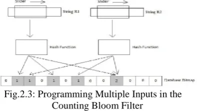
Fig.2.3: Programming Multiple Inputs in the Counting Bloom Filter
If there are multiple inputs, the same procedure is use as shown in Figure 2.3. Input R1 and R2 are being programmed. Note that the bitmap will increase if same address had been found again. Different input can have overlapping addresses. Whenever an input is added to or deleted from the filter, the counters corresponding to the hash values are incremented or decremented, respectively. When a counter changes from zero to one, the corresponding bit in the accumulator is set. When a counter changes from one to zero, the corresponding bit in the accumulator is cleared. It is important to note that the counters are changed only during the addition and deletion of input in a Counting Bloom filter.
Testing the Test Files:
Testing the test files is to verify the membership of the test files. In this example, test 1 and test 2 were used. The procedure is same with programming the Counting Bloom Filter. The same hash function was used and the test files were computed k times. The result was stored in the test file bitmap. If all the result matches the address in the database bitmap, then the test file is a member of the set. If at least one of these bits is not found, then this test file is non-member of the set.
Copyright © 2012 IJECCE, All right reserved Fig.2.4: Querying a Counting Bloom Filter with Multiple
Test File
IV. H
ARDWAREI
MPLEMENTATION OFC
OUNTINGB
LOOMF
ILTERI have proposed a parallel and scalable architecture of network intrusion detection system on FPGA using Counting Bloom Filter algorithm. Two main components in Counting Bloom Filter which is Data path Unit (DU) and Control Unit (CU). DU is Data Path Unit, where the main data processing happened and CU is the controller for the DU.
The data path unit of Counting Bloom Filter consist of four components inside the design which are shift register, hash function, RAM and comparator. The function of the shift register is as a sliding window which will shift every incoming character it receives in a clock cycle. To begin operating this system, character by character of input data will be fed into the shift register. The sliding window will shift one character in a clock cycle. The output will be four characters which is 32-bits width. In this project, XOR hash function will be used. This hash function module will take the 32-bits output from the shift register to become its input. A 12-bits hash value which is the output will be generated by the hashing algorithm. The four character inputs which is 32-bits will hash and become 12-bits output. Notice that the hash out is in unsigned decimal for easy reading. The value of the hash out will never exceed 4096 because 212= 4096 bits. In this project, a comparator is needed. This comparator will take the data from the RAM as input and compare the value with 0. When the data from ram is not 0, the result will set to 1.And if the data is 0, the result will set to 0.
CU is the control unit to control data path unit of Counting Bloom Filter. In this project there are three enable which are en shift, en ram and en comparator. The given table shows the control sequences.
Tab : Control Sequence Table
V. S
IMULATIONR
ESULTSGeneration of Database bitmaps
In hardware based NIDS to compare the data to the signatures we are in-need of database bitmaps that will stored in RAM and compared by the comparator. The database can be generated from the signature definitions. The signature definitions can be easily downloaded from many open source websites. For example we can download the signatures from Clamav site freely. They provide the signatures in daily.cvd and main.cvd files. These signatures are again converted into hexadecimal values and that can be stored in RAM. Part of the memory file from RAM is shown here. The range of the bitmaps is 212= 4096bits. After the hash function, a value which is the address of the input will produce. The value will accumulate inside the bitmaps according to its array location.
Part of database bit map from memory unit
Generation of control sequence for Control Unit
Pseudo Code to Generate Control Sequence:
if (rst =’1’) then y <= s0; elsif (clk’event and clk =’0’) then
case y is
when s0 =>
if start = ’1’ then y <= s1; else y <= s0;
end if;
Copyright © 2012 IJECCE, All right reserved
when s3 => y <= s4; when s4 =>
if nc =’1’ then y <= s4; else y <= s5;
end if;
when s5 => y <= s6; when s6 => y <= s7; when s7 => y <= s8; when s8 => y <= s9;
when s9 => if start = ’1’ then y <= s0;
else y <=s9; end if;
end case; end if;
CU consists of 9 states namely S0 to S9 and the control vector is generated depends upon the state changes. Here the control vectors are used to control the enable signals of Sliding window, RAM and Comparator unit.
Transition Flow of Control Unit
The Fig. shows the transition flow of control unit after simulation in Quartus-II. If more than 4 characters in a text then nc should be set to 1
Data path Unit
Data path unit is used to preprocess the incoming data from the network and make it ready for scanning. Preprocessing consists shifting, generating hash values etc.
Sliding Window
The sliding window will shift every incoming character it receives in a clock cycle. To begin operating this system, the output will be four characters which is 32-bits width.
Hash Function Generator
In this project, XOR hash function will be used. The hash function module will take the 32-bits output from the shift register to become its input. A 12-bits hash value which is the output will be generated by the hashing algorithm.
RAM
RAM is used to store the value of database bitmap. The database can be generated by converting the virus signatures into hexadecimal values. Hash value that generated from the hash function module will be use as memory address to read the data store inside the RAM.
Comparator
Comparator will take the data from the RAM as input and compare the value with 0. When the data from ram is not 0, the result will set to 1.And if the data is 0, the result will set to 0.
Simulation Result of Data Path Unit
Control Unit
CU is the control unit to control data path unit of Counting Bloom Filter. In this project there are three enable signals are used which are en shift, en ram and en comparator.
When start signal is 1 the control signal starts generating the control vector after genrating contol vectors the done signal is set to 1. The design of control unit was based on the control sequence table that is given already.
Simulation Result of Control Unit
Counting Bloom Filter
1.If the data detected in the RAM is 0, then the result will be set to 0. This mean the data is not detected inside the database.
2.If the data detected in the RAM is not 0, then the result will be set to 1. This mean the data is detected inside the database.
Copyright © 2012 IJECCE, All right reserved Simulation Results of Counting Bloom Filter
clk nc rst start
done cv[2..0]
clk en_comp en_ram en_shift read rst shift_in[7..0]
shift_out[31..0] hash_out[11..0] data[11..0] result[11..0] CU:u_CU
DU:u_DU clk
rst start nc
read
done CtrlVector[2..0] input[7..0]
hash_out[11..0] data[11..0] result[11..0] shift_out[31..0]
RTL View of Counting Bloom Filter
VI. C
ONCLUSION ANDF
UTUREW
ORKThe proposed idea of Counting Bloom Filter was designed and implemented. The simulation was done by Quartus–II version 7.2. As per the simulated results the design uses 83 logic elements, 66 registers and 85 pins. Maximum clock frequency of the designed structure was 147.80 MHz with the clock period of 6.766 ns. For this clock frequency we can achieve the network speed (High Throughput) up to 5.46 Gb/s. The worst case through put can be up to 1.2 Gb/s.
The important parameters are compared with the existing technique of counting bloom filter also with the bloom filter and the results are shown in the table given below. Form this table the proposed system can achieve more speed compared to the existing one.
Comparison Table with Existing System
In future the counting bloom filter can be designed to achieve a network speed of 10 Gb/s and above. The memory size should be increased in order to store more signatures database. The reprogramming capacity can be increased by improving the hash function design.
Automatic updates of the signatures databases can be done in order to make the Hardware based NIDS process automatic as in software based NIDS. Also the system can be improved, not only to detect also to prevent the network from various attacks like hacking.
R
EFERENCES[1] Po-Ching Lin,Yin-Dar Lin, et al, (2009) “Realizing a Sub-Linear Time String-Matching Algorithm With a Hardware
Accelerator Using Bloom Filters”., IEEE Trans on Very Large
Scale Integration (VLSI) Systems, Vol.17, No.8, pp.1008-1020. [2] Deke Guo, Jie Wu, et al, (2009) “The Dynamic Bloom Filters”.,
IEEE Trans on Knowledge and Data Engineering, Vol.22, No.1, pp.120-133.
[3] Alex Lukatsky,Protect Your Information with Intrusion Detection. ISBN 1931769117
[4] Wikipedia. Network Intrusion Detection System. http://en.wikipedia.org/wiki/Network_intrusion_detection_syste m
[5] Antonatos S, Anagnostakis K G, Markatos E P. Generating realistic workloads for network intrusion detection systems. Software Engineering Notes, 2004, 29(1): 207-215.
[6] Burton H. Bloom. Space/time trade-offs in hash coding with allowable errors. Comm. of the ACM, 13(7):422.426, 1970. [7] A. Broder and M. Mitzenmacher. Network applications of bloom
filters: A survey. In Proc. of the 40th Annual Allerton Conference on Communication, Control and Computing, pages 636 . 646, Illinios, USA, 2002.
[8] Kirsch Mitzenmacher. Building a better bloom _lter. Unpublished., feb 2005.
[9] Sarang Dharmapurikar, Michael Attig, John Lockwood, Design and Implementation of a String Matching System for Network Intrusion Detection using FPGA-based Bloom Filters, Washington University Department of Computer Science and Engineering, Technical Report WUCS-2004-012. 2004. [12] Christian Esteve Rothenberg, Carlos A. B. Macapuna, F´abio L.
Verdi, and Maur´ıcio F. Magalh˜aes.,IEEE “The Deletable Bloom Filter: A New Member of the Bloom Family”., IEEE vol -14,June-2010.
[13] Ahmed Riadh Baba-ali .,“A High Speed Network Intrusion Detection System Based On FPGA Circuits” IJCSNS
International Journal of Computer Science and Network Security, Vol.9,Nov-2009.
[14] Michael Paynter and Taskin Kocak “Fully Pipelined Bloom Filter Architecture” IEEE.,Vol-12,Nov-2008.
[15] Sarang Dharmapurikar ,Praveen Krishnamurthy, Todd S. Sproull, John W. Lockwood Washington University in St. Louis.
“Deep Packet Inspection Using Parallel Bloom Filters” 2004.
[16] Jared Harwayne-Gidansky, Deian Stefan and Ishaan Dalal.,“FPGA-based SoC for Real-Time Network Intrusion
Detection using Counting Bloom Filters”
[17] Deepti Chaudhary.,“Parallel Processing of Bloom Filter”
International Journal of Electronic Engineering Research Vol.2.,2010.
[18] “Next Generation Intrusion Detection Systems (IDS)” –White Paper From McAfee Network Protection Solutions.
[19] Rebecca Bace, and Peter Mell., “NIST Special Publication on Intrusion Detection Systems”., National Institute of Standards
and Technologies.
[20] Peng Ning, North Carolina State University ,Sushil Jajodia,
George Mason University., “Intrusion Detection Techniques”.
[21] “Guide to Intrusion Detection and Prevention Systems (IDPS)”.,
National Institute of Standards and Technologies.
[22] Jelle Roozenburg.,”A Literature Survey on Bloom
Filters”Research Assignment,Delft University of Technology,8th
November 2005.
[23] Ying-Dar Lin a, Kuo-Kun Tseng et al “A platform-based SoC design and implementation of scalable automaton matching for
Copyright © 2012 IJECCE, All right reserved
[24] Vassilis Dimopoulos*, Joannis Papaefstathiou* and Dionisios
Pnevmatikatost” A Memory-Efficient Reconfigurable Aho-Corasick FSM Implementation for Intrusion Detection
Systems”.,IEEE 2007.
[25] Yang Wang and Hidetsune Kobayashi” High Performance Pattern Matching Algorithm for Network Security”., IJCSNS
International Journal of Computer Science and Network Security, VOL.6 No.10, October 2006.
[26] Hao Chen, Yu Chen*, Douglas H. Summerville” A Survey on the Application of FPGAs for Network Infrastructure Security”.,
Dept. of Electrical and Computer Engineering, SUNY –
Binghamton, Binghamton, NY 13902.
[27] Yaron Weinsberg Shimrit Tzur-David Danny Dolev Tal Anker”
High Performance String Matching Algorithm for a Network
Intrusion Prevention System (NIPS)”, Radlan - a Marvell Company.
[28] Arun Kumar S P.,” High-Speed Signature Matching in Network
Interface Device using Bloom Filters”., International Journal of
Recent Trends in Engineering, Vol 1, No. 1, May 2009.
AUTHOR
’
SPROFILE
C.Mukuntharaj
currently working as Assistant Professor/ECE in PSRR Engineering College for Women, Sivakasi, India. He completed M.Tech in VLSI Design. His research areas are Networking, Vlsi Design & Renewable Energy,
Microprocessor Design. Email ID : [email protected]
M. Lakshmi Karthikeyeni
currently working as Assistant Professor/CSE in PSRR Engineering College for Women, Sivakasi, India. She Completed M.Tech in CSE. Her research areas are MANET & Wireless Networks. Email ID : [email protected]