APPLICATION OF FLOW-THROUGH THREE-DIMENSIONAL
ELECTRODES FOR REGENERATION OF PLATING IRON
ELECTROLYTES: 2. STUDY OF PROCESS REGULARITIES BY
MATHEMATICAL MODELING
Оlga Covaliova
a*, Alexandr Kоshev
b, Valery Varentsov
caState University of Moldova, Research Center of Applied and Ecological Chemistry, 60, A. Mateevici str.,
Chisinau MD 2009, Republic of Moldova
bPеnza State University of Architecture and Construction, 28, G.Titova str., Penza 440028, Russian Federation cInstitute of Solid and Mechanochemistry of the Siberian Branch of RAS, 18, Kutateladze str.,
Novosibirsk 630128, Russian Federation
*e-mail: [email protected]; phone / fax: (+373 22) 57 75 56
Abstract. The main regularities of the electroactive components distribution, polarization and local current density within the depth of the three-dimensional fl ow-through electrode have been studied using the calculation method, in dependence on the overall current density, electrode thickness and degree of its compression, solution fl ow velocity through the electrode, initial concentration of Fe(III) ions in the solution and electrodes brand.
Keywords: three-dimensional fl ow-through electrode, mathematical modeling, numerical calculations, polarization,
local current density.
Introduction
Mathematical modeling [1,2] is one of the effi cient methods allowing to research the regularities of the fl ow-through three-dimensional electrodes operation, including those made of the carbon fi brous materials (CFM). It makes it possible to study the processes occurring within the bulk such electrodes. In addition, this method offers a possibility to predict the effect of the main technological parameters on the studied process and to optimize the electrolysis conditions.
The mathematical model is based on the solution of the system of equations [3], which describe the distribution of the reacting substances concentration, polarization and current inside the pores of the three-dimensional electrode, and involve a series of parameters, which are partly known from the literature data (reaction equilibrium potentials, mass-transfer and diffusion coeffi cients, amount of electrons transmitted during the reaction). Another part of parameters, among which the characteristics of CFM electrodes, their reaction surface, porosity [4,5] can be determined by the experimental methods.
The analytical resolving of the differential equations system is usually diffi cult and is limited by consideration of some particular cases only. Therefore, in our research the numerical computational calculations were carried out, which results made it possible to reveal the regularities of the processes running within the bulk of carbon fi brous electrodes (CFE) during the electrochemical regeneration of iron plating solutions.
Method and conditions of the numerical calculations at the modeling of electrolysis on CFE
During the occurrence of the processes on CFE, the principal mass and charge transfer takes place by the forced convection, when the diffusion and natural convection are negligibly low. Then, according to the mathematical description given in [6], the process of n components reduction within the bulk of porous electrode is described by the following Eq.:
>
@
) ( ) ( 1 ) ( 1 2 1 0 0 x v x FC z e j e e j ɏ j i i M i M M i i i i i, (1)
where jio – exchange current density; ji – polarizing current density; zi – charge of i-th electroactive component (i=1,…,4); F– Faraday’s number, C mol−1; D – diffusion coeffi cient, сm2/s; C
i(x)- concentration of i-th electroactive component
(i=1,…,4); ν(x) – velocity vector of the convection transfer of electrolyte along the axes or linear velocity of electrolyte fl ow,
RT x E x E F z
Mi i i ip
)) ( ) ( ( 1
D and
RT x E x E F z
M i i ip
i )) ( ) ( ( ) 1 ( 2 D .
Here E(x) and Eip(x) is a potential and equilibrium potential for i-th component in a point “x”, accordingly.
Eq.(1) can be presented in another form, once the value ɜ ix i i i r C FD z x
j,lim() is introduced in consideration, which
in the fi rst approximation refl ects the value of limited diffusion density:
>
@
) ( ) ( lim , 0 0 1 2 1 x j e j Pe e e j Pe x j i M i i M M i i i i i (2) where Pei – Peclet number for i-th electroactive component.As it was mentioned earlier, to perform the numerical calculations according to the mathematical model involved, it is necessary to know the values of certain physical and kinetic factors, characterizing the studied system, in which the following reactions can take place: Fe(III)e Fe(II); Fe(II)2e Fe0; 2Н+ →Н
2.
The calculations were performed with regard to the electrolyte, broadly used in practical applications, containing Fe(II) ions (0.5.10-3 mol/L) and Fe(III)ions (0.5.10-4 mol/L). The measured value of the solution electroconductivity made cl =0.14 Ω/сm. As cathodes, the CFM types VINN-250 (ВИНН-250), NТM-100 (НТМ-100), NТМ-200 (НТМ -200), VVP-66-95 (ВВП-66-95), KNM (КНМ), VNG-50 (ВНГ-50), TGN (ТГН) and TVS (ТВШ) were used, for which the known parameters were taken: specifi c reaction surface (Sv, сm2/сm3), electrode electroconductivity (c, Ω/сm) and electrode material porosity (Î) [5,6], and their change with the 2-fold compression was taken in consideration. Such parameters as current density (j, А/сm2) and linear fl ow velocity (u, сm/s) were varied within the defi ned limits for obtaining of the appropriate dependencies.
For the reaction Fe(III)e Fe(II) the diffusion coeffi cient DFe(II) and exchange current j
0 of Fe(II) ions determined from the data of our polarization studies [7, 8], made, accordingly, 0.535∙10-5 сm/s and 0.019 А/сm2. According to the same studies results, the stationery potential of the reaction considered makes ЕFe(III) =+0.643 V. The amount of electrons during the transfer of Fe(III) into Fe(II) is 1, and the transfer coeffi cient of Fe(III) ions, according to [9], is equal to 0.59.
For the reaction of metal iron reducing Fe(II)2e Fe0, the kinetic parameters are: DFe(II) = 0.6∙10-5 сm/s [9]; aFe(II) = 0.43 [9]; z Fe(II) = 2. The value of stationery potential ЕFe(II) = -0.620 V was determined during the polarization studies on the graphite surface [7]. As to the exchange current of Fe(II) ions (jo Fe(II)), for the process limited by the charge transfer stage it was necessary to consider the increase of its value, due to the high CFE surface with the fi bers micro-roughness, with the coeffi cient equal to 100 [4]. Therefore, the value of joFe(II) taken from the literature data [10], was considered to be 2 orders higher and made 1∙10-6 А/сm2.
For the third of possible reactions in the studied system – hydrogen emission, the kinetic parameters were taken as follows: EH2, according to the polarization studies on the graphite surface [7], made -0.83 V; transfer coeffi cient was
2 H
= 0.49 [9]. The exchange current was calculated considering the aforementioned correction with regard to the data [10] and made joH2 = 2∙10-6А/сm2.
Therefore, the processes taken place on the CFE during the electrochemical regeneration of iron plating solution, are accompanied with the formation of the products in the ionic (Fe(II)) or gaseous state (Н2). However, as it was shown [7], with the polarization increase, the electrode potential is shifted to the electronegative fi eld, reaching the values, at which the metal iron is deposited.
It was earlier shown that the presence of oxygen, the reduction-oxidation system is formed in the iron electrolyte, which under the dynamic conditions causes the rapid oxidation of Fe(III) ions to Fe(II) [11]. Our polarization studies has shown [8], that the dependence the of limiting diffusion current value of the reaction Fe(III)e
Fe(II) from the Fe(III) ions concentration is a straight line, which do not pass through the origin of coordinates, but clipping/cutting of a certain segment on the currents’ axis, which may correspond to the current consumed for the reduction of oxygen. (Once the oxygen is removed from the electrolyte solution by the blowing of inert gas, the analogous straight line passes through the origin of coordinates). It is possible that a part of dissolved oxygen which did not react with Fe(III) ions, is involved in this reaction.
Thus, in our calculations we have considered possible electrochemical evolving of oxygen dissolved in water [12]. For the studied process it was supposed that the following electrode reaction with oxygen participation occurs, in which the intermediate product is the adsorbed oxygen atom:
О2→2 Оads.; Оads. + 2Н• + 2е→Н 2О.
The mechanism of this reaction was studied by A.N. Frumkin [13] with regard to the carbon electrodes, possessing high adsorption properties. For this reaction the kinetic parameters are as follows: O2
P
E = 1.1 V; 2 0O
j = 10-8 A/сm2; zO2= 2 [14]. Oxygen concentration was thus taken to be equal to its solubility in water (Т=295 K), which makes
С 2 0
O
= 2∙10-4 mol/L [14].
The results were received in the numerical form, and on their base the graphs have been created, refl ecting the regularities of the electrolysis processes on CFE. Further, the calculated values were compared to the experimental data in order to estimate their convergence.
The results of numerical calculations and their discussions
Effect of current density
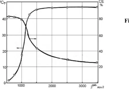
Current density is one of the main technological parameters which allow ensuring the high effi ciency of electrochemical process on CFE. The data obtained by the calculation method (Figure 1) demonstrate that with the increase of the overall current density to 1000 А/m2 the process rate increases sharply and then is stabilized on a certain level. At the same time, the current effi ciency of the target reaction Fe(III)e Fe(II), starting with these current
densities, is decreasing. Such character of the dependencies indicates that equally with the target reaction, the secondary ones occur, resulting in the evolving of hydrogen and depositing of metal iron.
Figure 1. Dependence of the rate of electrochemical reductions of Fe(III) ions to Fe(II) and current
effi ciency on the current density. Conditions: electrode material VINN-250;
SV=560 cm2/g;
= 0.925;S
= 0.4 Ω/сm; L = 0.1 сm; u = 0.1 mL/s;CinitialFe(III) = 8.9∙10-3 mоl/L.
The work of CFE under the conditions of the solution fl ow is connected with the non-uniform distribution of the reacting substances concentration within the electrode depth that is testifi ed by the data on Figure 2.
Figure 2. Distribution of ions Fe(III) concentration along the depth of TDE in dependence on current
density, А/m2:
1 – 200; 2 – 300; 3 – 500; 4 – 1000; 6 – 1500 and 2000, accordingly.
The conditions are the same as related to Figure 1.
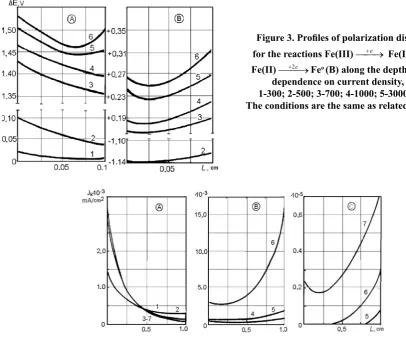
The polarization distribution of reaction Fe(III)
e Fe(II) shown in Figure 3А demonstrates that under the low overall current densities for the low depth electrode, there is an uniform decrease in this value from the back side of the electrode towards the front one. With the increase in jкoverall appears the polarization minimum, which shifts towards the front side. The calculations show that at the jк≈ 1200 А/m2 the limiting current is reached for the reaction Fe(III)e Fe(II), hence, the subsequent increase of jкoverall under the other equal conditions, will not provoke the
increase in this reaction rate.
It was interesting to compare the given dependencies with the polarization distribution for the reaction Fe(II)2e Fe0. It follows from the data of Figure 3B that, as well as for the previous case, the polarization distribution curve is characterized with maximum, which is however located closer to the back side of the electrode. The maximal polarization values are thus reached on the front side of it.
At the same time the distribution of the local current densities along the electrode depth was considered (Figure 4). For the reaction Fe(III)e Fe(II) these values on the back side of electrode surface were
For the reaction Fe(II)2e Fe0 the highest values of the local current densities were characteristic for the front side of the electrode. Within the range jкoverall = 1500-2000 А/m2 this difference between the values of the current on the front and back side of the electrode is insignifi cant, but essentially increases with the increase of jкoverall up to 3000
А/m2 and higher which corresponds to the conditions of the deposition of metal iron.
Figure 3. Profi les of polarization distribution
for the reactions Fe(III)e Fe(II) (А) and
Fe(II)2e Feо(B) along the depth of TDE in
dependence on current density, А/m2:
1-300; 2-500; 3-700; 4-1000; 5-3000; 6-5000. The conditions are the same as related to Figure1.
Figure 4.Profi les of the local current densities distribution of the reactions Fe(III)e Fe(II) (А), Fe(II)2e Feо (B) and 2Н+ + 2е→Н
2 (C) along the TDE depth in dependence on the current densities,
А/m2: 1-500; 2-700; 3-1000; 4-1500; 5-2000; 6-3000; 7 – 5000.
Conditions: electrode material VINN-250 (2-times compressed); SV=560 cm2/g;
= 0.925;S
= 0.4 Ω/сm; u = 0.1 mL/s.As it was shown by calculations (Figure 4B), under jкoverall ≈ 2000 А/m2 and higher under the selected conditions, the hydrogen emission begins, which causes the current consumption for this process. As for the case of the Feо deposition, the current density value is higher on the front side than on the back one, which indicates on the more
intensive hydrogen emission on this side of the electrode. Effect of the electrode thickness and degree of its compression
An important factor infl uencing the process effi ciency on the CFE, is the high reaction surface. The increase of the total surface of these electrodes can be reached by two ways: increase of either their overall size or of their depth.
The second way is rational, as it makes it possible to develop the small-size equipment. However, the increase of the CFE depth has limitations connected with a number of factors, fi rst of all, with the non-uniform distribution of the electrochemical process intensity within the electrode depth, which can be explained by the Ohmic losses. The maximal value of the electrochemical processes effi ciency is determined by the electrode surface working under the conditions of the limiting diffusion current with regard to the ions of the main electroactive component [15].
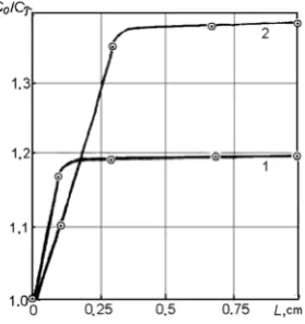
The dependence С0/Сτ from L obtained by calculations (Figure 5) testifi es that the effi ciency of Fe(III) ions reduction to Fe(II) increases with the electrode depth. Once the electrode depth values reach the value of L = 0.1-0.3 сm,
С0/Сτremains constant. This regularity can be explained, knowing the distribution of the reacting ions concentration, current density and polarization within the porous electrode.
Figure 5.Effect of the TDE depth on the change in
Со/Сτvalues in dependence on the overall current
density, А/m2: 1 –500; 2 – 1000. Conditions: electrode material VINN-250;
u = 0.36 mL/s; CinitialFe (III.) = 8.9∙10-3 mоl/L.
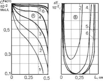
At the low electrode thickness of 0.05 сm (Figure 6, curve 1), the polarization values on the back and front sides are almost the same, inside the electrode being the minimum of polarization. With the increase of L, the non-uniformity of ΔЕ distribution is increased, but in all the cases the polarization on the front side is higher than on the back one. At the same time, ΔЕ values at the internal part of electrode are reduced, approaching to zero. The higher L value, the higher part of the internal surface of electrode has the minimal ΔЕ values, or absence of polarization. The latter fact testifi es that there is no reaction of Fe(III) reaction running on this part of the electrode.
Further increase of the electrode thickness to 2 сm provokes the polarization shift inside the electropositive side, with the appearance of anodic zone (Figure 6, curve 5). Occurrence of the similar anodic zones is described in [17], where their formation is explained with the uniformity worsening of polarization distribution inside the electrode due to the Ohmic losses. In this case in the internal part of electrode the reverse process of Fe(II) ions oxidation to Fe(III) can be running. The calculation results obtained make it possible to suppose that the increase of the electrode thickness above some optimal value will result in the undesired processes, worsening the operation of CFE during the regeneration of iron plating electrolytes.
The curves of polarization distribution for the reaction Fe(II)2e Feо(Figure 6B) have the character similar
to the appropriate curves for the reaction Fe(III)e Fe(II). In follows from these data that under the low thicknesses
of electrodes the probability of Fe(II) ions reduction to metal is increasing, especially on the front side of the electrode, where the polarization is higher.
Figure 6.Profi les of polarization distribution of the
reactions Fe(III)e Fe(II) (А) and
Fe(II)2e Feо(B) with the change of
three-dimensional electrode depth (TDE), cm: 1-0.05; 2-0.1; 3-0.5; 4-1.0; 5-2.0.
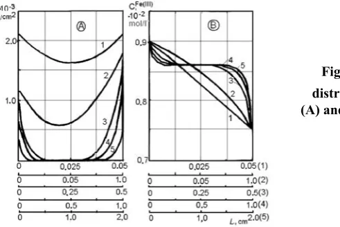
With the increase of L values, the polarization distribution for the reaction considered Fe(III)
e Fe(II) becomes more non-uniform. The profi les of local current density distribution (Figure 7А) are also characterized with the essential decrease of these values in the depth of electrode with the increase of its thickness.This is confi rmed with the data on Fe(III) ions concentration distribution inside the electrode (Figure 7B). It follows from the calculated dependencies that for the conditions selected by us, the maximal value of electrode thickness should not exceed 0.15-0.30 сm. However, in view of the fact that the kinetic and other parameters chosen for the calculations, can differ from the real values, it can be considered that for the practical scopes the electrode thickness can be increased to 0.6-0.9 сm, when its internal surface works intensively enough, or at least is not connected with the decrease in the process rate of Fe(III) ions reducing.
Figure 7. Profi les of the local current densities
distribution of the reactions Fe(III)e Fe(II)
(А) and change in Fe(III) ions concentration (B) with
the change in TDE depth, cm: 1-0.05; 2-0.1; 3-0.5; 4-1.0; 5-2.0.
It was of specifi c interest to assess, with the help of the calculations by the mathematical model, the infl uence of CFE compression degree on studied process. It was found that the maximum process effi ciency is reached when the CFE were 2.0-2.2 times compressed, and above this value the effi ciency was decreased. At the 5-times compression, in spite of the appropriate increase in the reaction surface from 280 to 1400 сm2/g of the material VINN-250 and increase of its electroconductivity from 0.1 to 0.9 Ω/сm, the rate of the process Fe(III)e Fe(II) turned out to be even low,
than for this material in the initial state. In this case the porosity of the material was decreased from 0.97 to 0.83. With the increase of compression up to 2.0-2.2 times, the part of the internal surface, working effi ciently enough, was decreased, and polarization in the depth of the electrode was reduced. The current density distribution is similar to the appropriate polarization changes. However, the values of polarization and current density on the back side are thus increased, which causes the acceleration of the target process under these conditions.
With the 3-times and more increase in the compression degree, the polarization distribution inside the electrode becomes more non-uniform, at the same time its values on the CFE sides are decreased. Correspondingly, the total electrode surface on which the target process runs with the suffi cient rate is reduced.
In this way, the data obtained by calculation method, have shown that the optimal is 2-times compression of CFE, which ensures the highest rates of Fe(III) ions reduction to Fe(II).
Effect of the cathode material
It is known from the literature[5,6], that the commercially produced carbonic-fi brous materials possess various properties, which may render the essential effects on the rates of electrochemical processes, including those running during the regeneration of iron-containing electrolytes. To compare the operation of electrodes made of various types of CFM, it is necessary to study the distribution of polarization, current and concentration within their body.
The results of the numerical calculations of concentration changes within the electrode body (Figure 8А) under the selected electrolysis conditions testify that the most uniformly the studied process runs when the TVS brand of CFM was used. For the other materials the highest process intensity was detected in the proximity of the external sides of electrode. For such materials as VNG-50, VINN-250, NTM-200 the back side was working worse than the front one, whereas for the materials KNM and BBP-66-95 – on the contrary. The materials brands ТGN and NTM-100 have demonstrated the intermediate position in this line, and the curves of concentration distribution are symmetric. The central part of the electrodes, like for the other studied materials (except of TVS), is practically not working.
The calculated data obtained give rise to assumption that the rate of the studied process will be the highest for TVS brand of CFM. For the other studied materials is would be possible to slightly reduce the electrode thickness, without causing the essential effect on process rate, as soon as the internal zones with the insignifi cant polarization were observed for them. This, in its turn, will make it possible to reduce the hydraulic resistance during the electrolyte pumping.
Figure 8. Profi les of Fe(III) ions concentrations
(А) and polarization (B) along the TDE depth in
dependence on the electrode material type: 1-VINN-250; 2-NTM-200; 3-NTM-100;
4-VVP-66-95; 5-ТNG; 6-VNG-50; 7-KNM; 8-TVS.
Conditions: CinitialFe(III) = 8.9∙10-3 mоl/L; u = 0.36 mL/s; joverall.=500 А/m2.
Effect of the initial concentration of Fe(III) ions
The studies of metals electrochemical reducing from low-concentrated solutions has shown [18], that process effi ciency decreases with the increase of the electroactive component concentration. At the same time, there is a range of concentrations specifi c for each process, in which the rate of metal reducing is the highest. Like in the previous cases, this can be confi rmed with the data of polarization and metal ions concentration, as well as current density distribution within the electrode body. It is important to determine these dependencies on the base of the numerical calculations using the mathematical model, as it allows determining the optimal conditions of iron plating solutions regeneration. With the increase of Fe(III)ions concentration up to 8.9∙10-3÷1.8∙10-2 mоl/L, the rate of the studied process is decreasing (Figure 9). However, with the increase of the overall current density to 1500÷3000 А/m2 even under the high concentrations of Fe(III) ions, the high enough reaction rate is reached.
Figure 9.Change of Fe(III) ions concentration
(during the one-time pass through the CFE) in dependence on their initial contents in the electrolyte
under the current densities, А/m2:
1-500; 2-700; 3-1000; 4-2000.
Conditions: electrode material VINN-250 (2-times
compression); u = 0.1 mL/s; L = 0.5 сm.
Distribution of the cathode polarization within the electrode body (Figure 10) also demonstrates the essential infl uence of metal initial concentration: it’s the lower СFe(III)
initial in the solution, the higher is the level of cathode polarization within the CFE depth, and the higher is the effi ciency of these electrodes work. Under the high enough concentration of Fe(III) ions in electrolyte, in the central part of the electrode the minimum polarization is observed, where Fe(III) reduction to Fe(II) practically do not occur. This area is broadening with the increase in Сinitial.
Figure 10. Polarization distribution for the reaction
Fe(III)e Fe(II) under the initial contents in
The study of Fe(III) ions distribution within the electrode has shown that the reduction processes occur only in the near-surface electrode layers, more intensively at the front side. With the decrease of Fe(III) ions concentration, the internal area of electrode, where the reduction of Fe(III) to Fe(II) occurs, is making broader, and under
СFe(III) = 1.8∙10-3 ÷ 5.36∙10-3 mоl/L and j= 500-1500А/m2 the entire depth of the electrode is working at L = 0.5 сm. As follows from the data obtained, at the concentrations of Fe(III) ions of 8.9∙10-2 mоl/L and higher, the thickness of CFE needs to be diminished up to 0.2-0.3 сm, thus decreasing the electrode area where Fe(III) are reduced. At the same time, electrolyte regeneration occurs with the permanent decrease of СFe(III), and with time the internal part of electrode is broadening in which the studied reaction runs. In its turn, this requires to increase the total electrode up to 0.5 сm and higher.
Infl uence of the solution fl ow rate
The rate of the electrolyte fl ow through the three-dimensional electrode is one of the technological parameters, which can be varied in order to modify the rate of the targeted process. With the increase of u values, the rate of Fe(III) reduction to Fe(II) is decelerating (Figure 11), which is caused by the one-time pass of the solution through the electrode body.
However, the results of polarization studies allow supposing that under the conditions of repeated pumping of treated solution through the electrode, the rate of target reaction should be increased, as it is controlled by the diffusion. Therefore, the acceleration of fl ow rate, like the agitation, results in the increase in the limiting diffusion current, thus accelerating the electrode process. The opposite infl uence of this factor detected at the calculations in accordance with the mathematical model, may be connected with the fact that not all the solution fl owing during one-time pass through the CFE, interacts with the electrode surface.
Figure 11.Effect of the solution fl ow velocity on the
reduction of Fe(III) ions to Fe(II) with the change in
current density, А/m2: 1-500; 2-1000; 3-1500.
With the increase of the overall current density up to 1000÷1500 А/m2 the reduction effi ciency of Fe(III) ions is increasing, although the character of dependencies remains the same. At certain part of CFE the limiting current for the target reaction is reached.
It was of special interest to consider the work of the internal area of the electrode (Figure 12). At the fl ow rate 0.05÷0.10 сm/s, the profi le of concentration distribution has a tendency to the continuous decrease from the back to the front side of the electrode, but on a certain portion inside the electrode the rate of Fe(III) ions reducing becomes slower. At the fl ow rate of 0.15 сm/s and higher, the horizontal portions are discernible on the curves, which size increases with the increase in u values. This dependence is correlating with the polarization distribution data along the electrode depth. Thus, at the fl ow rate of 0.07 сm/s through the 0.5 сm electrode, the value of polarization for the reaction Fe(III)e Fe(II) is decreased to minimal, equal to 0.2∙10-3 V, and the minimum is on the ¼ distance of electrode thickness from its back side. With the increase in u values from 0.15 сm/s and higher, the shift of the polarization minimum is observed to the center of electrode, with the simultaneous decrease of its values close to zero. The similar changes undergo also the profi les of current density distribution, consumed for the reaction Fe(III)e Fe(II).
Figure 12. Profi les of Fe(III) ions concentration
In this way, the calculation data show that by decreasing the fl ow rate to certain values it is possible to increase the internal area of electrode where the target process occurs with the suffi cient intensity. From the practical viewpoint, the reducing of fl ow rate makes it possible to reduce the energy consumption for the electrolyte pumping, as well as to reduce its turbulization, so as to prevent the reduction of Fe(II) ions to Fe(III) in the regenerated iron-containing electrolyte by air oxygen.
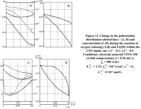
The data given in Figure 13 demonstrate the joint reduction of oxygen and Fe(III). The polarization distribution curve, corresponding to the reaction Fe(III)e Fe(II) (Figure 13В, curves 1,2), at the electrode thickness of 0.1 сm
has a maximum, which at the increase of L values to 0.5 сm is shifted from the front to the back side of the electrode, which is similar to the current density change under these conditions (Figure 13D). With the increase in L values on the part of the electrode, corresponding to the decrease in polarization and local current density, the СFe(III) values are not changed, but then they sharply decrease with the increase of ΔE and j values towards the back side of the CFE.
Figure 13. Change in the polarization distribution (dotted line) - (А, В) and concentration (C,D) during the reaction of oxygen reducing (A,B) and Fe(III) within the
CFE depth, cm: 1,1’ – 0.1; 2,2’ – 0.5. Conditions: electrode material VINN-250
(2-fold compression); u = 0.36 mL/s; jk = 500 А/m2;
EO2
P = 1.1V; j 2
O
o =10-8 A/cm2; z 2 O =2;
CO2
o =2∙10-4 mol/L.
The values of polarization and current, consumed for the oxygen reduction reaction (Figure 13А), are reduced from the back side of CFE to the front one, the polarization distribution having the minimum shifting towards the front side with the increase in L value. With the increase of the electrode thickness, the more intensive oxygen reduction is observed (Figure 14B).
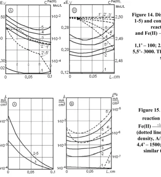
Another side the process with regard to the target reaction of Fe(III) ions reduction to Fe(II) in the iron-plating electrolyte is hydrogen emission. The calculation made for the three-component system, including the reduction of hydrogen ions, shows that the polarization distribution at the reaction occurrence Fe(III)e Fe(II) is characterized
with the decrease of its values from the back to the front side of the electrode (Figure 14). At the low current densities, the polarization changes uniformly the electrode depth, and with the increase of joverall values, the minimum appears in the internal area of the electrode.
The curves of polarization distribution for the reaction Fe(II)2e Feо(Figure 15B) show that the polarization
is higher on the front side of the electrode than on the back one. At the same time, the numerical polarization values for this reaction is lower than for the reaction Fe(III)e Fe(II), which indicates its easier occurrence in the negative
Figure 14. Distribution of polarization (curves 1-5) and concentration (curves 1’-5’) for the
reaction Fe(III) →Fe(II) (A)
and Fe(II) →Fe0 (B) with change in current
density, А/m2:
1,1’ – 100; 2,2’ – 500; 3,3’ – 700; 4,4’ – 1500; 5,5’- 3000. The conditions are similar to those
shown on Figure 13.
Figure 15. Distribution of current for the
reaction Fe(III)e Fe(II) (А) and
Fe(II)2e Feо and hydrogen emission
(dotted line) (B) in dependence on current density, А/m2: 1 – 100; 2 – 500; 3,3’ – 700; 4,4’ – 1500; 5.5’ – 3000. The conditions are
similar to those shown on Figure 13.
Under these conditions, the concentration of Fe(III) is distributed uniformly within the CFE body. With the current density increase, when the side processes start to occur, the СFe(III) distribution within the electrode body is practically not changed. The data of Figure 14B demonstrate that the change of the Fe(II) ions in the electrolyte proceeds uniformly, with the increase in the overall current density, from back to the front side of the electrode.
At the low electrode thickness (0.1 сm), used in our calculations, the curves of the current density distribution, consumed for the reaction Fe(III)e Fe(II), have a tendency to decrease from the back to the front side of the CFE,
although starting with joverall =500 А/m2 and higher, the current density distribution remains unchanged (Figure 15). It was also found that under the current densities below 500 А/m2 under the considered conditions, according to calculations, the hydrogen emission is not running, that can be explained by high overvoltage of its emission on the graphite surface [7]. At joverall =700 А/m2 hydrogen starts evolving mainly on the back side of the electrode, and with the further increase in current density it is reduced within the entire electrode body, on the front side more than on the back one. The curves of current density distribution for hydrogen release reaction have minimum which is placed closer to the back side of the CFE. In this way, running of all the considered reactions has an independent character, the reduction of Fe(III) ions to Fe(II) running more intensively on the back side of the CFE, whereas two other processes connected with the evolving of metal iron and hydrogen on the front side of the electrode.
Conclusions
The calculation results using the mathematical model, regarding the reduction processes in the iron plating electrolytes on the three-dimensional electrodes made it possible to study the effect of the overall current density, CFE thickness and degree of its compression, solution fl ow rate through the electrode, initial concentration of Fe(III) ions in the solution and CFM type on the effi ciency of Fe(III) reduction.
References
1. Varentsov, V.K.; Koshev, A.N. Мathematical modeling of the electrochemical processes in the fl ow-through three-dimensional electrodes. Proceedings of Siberian Branch of Academy of Sciences of USSR, Chemical Series, 1988, 17, pp. 117-125 (in Russian).
2. Koshev, A.N.; Kuzina, V.V. Elaboration and study of mathematical models on non-stationery processes in electrochemical reactors with fl ow-through three-dimensional electrodes. PSUAC: Penza, 2011, 119 p. (in Russian). 3. Koshev, A.N.; Varentsov V.K.; Kamburg, V.G. Mathematical modeling of metals electrodeposition from the
multicomponent systems on fl ow-through three-dimensional electrodes. Proceedings of Siberian Branch of Academy of Sciences of USSR, Chemical Series, 1984, 6(5), pp. 24-27 (in Russian).
4. Daniel-Beck, V.S. On the polarization of porous electrodes. 4. Effect of the solid phase resistance on the potential and current distribution in the electrode. Electrochemistry, 1966, 2(6), pp. 672-677 (in Russian).
5. Varentsov, V.K.; Jerebilov, A.F.; Malei, M.D. Carbonic graphite fi brous materials – new electrodes for metals extraction from the diluted solutions. 1. Nonwoven carbonic graphite fi brous materials. Proceedings of Siberian Branch of Academy of Sciences of USSR, Chemical Series, 1984, 6(17), pp. 120-127 (in Russian).
6. Beck, R.Yu.; Zamyatin, A.P. Mass-transfer coeffi cient and surface of the fl ow-through fi brous electrodes, available for electrolysis. Electrochemistry, 1978, 14(18), pp. 1196-1201 (in Russian).
7. Covaliova, O.V. Electrochemical study of the redox processes in the iron-containing water solutions. Studia Universitatis, Natural Sciences Series, 2009, 21(1), pp. 195-203 (in Russian).
8. Covaliova, O.V. The study of kinetic regularities of Fe(III) ions reduction to Fe(II) in concentrated electrolytes. Studia Universitatis, Natural Sciences Series, 2013, 26(6), pp. 195-203 (in Russian).
9. Sukhotin, А.М. Ed. Reference Book on Electrochemistry. Chemistry: Leningrad, 1981, 488 p. (in Russian). 10. Fetter, K. Electrochemical kinetics. Chemistry: Moscow. 1967, 856 p. (in Russian).
11. Меlkov, M.P.; Namakonov, B.V. On the cathode process of iron electrodeposition. Electrochemistry, 1974, 10(10), pp. 1555-1557 (in Russian).
12. Tarasevich, R.M. Electrochemistry of carbonic materials. Nauka: Moscow. 1984, 253 p. (in Russian).
13. Frumkin, A.N.; Bagotsky, V.S.; Iofa, Z.A.; et al. Kinetics of electrode processes. MSU: Moscow. 1952, 321 p. (in Russian).
14. Bagotsky, V.S. The bases of electrochemistry. Chemistry: Moscow. 1988, 400 p. (in Russian).
15. Beck, R.Yu. Perspectives of application of the electrodes with extended surface in hydrometallurgy. Proceedings of Siberian Branch of Academy of Sciences of USSR, Chemical Series, 1977, 6(4), pp. 11-20 (in Russian).
16. Jerebilov, A.F.; Varentsov, V.K. Experimental study of the polarization distribution along the depth of the fl ow-through three-dimensional electrodes made of the carbonic fi brous materials on the metals electrodeposition. Proceedings of Siberian Branch of Academy of Sciences of USSR, Chemical Series, 1987, 1, pp.19-24 (in Russian). 17. Jerebilov, A.F.; Varentsov, V.K. Experimental prove of the anodic zones presence on the cathode made of the
carbonic graphite fi brous materials. Proceedings of Siberian Branch of Academy of Sciences of USSR, Chemical Series, 1985, 3(8), pp. 35-39 (in Russian).