R E S E A R C H A R T I C L E
Open Access
Toward a 3D coupled atomistic and discrete
dislocation dynamics simulation: dislocation
core structures and Peierls stresses with
several character angles in FCC aluminum
Jaehyun Cho, Till Junge, Jean-François Molinari and Guillaume Anciaux
**Correspondence: [email protected] Civil Engineering Institute, Materials Science and Engineering Institute, École Polytechnique Fédérale de Lausanne (EPFL), Station 18, CH-1015 Lausanne, Switzerland
Abstract
Background: We present a robust method to obtain the displacement field of a dislocation core, which is one of the building blocks for the development of a direct multiscale method coupling an atomistic domain to a discrete dislocation dynamics engine in 3D (e.g. CADD3D).
Methods: The core structure is achieved by modeling of a straight dislocation with an arbitrary mixed angle using atomistic simulation. In order to validate the obtained atomistic core structures, a variational Peierls-Nabarro method is extended to include arbitrary characters.
Results: Both methods show comparable dislocation core structures for all studied angles. We provide also the Peierls stress for a wide range of character angles.
Conclusions: The obtained displacement fields for the dislocation cores were fully validated. These can consequently be employed to construct the described CADD3D coupling scheme.
Keywords: CADD3D; Mixed dislocation; Character angle; Shockley partial; Variational Peierls-Nabarro method; Peierls stress
Background
The understanding of the collective motion of line defects called dislocations is important in order to predict plastic deformations of crystalline materials. This can be studied using several computational tools, including discrete dislocation dynamics (DDD) [1–4]. In DDD, a dislocation is simply represented as a set of nodes connected by straight segments [5]. Due to this simple representation, this method can handle much larger simulation sizes (order of microns) than atomistic simulations (MD), and yields results on sample sizes which are comparable to in-situ TEM experiments [6]. DDD requires several param-eters, which can be obtained from atomistic models, such as a dislocation core energy and nodal mobility law [7]. With these parameters, dislocation dynamics are reasonably well approximated. However, DDD has important limitations which require ad-hoc treat-ments. For instance, dislocation nucleation is only possible by inserting nucleation seeds such as frank-read sources [8–10]. On the other hand, MD describes naturally dislocation
nucleation as it represents dislocations explicitly as crystalline line defects, although the much larger computational cost is an important drawback. Therefore, it is attractive to combine the advantages of both approaches within a multiscale framework.
Currently, several multiscale methods exist including quasi-continuum [11], bridging domain [12] and finite element (FE) combined with atomistic modeling [13]. All these methods couple energies or displacements between two different domains: MD and FE. The authors are developing a 3D direct-coupling method between MD and DDD, which is named CADD3D1and is an extension of the CADD2D [14] approach. In this approach, MD is used where dislocation nucleation are expected (and where DDD would require an ad-hoc treatment), whereas in the remaining zones standard DDD is employed. The key point of the CADD3D method is to deal with dislocations passing seamlessly between these two different domains. One notable difficulty is that a dislocation line can cross the interface between the coupled models. Then, the distinct representation of a dislocation, being either an atomistic structure or a set of DDD segments should match perfectly at the coupling interface. This can be achieved effectively by imposing respective boundary conditions to both MD and DDD regions. In this paper, we focus on the MD boundary conditions imposed by DDD: an adequate position and displacement field matching the MD core structures has to be imposed to all boundary atoms within the influence region of dislocations. The details of this approach, commonly called thecore template tech-nique will be described in Section “Coupled atomistic and discrete dislocations in 3D: core template”. Because the dislocation structure is varying with its character angle2, the
core templateof an arbitrary mixed angle has to be built.
We explain in Section “Coupled atomistic and discrete dislocations in 3D: core tem-plate” the importance of the core template boundary condition for CADD3D to suc-cessfully build the multiscale framework. In order to obtain this core template, we provide comprehensive modeling techniques to create a dislocation with arbitrary char-acter angles (Section “Method 1: Atomistic dislocation modeling”). We also provide an extended variational Peierls-Nabarro (PN) method [15] to validate the obtained MD core structures (Section “Method 2: Variational Peierls-Nabarro method”). Interestingly, the extended PN method can be used to predict core structures of mixed dislocations which cannot be obtained with MD simulations due to limitation of computational cost. With the successful extension of PN method, we show favorable core structures when compared to MD, and analyze the details of dislocation core structures of all the stud-ied character angles (Section “Results 1: Comparison between the MD and PN mod-els core structures”). We also measure Peierls stresses for various mixed dislocations (Section “Results 2: Peierls stresses”), and show that Peierls stresses are largely influenced by the atomistic structures of the dislocation core. Finally, the paper concludes with a discussion on future work towards a fully working implementation of CADD3D.
Coupled atomistic and discrete dislocations in 3D: core template
can handle the development of large dislocation networks at scalable computa-tional cost.3
Even though only plane-strain two-dimensional implementations of CADD exist to date, the method has been successfully used for the study of such problems as dislo-cation emission from crack tips, void growth or nanoindentation in quasistatic (zero temperature) problems [14], fully dynamic problems at finite temperature [16] and inter-mediate problems where finite temperature atomistic is coupled to quasistatic discrete dislocations [17].
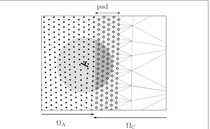
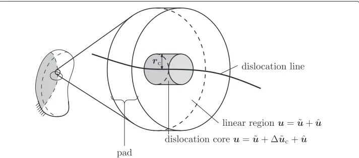
The key impediment to a three-dimensional CADD method is the smooth transition of dislocations across the coupling interface. The stress-strain fields around a dislocation core can be split into a nonlinear core region, where continuum mechanics fails to provide an adequate description and a far-field region, where continuum solutions suffice, see ([5], Chapter 10) or ([18], Chapter 8). While MD simulations handle both the core and the far-field correctly, the continuum with coupled FE and DDD modeling provides accurate strains –and therefore displacements– only for the far-field. As a consequence, spurious forces act on dislocation cores that approach the interface in coupled systems. When a MD dislocation comes close to the interface (see Fig. 1), its (normally) nonlinear core is intersected by the coupling interface. The continuum part of the core (dark gray area in Fig. 1) is constrained to continuum elasticity instead of reacting highly nonlinearly and therefore exhibits exaggerated stresses, leading to a repulsive spurious force on the dislocation.
In order to avoid or at least reduce such spurious forces, we propose the use of so-calledcore templates. The main idea of the dislocation core template is to correct the linear displacement field in the core region by a precomputed empirical and nonlinear displacement field. Theexactcore templateu˜c(x0)for an atom with original positionx0
Fig. 1Dislocation in the vicinity of the interface: the nonlinear core region (schematically represented by the gray area) interacts with the continuum across the interface. The continuum part of the core (dark gray) is linear elastic while the atomistic part is nonlinear, leading to spurious forces.AandCdenote the atomistic
is the error of the plastic contributionu˜(x0)of a dislocation network in a system without elastic strainuˆ(x0)= 0
u˜c(x0)= uA(x0)− ˜u(x0), (1)
= uA(x0)−
j ˜
uj(x0), (2)
where uA(x0) is the exact atomistic solution andu˜j(x0) is the contribution of the j-th discrete dislocation segment. The template is a corrective field for the DDD solution. Assuming that the atomistic solution can be split into individual contributions from the discrete dislocation segments as well
uA(x0)=
j
uA,j(x0), (3)
the template can be expressed in terms of such contributions
u˜c(x0)=
j
u˜c,j(x0)=
j
uA,j(x0)− ˜uj(x0)
. (4)
Far from any dislocation core, non-linear effects become negligible, and the small-strain linear elasticity solutionu˜converges with the atomic solutionuA.
Figure 2 illustrates the application of the template: a dislocation line intersects the interface. Without a template, pad atoms are regular points in a DDD domain and their displacements are given by the superposition of the elastic solutionuˆand the solution due to all dislocation segmentsu˜, see [14]. In order to minimise spurious forces, we dis-tinguish between pad atoms inside the nonlinear dislocation core (gray cylinder of radius
rcin the figure) and pad atoms in the linear elastic region.
The template correction fieldu˜cis added to the pad atoms within the core, suppress-ing spurious forces. A more detailed description of the template can be found in [19]. Two limitations of the template approach are worth mentioning:
• Dislocation spacing:Implicit in the template definition (1) is the assumption that dislocations lines in the pad are spaced far from one another,i.e. no two dislocation
Fig. 2Schematic of dislocation core in the pad. For most of the pad, the liner elastic DDD displacement solution is adequate, in the vicinity of the dislocation line, however, adding the core templateu˜cis required
cores overlap. If this assumption is violated and two dislocation lines approach one another, there will be spurious forces acting on them in the pad.
• Accuracy and simplicity:The template is only useful if it can be precomputed and looked up during the simulation. This means that the displacement field for
dislocation cores with arbitrary character angle and curvature needs to be accurately interpolatable from a finite number of precomputed dislocation cores.
In this paper, we focus on the details of dislocation core structures with respect to the character angle in order to build valid core templates. Consequently, this study starts with a rigorous atomistic modeling of arbitrary mixed dislocations as explained in the following section.
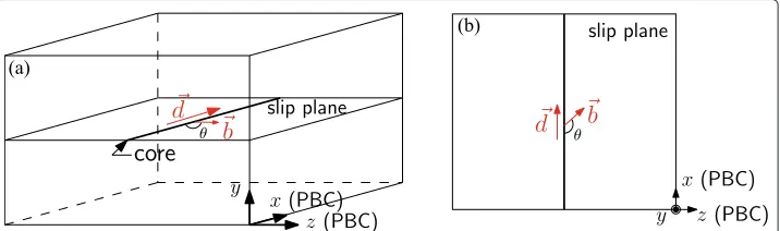
Method 1: Atomistic dislocation modeling
A straight single dislocation can be constructed as shown in Fig. 3. A straight single dislo-cation is inserted in the simulation box having periodic boundary conditions (PBC) both in the dislocation gliding (z) and line (x) directions. As shown in Fig. 3(b), by setting the character angleθ as an arbitrary value, we can model several mixed dislocations. For an edge (respectively screw) dislocation, the dislocation line directiondis defined as per-pendicular (respectively parallel) to the slip direction (Burgers vectorb) on the same slip plane. The edge (90°) and screw (180°) dislocations in FCC are modeled by choosing the dislocation line direction asd =[ 112] for edge and¯ d =[ 110] for screw with the same¯ Burgers vectorb= 12[ 110]. Therefore, in order to create intermediate angle dislocations¯ (90°≤ θ ≤180°), one needs to choose the dislocation line directiondaccordingly. We explain the detailed procedure to find a line directiondfor a specific angle dislocation as shown in Fig. 4.
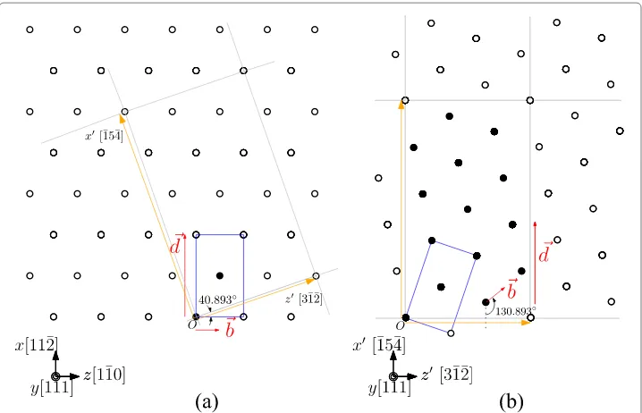
The empty/full circles in Fig. 4(a) are atomistic positions in the slip plane (111). The full circles represent atoms contained in a chosen periodic unit cell, and its replications inxandzdirections generates the other atoms as empty circles. We select one atom in the unit cell as a reference pointO. Then, one of the neighboring atoms ofOindicated by the orange color arrow is chosen as shown in Fig. 4(a), which can be used to con-struct the directionz =[ 31¯2] by connecting it to¯ O. The cross product of they[ 111] andz[ 31¯2] directions gives the remaining lattice coordinate¯ x[15¯ 4] indicated by another¯ orange arrow. Atomistic positions constructed using the new lattice coordinate system (x,yandz) are shown in Fig. 4(b). By choosing the dislocation line inxdirection with
Fig. 4(a) Procedure to find lattice coordinates for a mixed dislocation based on the atomistic representation used for edge dislocation (x=[ 112],¯ y=[ 111] andz=[ 110]). (¯ b) A result of the procedure (x[15¯ 4],¯ y=[ 111] andz=[ 31¯2]). The 130.893° mixed dislocation can be created by choosing¯ xas dislocation line direction. The full black circles are the minimal number of atoms under the given coordinate system, and empty black circles are the result of replications
Burgers vector (b= 12[110]), a mixed (130.893°) dislocation can be modeled. Other neigh-boring atoms, defining otherzaxes, provide lattice coordinates and associated angles for other mixed dislocations. In this study, we have chosen eight representative cases which are presented in Table 1. It shows that the sizes of minimum periodic unit cells vary with the character angles. For example, the 90° (edge) dislocation has the periodic unit cell with dimensionsDX =
√
6a,DY = √
3aandDZ = √
2a, while the size of the unit cell of the 130.893° (mixed) dislocation isDX=
√
42a,DY= √
3aandDZ= √
14awitha=4.056Å (the lattice constant). Therefore, the number of replicas need to be carefully chosen to balance evenly the number of atoms and the length of the simulation box with respect to the desired character angle.
Table 1Selected eight angles, lattice coordinates, number of replicas and atoms of each simulation box
θ(◦) x y z Replicas (x,y,z) Atoms
In order to insert a dislocation with a Burgers vectorb= 12[ 110], we employ the edge¯ and screw Volterra displacement fields (u0x,u0yandu0z) given by [18]
u0x(z,y)= |b|
2π arctan
y z, u0y(z,y)= −|b|
2π
1−2ν 4(1−ν)ln(z
2+y2)+ z2−y2 4(1−ν)(z2+y2)
,
u0z(z,y)= |b|
2π
arctany
z +
zy
2(1−ν)(z2+y2)
(5)
whereνis Poisson’s ratio of the material. For a mixed dislocation, the displacements (u0x,
u0yandu0z) are rotated by the character angleθas
utotal(z,y)=(ux,uy,uz)with
ux(z,y)=u0x(z,y)cosθ,
uy(z,y)=uy0(z,y)sinθ,
uz(z,y)=uz0(z,y)sinθ.
(6)
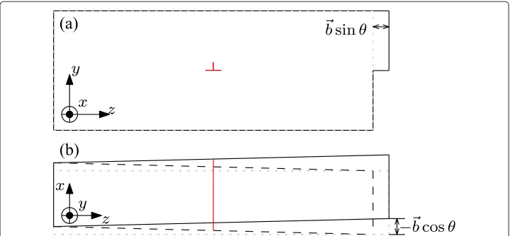
The rotated total displacementutotalis imposed on the perfect crystal. Figure 5 shows the change of simulation box after imposing the displacement. The boxes before and after imposing the fields are represented by the gray dot and black solid (dashed) lines respec-tively. In order to create a straight boundary on the left side of the simulation box in directionz, image dislocations are inserted additionally on the other side ofzdirection. The right side of the simulation box violates the PBC in directionz. This violation can be simply fixed by two additional geometric treatments.
First, the step created by the edge displacement fields (uy anduz) can be avoided by removing the extra plane (a slab of lengthbsinθ). Second, as seen in Fig. 5(b), the oppo-site boundaries in directionzmismatch each other by half of the screw Burgers vector
b/2 cosθ. The dashed black lines are the boundaries of the bottom surface. This mis-match created by the screw displacement field (uz) is fixed by tilting the simulation box with respect to theyaxis in thexdirection by half of the corresponding screw component −b/2 cosθ. Consequently, the PBC in thezdirection is satisfied without any change of
the original elastic displacement field. Finally, the surfaces in theydirection remain free boundaries.
In order to find the equilibrium state of dislocation core structures, the simulation box has to be relaxed. We choose the latest Aluminum EAM potential (Mendelev et al. [20]) to evaluate the inter-atomic forces. The comparison of this potential with other EAM ones will be described in Section “Method 2: Variational Peierls-Nabarro method”. We relax by using a quenching process which is stopped when a norm of forces of all the atoms is below 10−10eV/Å.
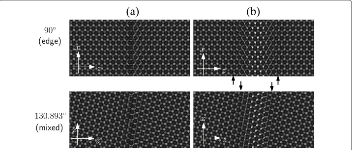
Atomistic structures resulting from the relaxation are shown in Fig. 6 for the cases of 90° and 130.893° dislocations. The atoms are colored by theycoordinates (normal to the slip plane). The initial dislocation line is dissociated into two partial dislocations. After the dissociation, the regions far away from the dislocation core show the black (A)→ → dark gray (B)→gray (C)→white (A) color sequence while the area around the disloca-tion core shows the black (A)→dark gray (B)→white (A)4color sequence. The modified stacking sequence is known as a stacking fault between two Shockley partial dislocations [18] (indicated by the black arrows in the right side of Fig. 6). These partials have dissoci-ated from a perfect dislocation (b= 12[ 110]¯ = b1+ b2withb1= 16[121] and¯ b2= 16[21¯1])¯ due to the energy landscape of the FCC structure. We can see that the stacking fault width for the 130.893° dislocation is smaller than for the 90◦(edge) dislocation. Furthermore, the two partials are symmetric in the case of the edge dislocation, but not for inter-mediate (130.893°) dislocations. In order to understand and validate these relaxed core structures, the variational Peierls-Nabarro model, describing dislocation core structures with a continuum representation, is used in the next section.
Method 2: Variational Peierls-Nabarro method
Continuum theory of linear elasticity provides useful analytic solutions for disloca-tion problems because the theory offers quite accurate dislocadisloca-tion structures when far from the core. However, this theory cannot be employed anymore near the dislocation center, where one finds highly distorted atomistic structures. These nonlinear atomic
interactions can be naturally captured by an atomistic model. For these reasons, simula-tions combining the continuum and atomistic models can be useful not only for the far field but also for the dislocation center. One of the available tools combining the contin-uum and atomistic models is the variational Peierls-Nabarro (PN) method [21, 22], which generally has been used to calculate dislocation core structures by minimizing the total energy of the system. More precisely, the energy in the far field is captured by the energy formulation of continuum linear elasticity theory, while the energy in the core region is obtained by using the crystalline misfit energy and a spread displacement field on the slip plane. The total energy is the sum of both these energy formulations, and the optimal dis-location core structures are found when the total energy is minimum. The PN model is known as a tool providing good descriptions of dislocation core structures in comparison with MD results [5, 15, 23–25].
The original PN formulation starts from the total energyEtot:
Etot=Eel+Emsft,
whereEelis the elastic energy, andEmsftis the misfit energy. Because the original Volterra displacement fielduis singular on the dislocation core, the original energy formulation is ill-posed. Thereforeuhas to be spread, which can be performed in two ways. In a first approach, the displacements are divided into edge uzand screw ux components using several arc-tangent functions [5, 15, 23]. A second method called phase field (PF) method is distributing the displacementuinto all possible slip directionsu1=[ 011],¯ u2=[ 101]¯ andu3=[110] using scalar functions¯ ζ(z)recording the amount of slips [24, 26–28]. In this article, we choose the first approach without comparisons between the two meth-ods because the both methmeth-ods are known to provide sufficiently good dislocation core structures confirming the obtained atomistic simulation results. The two arc-tangent functional forms for both edgeu0zand screwu0xdisplacements as described in [5]:
u0z =A1arctan
z−z1
c1 +
A2arctan
z−z2
c2 −
b
2,
u0x =A3arctan
z−z1
c3 +
A4arctan
z−z4
c4
(7)
whereAk,ckandzkare the parameters obtained through minimization. By the principle of superposition, we rotateu0zandu0xby the character angleθto have slip and line directions inzandxaxes respectively:
uz=
b
π
u0zsinθ−u0xcosθ− b 2,
ux =
b
π
u0xcosθ+u0zsinθ.
(8)
With the arc-tangent shape of displacements in hand (uz and ux), we can construct analytically the elastic energyEel:
Eel= −Kedge
∞ −∞ ∞ −∞ duz dz duz
dz ln|z−z
|dzdz
−Kscrew
∞ −∞ ∞ −∞ dux dz dux
dz ln|z−z
|dzdz
(9)
The misfit energy Emsft can be constructed by using Equation (10) with the misfit potentialsγ (uz,ux)obtained from independent MD simulations. The misfit potentials are computed by constant and rigid shifting of two crystals on the glide plane (111) against each other [29]. The results of misfit potentials of Mendelev et al. [20] potential is shown in Fig. 7(a).
Emsft= −
∞
−∞
γ (uz(z),ux(z))dz (10)
For a dislocation in FCC materials, the generalized stacking fault (GSF) energy curve inx = 112¯directions is important to understand dislocation slip behaviors. The GSF energy curve was first suggested by Vitek [30] to be composed of an intrinsic stacking fault energyγI(ISF) and an unstable stacking fault energyγU (USF) [24, 31]. The ISF energy is the local energy minimum of partial dislocations, and the USF energy is the minimum energy required in order to translate partials. The obtained GSF energy curve inx=112¯ is given in Fig. 7(b) withγU =243.3mJ/m2andγI =128.6mJ/m2. When compared DFT computations and Mishin & Farkas, our selected Mendelev et al. potential provides an accurate description ofγUandγI.
After constructing the total energy formulation, one can see that the only difference between the arbitrary character angles is the amount of elastic energyEel given by the termsKedgeandKscrew(see Equation 9), which differ by 1/(1−ν): the dislocations close to edge have larger elastic energies than the dislocations around screw. The total energy
Etotis minimized numerically to get the optimal shape of the displacement fieldsuover the slip plane.
Results 1: Comparison between the MD and PN models core structures
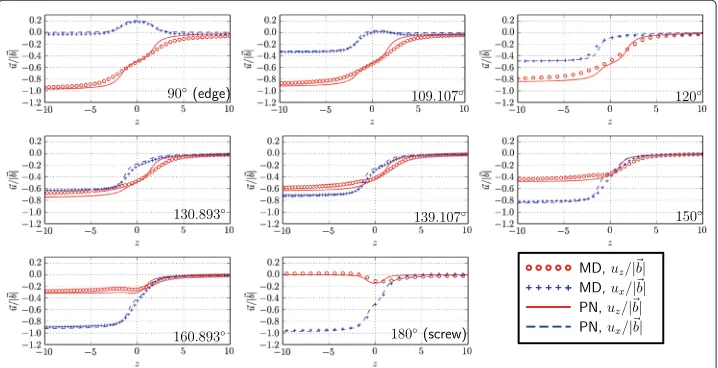
By dumping the displacements of all atoms located on the upper and lower slip planes in the MD simulation, we can compare the displacementsu =(ux,uz)with the PN results
as shown in Fig. 8. The MD results are represented with markers while the PN results are described by lines. Clearly, the PN model predicts well the atomistic dislocation core structures. The edge (90°) dislocation is decomposed into the two symmetric Shockley edge and screw partial dislocations. As the angle increases, the partial displacements are no longer symmetric to each other, and finally become symmetric again at the angle of screw dislocation (180°).
The mapping of PN results onto the perfect atoms located on the slip plane is shown in Fig. 9 with blue crosses in the case of 130.893° dislocations. The equilibrium state of atomistic core structures is represented in red circles. Again, both results are in good agreement in the core region.
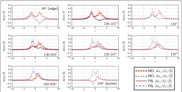
Next, we compare the strains with respect tozcoordinates (du/dz) as shown in Fig. 10. While the strains for the PN results can be derived analytically since the displacements are represented by the two arc-tan functions, the strains for the MD results are obtained by computing the slope between two neighboring points without any line interpolation. We define the stacking fault width as the distance between the strain extremes, thus providing a way to measure the widths as function of the different angles (see Fig. 11). The width for the edge dislocation isl=3.4 Burgers, and it is in reasonable range (2.8≤l≤13.4) when compared to results obtained from other simulations and potentials [32–35]. As the angle increases to screw dislocation (180°), the width decreases smoothly. It can be understood due to the decrease of the elastic energy with increasing angle.
We see that the extended PN method produces dislocation core structures, at much cheaper computational costs, that compare reasonably well with the atomistic core struc-tures. Therefore, we can employ the PN method to predict core structures of mixed dislocations which cannot be obtained by atomistic simulations when the sizes of unit cells become large enough to exclude an atomistic calculation.
Results 2: Peierls stresses
The Peierls stress is defined as the minimum stress required to translate a dislocation at zero temperature [18], and it is known to be influenced by core structures [35–39].
Fig. 9Comparison between MD with PN results with atomistic representation on the slip plane (130.893° mixed dislocation)
Because we have obtained the details of the dislocation core structures e.g., lattice orien-tation and stacking fault widths, the influences of the core structures on the Peierls stress can be studied in this section. Several articles [35, 37, 38] have been published regard-ing the Peierls stresses of FCC Aluminum, measured usregard-ing direct atomistic simulations. A wide range of results (from 1MPa to 13MPa for an edge and from 1MPa to 82MPa for a screw) is observed. Shin and Carter [38] found that a dislocation dissociated into par-tials has a smaller Peierls stress than a compact dislocation. Olmsted et al. [37] studied Peierls stresses for mixed dislocations (120° and 150°) including the edge and screw char-acter angles. They found that the screw and 120° dislocations are required to overcome a higher Peierls energy barrier than the edge and 150° dislocations. They argued that such results are due to the density of atoms in the motion direction (Simmons et al. [39] ini-tially suggested this idea). To the best of our knowledge, Peierls stresses have been studied only for the four character angles (90°, 120°, 150° and 180°), whereas we selected other new character angles.
In Section “Method 1: Atomistic dislocation modeling”, we constructed the dislocations based on the corresponding Volterra displacement fields followed by relaxations. These
Fig. 11 Variation of stacking fault widths for several angles
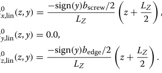
relaxed fields are only valid when dislocations locate at initial positions. As the disloca-tions change their posidisloca-tions on the gliding plane, the following stresses are polluted by the artificial image stresses from the unmatched dislocation surrounding fields [37]. In order to avoid the unwanted effects from the boundaries, we imposed linear displacement fields (ux,lin,uy,linanduz,lin) on the atoms in the top and bottom surfaces instead of the Volterra elasticity solution. By introducing these linear fields, the boundary conditions are invari-ant with respect to the dislocation position. The linear displacement fields for the top and bottom surfaces are chosen as follows:
u0x,lin(z,y)= −sign(y)bscrew/2 LZ
z+ LZ
2
,
u0y,lin(z,y)=0.0,
u0z,lin(z,y)= −sign(y)bedge/2 LZ
z+ LZ
2
.
(11)
withLZ the length of the simulation box in directionz. On the top surface, the nega-tive Burgers (−bedgeand−bscrew) vectors are used, and the positive Burgers (+bedgeand +bscrew) are employed for the bottom surface. In order to consider the mixed character angles, the linear displacements are rotated by the given character angleθ (Equation 6). The remaining atoms are subjected to the Volterra fields, and are also rotated byθ as we described in Section “Method 1: Atomistic dislocation modeling”. After imposing the various displacement fields on the atoms in each region, we relax the simulation box, and measure the Peierls stress through quasi-static loading. Specifically, we translate the atoms on the top surface along the Burgers direction in small steps, while we fix the atoms on the bottom surface. After each translation, we minimize the bulk of atoms and moni-tor the final energy value when the minimization finishes. Therefore, we can observe the energy variation of the system as the dislocation moves to different positions along the gliding direction.
Figure 12(a) shows the dislocation displacement udis in the gliding direction z with respect to the displacements of the top surfaceutop in the Burgers directionb, and the corresponding potential energy variationsEpotof the system are given in Fig. 12(b).
Fig. 12 aDislocation displacements and (b) energy variations with respect to top surface displacement of the edge (90°) and mixed (139.893°) dislocation
larger than the mixed (139.893°) dislocation. Consequently, the edge dislocation requires higher energy accumulations (and reliefs) before (and after) jumps(respectively) as shown in Fig. 12(b) than the mixed dislocation. We call each energy relief and peak pointElpot
andEupotrespectively. The Peierls stress is computed as follows [40]:
σp= E
max pot
bhzLx =
maxEupot,n−1−Epotl,n|n∈[ 1..N]
bhzLx
(12)
whereLxis the length of the simulation box in dislocation line directionxandEpotmaxis the maximum energy release amongN events,hzis the displacement of the dislocation inzdirection occurred by one Burgersbslip. Cai [40] definedhzas the repeat distance for which the system is translation invariant, and argued thathzcan be defined geomet-rically with respect toDz(length of a primitive unit cell in gliding direction). Since the 90°, 120°, 150° and 180° dislocations were built based on the FCC primitive unit cells,hz can be defined ashz=Dz(90°)/4 in the case of FCC crystals. For example,hzis|b|/2 for 90° and 150° dislocations, and√3|b|for 120° and 180° dislocations. These distances are represented in the energy variation curves (Fig. 12) as follows. The energy of the simu-lation box containing a edge (90°) dislocation varies with a periodhz = |b|/2 = 1.43Å. Particularly, the other mixed dislocations (109.107°, 130.873°, 139.107° and 160.893°) are constructed based on the periodic unit cells where several primitive unit cells exist (see Fig. 4). The repeat distanceshz for those angles cannot be defined with respect to the primitive unit cell. Since there are 28 atoms in the given periodic unit cells meaning that 28 energy accumulation-release events happen as a dislocation moves across an entire unit cell. As shown in Fig. 12, the energy of 139.107° dislocation varies periodically byhz=
Fig. 13 Variation of Peierls stresses for the several angles with respect to the density of atoms in the gliding direction. The corresponding Peierls stress value and the character angle are denoted next to each marker
We can first compare Peierls stresses of the dislocations constructed with an equivalent lattice orientation (but with a different character angle). As shown in Table 1, the edge and 150°, 109.109° and 130.893°, 139.109° and 160.893°, 120° and screw dislocations are mod-eled based on the same lattice orientation. For each lattice orientation, the Peierls stress decreases low as the character angle decreases. These observations were confirmed by Simmons et al. [39], and it can be understood with the magnitudes of dislocation dissoci-ation [38]. As seen in the varidissoci-ation of stacking fault widths in Fig. 11, the dislocdissoci-ations are dissociated into larger stacking fault widths when their character angles become small. Consequently, the Peierls stress decreases as the character angle reduces. In the case of 139.109° and 160.893° dislocations, the above argument is not valid, and we have not found any reasons for the discrepancy.
Second, we confirm qualitatively the Peierls stresses of the dislocations between the different lattice orientations as follows. The two dislocations (120° and 180°) based on the lattice orientationx=<110¯ >,y=<111>andz=<112¯>have higher Peierls stresses than the other dislocations. It can be understood with the density of atoms in the gliding direction. We see in Fig. 13 that the densities vary with the lattice orientations of the slip plane. Therefore, the dislocations built within the same family of lattice orientation having small density have high Peierls stresses. Consequently, the 109.107° and 130.893° dislocations have small Peierls stresses compared to the other dislocations.
Conclusion
In this article, we presented one part of the coupled atomistic discrete dislocation formu-lation for the three dimensional case. This important part, the so-called core template, deals with dislocations traversing the coupling interface in order to impose a matching boundary condition to the MD. This template is defined by the core atomistic positions which depend on the character angle. These positions can be obtained by modeling a straight mixed dislocation via an atomistic simulation. The detailed setup of such simu-lations has been extensively described in this paper. Furthermore, based on the extensive modeling results, Peierls stresses have been measured.
the core structures obtained from both methods showed good agreements. The extended PN method can predict displacement fields for any angle, including these that are diffi-cult to obtain with periodic and finite size MD simulations. Furthermore, the measured Peierls stresses were qualitatively confirmed, and we found that the magnitude of disso-ciation and the density of atoms in the gliding direction decide the Peierls stress of the dislocation.
As we already mentioned, these results are directly applicable to the CADD3D imple-mentation to provide matching boundary conditions. However, another important component of CADD3D deals with the dynamic motion of dislocations. Moving dislocations -partially MD and -partially DDD - need to have comparable speeds in order to avoid non-physical spurious forces at the interface. The presented core structures can straight-forwardly be employed as a starting point for simulating MD dislocation motion under shear stress and thus to carry out mobility laws for arbitrary mixed angle.
Endnotes
1Swiss national science foundation project conducted by three principal investigators,
William Curtin, Jean-François Molinari and Guillaume Anciaux.
2Due to plane-strain restrictions, two-dimensional CADD can only handle edge
dislocations.
3Another method, AtoDis [41] has similar properties, but it has not been shown to be
operational in the presence of more than a single dislocation line.
4The stacking falut sequence of the dislocation core region (A→B→A) allows us to
see the second layer of A atoms. These atoms are not seen in the stacking sequence of perfect FCC crystal systems (A→B→C→A).
Competing interests
The authors declare that they have no competing interests.
Authors’ contributions
JC implemented the simulations, and drafted the manuscript. TJ, JFM and GA contributed in the direction of the study and edited the manuscript. All authors read and approved the final manuscript.
Acknowledgments
This work is supported by the Swiss National Science Foundation (grant no. 200021-140506/1).
Received: 29 December 2014 Accepted: 5 May 2015
References
1. Ghoniem N, Tong S, Sun L (2000) Parametric dislocation dynamics: A thermodynamics-based approach to investigations of mesoscopic plastic deformation. Phys Rev B 61:913–927
2. Zbib H, Rubia T (2002) A multiscale model of plasticity. Int J Plast 18(9):1133–1163
3. Verdier M, Fivel M, Groma I (1998) Mesoscopic scale simulation of dislocation dynamics in FCC metals: Principles and applications. Modell Simul Mater Sci Eng 6(6):755
4. Kubin L, Canova G, Condat M, Devincre B, Pontikis V, Bréchet Y (1992) Dislocation structures and plastic flow: a 3D simulation. Solid State Phenomena 23(24):455–472
5. Bulatov V, Cai W (2006) Computer simulations of dislocations. Oxford University Press, Oxford, New York. http://opac. inria.fr/record=b1131935
6. Greer J, Weinberger C, Cai W (2008) Comparing the strength of FCC and BCC sub-micrometer pillars: Compression experiments and dislocation dynamics simulations. Mater Sci Eng A 493(1-2):21–25. Mechanical Behavior of Nanostructured Materials, a Symposium Held in Honor of Carl Koch at the {TMS} Annual Meeting 2007, Orlando, Florida
7. Martínez E, Marian J, Arsenlis A, Victoria M, Perlado J (2008) Atomistically informed dislocation dynamics in FCC crystals. J Mech Phys Solids 56(3):869–895
8. Fivel M, Robertson C, Canova G, Boulanger L (1998) Three-dimensional modeling of indent-induced plastic zone at a mesoscale. Acta Materialia 46(17):6183–6194
9. Robertson C, Fivel M (1999) A study of the submicron indent-induced plastic deformation. J Mater Res 14:2251–2258 10. Chang H, Fivel M, Rodney D, Verdier M (2010) Multiscale modelling of indentation in FCC metals: From atomic to
11. Tadmor E, Ortiz M, Phillips R (1996) Quasicontinuum analysis of defects in solids. Philos Mag A 73(6):1529–1563 12. Xiao S, Belytschko T (2004) A bridging domain method for coupling continua with molecular dynamics. Comput
Methods Appl Mech Eng 193(17-20):1645–1669. Multiple Scale Methods for Nanoscale Mechanics and Materials 13. Kohlhoff S, Gumbsch P, Fischmeister H (1991) Crack propagation in BCC crystals studied with a combined
finite-element and atomistic model. Philos Mag A 64(4):851–878
14. Shilkrot L, Ronald E, Curtin W (2004) Multiscale plasticity modeling: coupled atomistics and discrete dislocation mechanics. J Mech Phys Solids 52(4):755–787
15. Bulatov V, Kaxiras E (1997) Semidiscrete variational peierls framework for dislocation core properties. Phys Rev Lett 78:4221–4224
16. Shiari B, Miller R, Curtin W (2005) Coupled atomistic/discrete dislocation simulations of nanoindentation at finite temperature. J Eng Mater Technol Trans ASME 127(4):358–368
17. Qu S, Shastry V, Curtin W, Miller R (2005) A finite-temperature dynamic coupled atomistic/discrete dislocation method. Modell Simul Mater Sci Eng 13(7):1101–1118
18. Hirth J, Lothe J (1992) Theory of Dislocations. Krieger Publishing Company
19. Junge T (2014) Modelling Plasticity in Nanoscale Contact. PhD thesis, ENAC, Lausanne
20. Mendelev M, Kramer M, Becker C, Asta M (2008) Analysis of semi-empirical interatomic potentials appropriate for simulation of crystalline and liquid Al and Cu. Philos Mag 88(12):1723–1750
21. Burgers J (1940) Geometrical considerations concerning the structural irregularities to be assumed in a crystal. Proc Phys Soc 52(1):23
22. Nabarro F (1947) Dislocations in a simple cubic lattice. Proc Phys Soc 59(2):256
23. Schoeck G (2012) The core structure and peierls potential of dislocations in Al. Mater Sci Eng A 558(0):162–169 24. Hunter A, Beyerlein I, Germann T, Koslowski M (2011) Influence of the stacking fault energy surface on partial
dislocations in FCC metals with a three-dimensional phase field dislocations dynamics model. Phys Rev B 84:144108 25. Ngan A (1997) A generalized Peierls-Nabarro model for nonplanar screw dislocation cores. J Mech Phys Solids
45(6):903–921
26. Denoual C (2007) Modeling dislocation by coupling Peierls-Nabarro and element-free Galerkin methods. Comput Methods Appl Mech Eng 196(13-16):1915–1923
27. Shen C, Wang Y (2003) Phase field model of dislocation networks. Acta Materialia 51(9):2595–2610 28. Shen C, Wang Y (2004) Incorporation ofγ-surface to phase field model of dislocations: simulating dislocation
dissociation in FCC crystals. Acta Materialia 52(3):683–691
29. Zimmerman J, Gao H, Abraham F (2000) Generalized stacking fault energies for embedded atom FCC metals. Modell Simul Mater Sci Eng 8(2):103
30. Vitek V (1968) Intrinsic stacking faults in body-centred cubic crystals. Philos Mag 18(154):773–786
31. Swygenhoven H, Derlet P, Frøseth A (2004) Stacking fault energies and slip in nanocrystalline metals. Nat Mater 3:399 32. Mishin Y, Farkas D, Mehl M, Papaconstantopoulos D (1999) Interatomic potentials for monoatomic metals from
experimental data andab initiocalculations. Phys Rev B 59:3393–3407
33. Hunter A, Zhang R, Beyerlein I, Germann T, Koslowski M (2013) Dependence of equilibrium stacking fault width in FCC metals on theγ-surface. Modell Simul Mater Sci Eng 21(2):025015
34. Kuksin A, Stegailov V, Yanilkin A (2008) Molecular-dynamics simulation of edge-dislocation dynamics in aluminum. Doklady Phys 53(6):287–291
35. Srinivasan S, Liao X, Baskes M, McCabe R, Zhao Y, Zhu Y (2005) Compact and dissociated dislocations in aluminum: implications for deformation. Phys Rev Lett 94:125502
36. Cai W, Bulatov V, Chang J, Li J, Yip S (2004) Dislocation core effects on mobility. In: Nabarro FRN, Hirth J (eds). Dislocations in Solids, vol. 12. North-Holland, Amsterdam
37. Olmsted D, Hardikar K, Phillips R (2001) Lattice resistance and Peierls stress in finite size atomistic dislocation simulations. Modell Simul Mater Sci Eng 9(3):215
38. Shin I, Carter E (2013) Possible origin of the discrepancy in Peierls stresses of FCC metals: First-principles simulations of dislocation mobility in aluminum. Phys Rev B 88:064106
39. Simmons J, Rao S, Dimiduk D (1997) Atomistics simulations of structures and properties of12(110) dislocations using three different embedded-atom method potentials fit toγ-TiAl. Philos Mag A 75(5):1299–1328
40. Cai W (2001) Atomistic and Mesoscale Modeling of Dislocation Mobility. http://dspace.mit.edu/bitstream/handle/ 1721.1/8682/49725239-MIT.pdf
41. Brinckmann S, Mahajan D, Hartmaier A (2012) A scheme to combine molecular dynamics and dislocation dynamics. Modelling Simul Mater Sci Eng 20(4):045001
42. Angelo J, Moody N, Baskes M (1995) Trapping of hydrogen to lattice defects in nickel. Modell Simul Mater Sci Eng 3(3):289
43. Voter A, Chen S (1987) Accurate interatomic potentials for Ni, Al and Ni3Al. Proc MRS Fall Symp 82:175–80 44. Oh D, Johnson R (1988) Simple embedded atom method model for FCC and HCP metals. J Mater Res 3:471–478 45. Hartford J, Sydow B, Wahnstroem G, Lundqvist B (1998) Peierls barriers and stresses for edge dislocations in Pd and
Al calculated from first principles. Phys Rev B 58:2487–2496
![Fig. 7 (energy curves inwas taken with agreement of copyright by author [29, 46] and IOP publishing)](https://thumb-us.123doks.com/thumbv2/123dok_us/9585723.1941243/10.595.119.478.488.674/energy-curves-inwas-taken-agreement-copyright-author-publishing.webp)