ORIGINAL ARTICLE
An Iterative Compensation Algorithm
for Springback Control in Plane Deformation
and Its Application
Rui Ma
1,2, Chunge Wang
3,4*, Ruixue Zhai
1,2and Jun Zhao
1,2Abstract
In order to solve the springback problem in sheet metal forming, the trial and error method is a widely used method in the factory, which is time-consuming and costly for its non-direction and non-quantitative. Finite element simu-lation is an effective method to predict the springback of complex shape parts, but its precision is sensitive to the simulation model, particularly material model and boundary conditions. In this paper, the simple iterative method is introduced to establish the iterative compensation algorithm, and the convergence criterion of iterative parameters is put forward. In addition, the new algorithm is applied to the V-free bending and stretch-bending processes, and the convergence of curvature and bending angle is proved theoretically and verified experimentally. At the same time, the iterative compensation experiments for plane bending show that, the new method can predict the next compen-sation value based on the springback of each test, so that the target bending angle with the error of less than ± 0.1% and the target curvature with the error of less than 0.5% are obtained after 2‒3 iterations. This research proposes a new iterative compensation algorithm to predict springback in sheet metal forming process, where each compen-sation value depends only on the iteration parameter difference before and after springback for the same forming process of same material.
Keywords: Springback control, Iterative compensation algorithm, Convergence criterion, V-free bending, Stretch-bending
© The Author(s) 2019. This article is distributed under the terms of the Creative Commons Attribution 4.0 International License (http://creat iveco mmons .org/licen ses/by/4.0/), which permits unrestricted use, distribution, and reproduction in any medium, provided you give appropriate credit to the original author(s) and the source, provide a link to the Creative Commons license, and indicate if changes were made.
1 Introduction
Springback can change the shape and dimensional accu-racy of sheet metal forming parts, particularly bend-ing and shallow drawbend-ing parts, resultbend-ing in subsequent quality and assembly problems. Thus, springback is one of the key issues in designing the bending die and pro-cess parameters. If the springback rule is not adequately grasped, it has to repeatedly “trial and error” to obtain the desired accuracy, or to reshape the formed piece, leading to prolonged production cycle and increased costs. For example, in the US automotive industry alone, more than $50 million is lost each year for this reason [1].
Therefore, springback is not only a long-term hotspot in academia, but also a problem in industrial production.
The purpose of springback research is to realize the effective control of springback, which can be achieved by two methods, namely, process control and tool surface compensation control.
Process control method is to control the springback by optimizing the forming process, such as controlling the blank holder force and punch stroke [2, 3], changing the loading method [4–6], increasing the forming steps [7, 8], and improving the forming temperature [9–11].
Process control method can reduce springback to some extent, but can not completely eliminate springback in theory. Therefore, for high precision stamping products, process control method is still unable to meet the spring-back control requirements, then we need to consider the second method, that is the tool surface compensation control method. Specifically, according to the predicted
Open Access
*Correspondence: [email protected]
3 College of Mechanical and Energy Engineering, Ningbo Institute
or measured springback value, the tool surface is modi-fied so that the shape of the part after springback approx-imate that of the design requirements. Traditionally, this approach is trial-and-error method, which is time-con-suming and costly for its non-direction and non-quanti-tative. Based on finite element analysis and semi-analytic method, several springback compensation algorithms have been developed to improve efficiency of controlling springback in the past few years. Among them, the “Force Descriptor Method (FDM)” [12, 13] and “Displacement Adjustment (DA) method” [1] have attracted research-ers more attention for its directness and effectiveness. Recently, various methods have been reported based on the DA method or the FDM, such as the Smooth Dis-placement Adjustment (SDA) method and the Surface Controlled Overbending (SCO) method [14], the Accel-erated Compensation (AC) method [15], the Compre-hensive Compensation (CC) method [16], the Enhanced Displacement Adjustment (E-DA) method [17], the alter-nate Hybrid Method (HM) [18], the Discrete Curvature Adjustment (DCA) strategy [19], and the Sheet Elements Compensation (SEC) method [20]. Most of these meth-ods are based on finite element simulation and focused on optimizing the compensation direction by the com-pensation factor as well as smoothing the plane by the function curve, to improve the compensation speed and convergence. At the same time, the material model has also been studied by many researchers to improve the accuracy of simulation and theoretical prediction [21, 22].
It’s a fact that these improved DA methods or FDM take coordinate deviation of the mesh nodes or strain distribution in the bending pieces as the characterization to control the springback. Finite element simulation is an effective method to solve engineering problems, which has a certain advantage to solve the springback of com-plex shape parts. However, its precision is sensitive to the simulation model [23], particularly material model [24], element type [25], boundary conditions [26] and other input parameters, leading to the uncertainty in the tool compensation. The accurate calculation model has not yet been established, although the theoretical analysis can analyze the trend of the iterative parameters [27–29]. In addition, the physical test can determine the error between the current parameter and the target, but con-fused about the compensation value for the next step.
For ordinary metal materials, the larger the deforma-tion, the greater the springback, which is premised on other deformation conditions remain constant. Inspired by this fact, a new iterative compensation method of spring-back control in plane bending is proposed in this study and applied to the V-free bending and stretch-bending
processes. The convergence and compensation process of iterative parameters are studied by theory and experiment.
2 Iterative Compensation Algorithm
2.1 Introduction of Simple Iterative Method
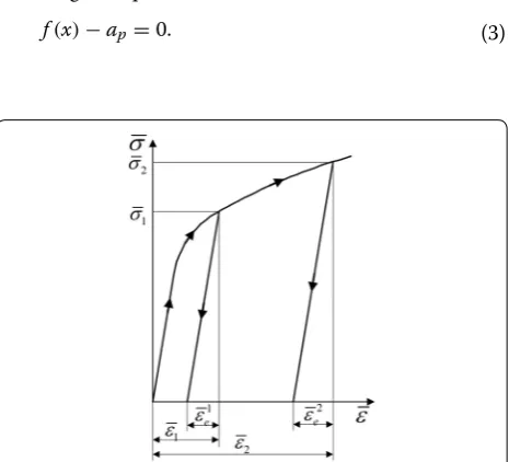
In the analysis of the factors that affect the springback, Wang [30] pointed out that the greater the bending center angle α , the greater the length of the deformation zone, the greater the springback value, the greater the springback angle �α . Similarly, Zhong [31] also summed up that in the same degree of deformation, the greater the bending center angle α , the greater the amount of springback. In addition, according to the equivalent stress-strain relationship in the elastic–plastic deformation shown in Figure 1, the spring-back ε¯2e produced by the larger equivalent strain ε¯2 is obvi-ously larger than the springback ε¯1e produced by the larger equivalent strain ε¯1 . Therefore, for ordinary metal
materi-als, the larger the deformation, the greater the springback on the premise of maintaining deformation conditions, which is the theoretical basis of this paper.
Let x be the value of the control parameter before spring-back, and f(x) is the function expression between the control parameters before and after springback, then the springback value �(x) can be expressed as
According to the above theoretical basis, if �(x) is a monotonically increasing function, that is �′(x) >0 , then
there is
The purpose of springback control is to determine a parameter value a , that changes to ap after springback, that is, solving the equation
(1) �(x)=x−f(x).
(2) f′(x) <1.
(3) f(x)−ap=0.
For this reason, the simple iteration method is intro-duced. According to the thought of solving equation, the iterative equation is constructed as
Combined with Eq. (2), it can be deduced that
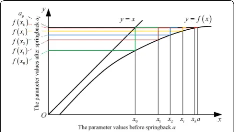
The iterative equation Eq. (4) is convergent by the local convergence theorem of simple iterative method, that is, where x∗ satisfies x∗=ϕ(x∗) . Thus, as shown in Fig-ure 2, the initial value is chosen as ap , then the iterative sequence is obtained according to the iterative equation as
For a pre-set error ε , when xk−xk−1
≤ε , it is recog-nised that x∗≈xk , then f(x∗)−ap=0 is the request.
For the springback control problem, if the relation function y=f(x) of the parameters before and after the springback satisfies f′(x) <1 , the iterative compensa-tion method can be used to control the parameters to converge to the target value. Therefore, for the compen-sation calculation of the springback problem, Eq. (2) can be used as the convergence criterion of the selected parameters, and this convergence method is applicable to parameters that are smaller after springback, such as cur-vature and bending angle.
(4) x=x+ap−f(x)=ϕ(x).
(5)
ϕ′(x)<1.
(6)
x0=ap,
x1=x0+ap−f(x0),
x2=x1+ap−f(x1), .
. .
xi =xi−1+ap−f(xi), .
. .
xk =xk−1+ap−f(xk).
At present, all the theoretical solutions of springback are failed to establish the exact calculation model, while its prediction for the trend of the parameter is credible. The test can give the error of the current parameter and the target, but the next compensation is difficult to be determined for lack of theoretical guidance. Based on the theoretical analysis of f′(x) <1 , the iterative compensa-tion algorithm proposed in this paper can determine the convergence of the control parameters, and then deter-mine the next compensation based on the springback value of each test.
2.2 A General Iterative Compensation Algorithm for Springback Control
For a general springback problem, it is too hard to deter-mine the function relationship y=f(x) . Therefore, this paper establishes a generalized iterative compensation algorithm for springback problem by means of trial and error method. In particular, the iterative compensation mechanism of the springback control is described as fol-lows: for the springback problem of the general stamping process, a process parameter is first determined, which is smaller after springback and has iterative convergence according to the local convergence theorem, then finite compensation experiment is carried out by the iterative compensation algorithm, so that the control parameter is gradually approached to the target value until the accu-racy requirement is met.
As shown in Figure 3, after the convergence is con-firmed, in order to obtain the workpiece with the param-eter value of ap , the iterative compensation method is used to determine the value a before springback, that is the tool surface parameter, as follows:
Step 1: Ready. Determining the initial value, usually the target value x0=ap;
Step 2: Iteration-Forming. Stamping to obtain the springback value;
Step 3: Control-Modify. Checking x1−ap, if
x1−ap≤ε ( ε is the dimensional accuracy), the iteration is terminated, and a=x0 ;
oth-erwise,
x1−ap
is taken as the compensation value, and the die surface parameter is modi-fied as x0=x1+x1−ap , go to Step 2;
Figure 2 Parameter relationship before and after springback based
Step 4: Output. When
x1−ap
≤ε, the iteration ter-minates and the correction end. a=x0 is the parameter value of the final tool surface.
By means of mathematical analysis, the iterative com-pensation algorithm of springback control provides the theoretical basis for tool surface modification. The finite compensation calculation can reduce the error of the process parameters and guide the tool surface correc-tion direccorrec-tion. In addicorrec-tion, each compensacorrec-tion value is only related to the difference of the iteration parameters before and after springback, and has nothing to do with the material properties and mechanical model, so this springback control method is more versatile.
As repeatedly mentioned above, the precondition of the iterative compensation algorithm is to determine the iterable parameters with convergence. Therefore, the springback process of V-free bending and stretch-bend-ing processes will be analyzed and the convergence of the relevant process parameters will be discussed.
3 Iterative Convergence of Bending Process Parameters
3.1 Basic Assumptions
(1) The cross section is always planar and perpendicu-lar to the neutral layer;
(2) The blank is approximately unidirectional stress-strain state;
(3) The strain is linearly distributed and satisfies:
where ε is the strain; y is the distance from the par-ticle to the geometric neutral layer; and ρ is the bending radius of the geometric neutral layer. (4) The material properties are in accordance with the
bilinear hardening model, that is
where σ is the stress, ε is the strain, E is the elastic modulus, D is the plastic modulus, and σs is the
ini-tial yield stress.
(7)
ε= y
ρ,
(8) σ =
Eε, 0≤ε≤εs,
σ0+Dε, ε > εs
(9)
εs= σEs,
σ0=σS
1− D E
,
(5) The cross-section of the sheet is rectangular, whose cross-sectional area and moment of inertia are A=bt and I= 121bt3 , where b and t are the width and thickness of the sheet, respectively.
3.2 V‑free Bending Process
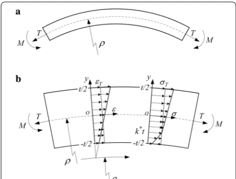
Under the action of bending moment M, the blank with rectangular cross-section is bent and springback after unloading. In addition to the above basic assumptions, this section supplements one, that is, the stress neutral layer, strain neutral layer and geometric center layer of the sheet always coincide. The geometrical relationship before and after springback is shown in Figure 4(a). Now set: after bending, the radius of the neutral layer is ρ, the curvature of the neutral layer is K, the bending angle is α, the supplementary angle is β; after the springback, the radius of the neutral layer is ρp, the curvature of the
neutral layer is Kp, the bending angle is αp, the
supple-mentary angle is βp, the springback angle is �α , and the
springback curvature is K.
Obviously, in engineering practice, there are:
0< ρ < ρp , K =1/ρ, Kp=1/ρp, then 0<Kp<K;
π≥α > αp≥0, β=π−α, βp=π−αp, so
0≤β < βp≤π; �α=α−αp=βp−β, and �K=K−Kp= ρ1− ρ1p.
According to assumptions (3) and (4), when the loading moment is small, the blank only produces elastic defor-mation, and the stress–strain relationship satisfies
When the inner and outer surfaces begin to yield, the sheet enters the elastic–plastic deformation. The curva-ture at this time is defined as the elastic limit curvacurva-ture, and there is
As shown in Figure 4(b), the stress–strain relationship of the sheet in the elastic–plastic deformation stage is satisfied
where ys is the boundary between the elastic and the plastic deformation zones, and ys= εKs.
According to the mechanics of materials, the section moment is the integral of the moments of the micro-elements in the whole cross-section. Combined with the moment equilibrium conditions in the section, the load-ing moment durload-ing the sheet bendload-ing can be expressed as
Finishing the equation, and then the moment M can be expressed as
When K <Ks , the sheet is in the elastic deformation stage, and returns to the initial state after unloading, that is, Kp=0.
Focusing on the elastic–plastic deformation, namely, K ≥Ks, the change of curvature before and after spring-back by the springspring-back equation of small curvature plane bending can be expressed as
(10) σ =Eε=Ey
ρ =EKy.
(11) Ks= εs
t 2 =
2σs
tE . (12) σ =
σ0+DKy, ys<y≤t/2,
EKy, −ys<y≤t/2,
−σ0+DKy, −t/2≤y<−ys,
(13)
M=2
t/2
0
σ·y·bdy
=
2t/2
0 EKyybdy K<Ks,
2ys
0 EKyybdy+2 t/2
ys
σ0+DKy
ybdy K≥Ks.
(14)
M=
EIK, K <Ks,
EIK
σs EKt
1−D
E
3−4 σs EKt
2 +DE
,K ≥Ks.
(15)
K=K−Kp= M EI.
Substituting Eq. (14) into Eq.(15), then
The derivative of Eq. (16) with respect to K is calculated as
According to the condition that the length of the center layer of the curved blank is constant before and after unloading, the relationship between the bending radius and the bending angle satisfies
Combining Eqs. (14) and (18), and then
In the free bending process, curvature K and bending angle α are two independent iterative parameters.
There-fore, the derivative of α in Eq. (19) is calculate as
From Eqs. (17) and (20), the curvature and bending angle meet the convergence criterion of the iterative parameter as shown in Eq. (2). Therefore, in the V-free bending process, the curvature and bending angle can be used as compensation parameters to calculate the compensation.
3.3 Stretch‑bending Process
The loading method of pretention and moment in stretch-bending process is shown in Figure 5. First, the axial pretension T is applied to both ends of the plate with the cross-sectional area of A, and the pre-tensile stress of the section σT is greater than the yield stress σs . Then, the sheet is bent by the mold, at the same time, the size of the pretension is kept constant and the direction is consistent with the tangential direction of the geometric central axis of the plate, where ρ and ρε are the bending radius of the geometric center layer and the strain neutral layer after stretch-bending, and M is the total moment. Finally, sheet springback after unloading, and the residual (16)
Kp=
1−D
E
·
K+K42t3·
σs
E
3
−3σEts
1−D
E
.
(17) dKp
dK =
1− D
E 1− 2σ s Et 3
/K3
<1−D
E <1.
(18) ρα=ρpαp.
(19)
αp=
1−D E
+
1−D E σs EKt 2 σs EKt 2 −3 α. (20) dαp dα =
1−D
E
1+
1−D
E σs EKt 2 σs EKt 2 −3
radius of the geometric center layer is ρp . In addition to the basic assumptions (1)‒(5), it is also believed that any point in cross section does not produce plastic instabil-ity and reverse elastic–plastic deformation after stretch-bending deformation.
According to the loading process and stress–strain relationship, the pre-stress σT and pre-strain εT gener-ated by the tension T satisfy the relationship:
After stretch-bending, the total strain ε of the particle, whose distance to the geometric center of the section is y, is
and total stress σ is
On the other hand, the tension T can be expressed as
Thus, k∗ in Eq. (23) is
(21)
σT = TA,
εT = σTD−σs +σEs.
(22)
ε= y+ρ−ρε
ρε ,
(23) σ =
σT+ ρDεy−k∗t, k∗t≤y≤ t2, σT+ ρEεy−k∗t, −t2≤y<k∗t.
(24)
T =
A
σdy=b t
−t2
σdy=σTA.
(25) k∗= 1
2·
D E −1
D E +1
.
Obviously, k∗ is a constant related to material properties. From Eqs. (21) and (25), the strain neutral layer ρε is cal-culated as
and the loading moment is
where ∗ is the material constant.
Based on springback theory of plane bending [32], the springback equation of profile plane stretch-bending in the loading method of pretension and moment can be expressed as
Combining Eqs. (21), (22) and (28), it can be obtained that
Further more,
For general materials, 0< DE <0.2 is usually established, that is
So Eq. (31) satisfies the following inequality relation:
That is
(26)
ρε=
k∗t+ρ 1+εT ,
(27a)
M=b· D ρε
t2
k∗t
yy−k∗tdy+b· E
ρε k∗t
t
2
yy−k∗tdy
=EI· ∗
ρε ,
(27b)
∗= D
E
2k∗3−1.5k∗+0.5−2k∗3−1.5k∗−0.5,
(28)
ρp= 1
1−∗
ρ−σT
E ·ρε
.
(29)
ρp= −
1
4k∗(1+k∗)
ρ−
εT·DE +σEs
�
1−DE�
1+εT
�
ρ+k∗t�
.
(30)
dρp
dρ = −
1
4k∗(1+k∗)
1−
εT ·DE + σs
E
�
1−D
E
�
1+εT
.
(31)
−12 <k∗<
√
5−3
4 <0.
(32) 1< 2
(1+k∗)(2k∗−1)2 = 1−DE 4k∗(1+k∗)
< ddρρp <−4k∗(11 +k∗) <
√5 +1 2 <2.
(33)
dKP dK <1,
where K and KP are the curvature of the geomet-ric neutral layer after stretch-bending and unloading, respectively.
Obviously, Eq. (33) satisfies the convergence criterion shown in Eq. (2), that is, the iterative compensation con-vergence of parameter curvature in the stretch-bending process is proved by theory.
4 Iterative Compensation Experiment of V‑free Bending Process
4.1 Experimental Device and Program
Firstly, the iterative compensation algorithm is used in V-free bending process and the convergence and com-pensation control of curvature and bending angle are studied experimentally. The experimental equipment are mainly WDD-LCJ-150 electronic tensile-torsion multifunctional test machine and the 3000iTM series
three-coordinate measuring machine (CMM). The test-ing machine is an executtest-ing device for controlltest-ing the bending die, whose displacement accuracy is 0.01 mm and maximum allowable load is 150 kN. The CMM is used to measure the inner diameter of the curved pieces, which has a measurement accuracy of 0.01 mm.
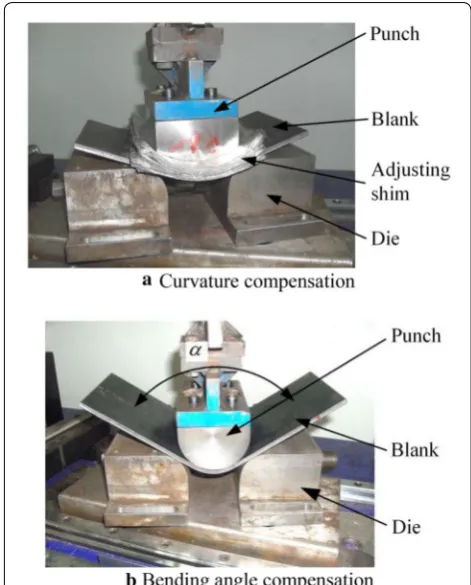
As shown in Figure 6(a), the experimental tool of cur-vature compensation control is mainly composed of punch, die and adjusting shim. The fillet radius r2 of the lower die is 25 mm, and the center distance L between the two fillets is 100 mm. There are three punches whose radius are 60 mm, 80 mm and 113.33 mm, respectively. The shims in the figure are medium-hard thin aluminum sheets with an average thickness of 0.08 mm, which are combined with the punch to form an equivalent punch, to achieve continuous changes in bending radius. The bending angle compensation control experiment and the curvature compensation experiment share a set of lower molds with a semi-circular punch with a radius of 33.33 mm, as shown in Figure 6(b).
The test sheet is A283-D steel, whose geometry and material properties are shown in Table 1. In fact, the pro-posed iterative compensation algorithm does not need the material properties, and Table 1 is only to give the material information.
The iterative compensation control experiment consists of two groups. The first group is the validation experi-ment of the curvature convergence. Using the combina-tions of punch and shims, the equivalent bending radius of 60 mm, 68 mm, 80 mm, 90 mm and 113.33 mm are obtained to bend the blank, and the curvature before and after the springback is measured to analyze its con-vergence. The second group is the iterative compensa-tion experiment of the curvature, that is, the iterative compensation algorithm proposed in Section 1 is used to obtain the target bending radius ρd of 70 mm and 95 mm with the error accuracy of ± 0.1%. In order to facilitate the measurement of the experimental data, the bending process is carried out by controlling the bending radius ρ, which is analyzed after being converted into curvature K.
Similar to the curvature, the iterative compensation control experiment of the bending angle also includes two groups. The first group is the convergence validation experiment of the bending angle. Several sets of bending experiments are carried out by controlling the stroke of Figure 6 Iterative compensation experiment of V-free bending
Table 1 Geometrical dimensions and material properties of A283‑D steel sheet Parameter Length (mm) Width (mm) Thickness
(mm) Elastic modulus (GPa) Plasticity modulus (MPa) Yield strength (MPa)
Free bending 200 120 4.9 179 1067 181
punch, and then the bending angle before and after the springback is measured to analyze the convergence. The second group is the iterative compensation experiment of the bending angle, where the target bending angle αd is 30° and 60° and the error is not more than 0.5%. In the V-free bending process, the covering angle of the punch in contact with the blank is approximated as bending angle. Therefore, according to the geometric relations, the stroke of punch S and bending angle α satisfy the relational expression:
4.2 Experimental Results and Analysis of Curvature Compensation
As shown in Figure 7, the loading and unloading experi-ments are carried out on the blanks with different bend-ing radius. The curvature of the central layer before and after springback is shown in Figure 8, which is fit-ted to obtain the relation KP=− 5.5817K2 + 1.0419K
+ 10−5. Obviously, when the curvature is greater than 0.00375 mm−1, the slope of any point on the curve is less than 1, and the larger the curvature, the smaller the slope. Therefore, it is known that the curvature can be used as (34) S=(r1+r2+t)
1−cosα2 +tanα2L
2−(r1+r2+t)·sin α 2
.
an iterative parameter to perform the springback control, which is also consistent with the theoretical analysis.
The iterative compensation process of curvature is shown in Table 2 with target bending radius of 70 mm and 95 mm, whose corresponding curvatures are 1.42857 × 10⁻² mm−1 and 1.05263 × 10⁻² mm−1. Taking
Figure 7 V-free bending process by different equivalent die
0.8 1.0 1.2 1.4 1.6 1.8
0.8 1.0 1.2 1.4 1.6
Kp=-5.5817K2+1.0419K+10-5
Curvatur
e
after springback
Kp
(1
0
-2 mm -1 )
Curvature before springback K(10-2mm-1) Experimental point
Fitted curve
the bending radius ρd of 70 mm as the example, the itera-tive control process of bending control is as follows.
Step 1: The compensation accuracy is determined to be ± 0.1%, that is, the error value of the radius or curvature are less than ± 0.07 mm or ± 1.43 × 10⁻⁵ mm−1;
Step 2: The blank is bent and unloaded for the first time by the punch with a radius of the target value; the radius of the bending piece before and after springback are ρ1= 70.021 mm and ρp1= 73.072 mm respectively; after these data are converted to curvature, the iterative error is cal-culated to be
K
1
p −Kd
= 59.940 × 10
−5 mm−1,
which does not meet the accuracy require-ments, so a second compensation is required; the curvature of the second compensation is
calculated as
Knext1 =K1+
K
1 p −Kd
= 1488.08×10
−5 mm−1;
Step 3: The second bending is carried out on the equiv-alent punch with the radius of ρnext1 =1/Knext1 = 67.200 mm by adjusting the shims; the meas-ured bending radius before and after spring-back are ρ2= 67.252 mm and ρp 2= 70.179 mm
the error is
K
2 p −Kd
= 3.644 × 10
−5 mm−1
and continue the third compensation, whose
curvature is
Knext2 =K2+
K
2
p −Kd
= 1490.59 × 10
−5 mm−1;
Step 4: Adjusting the shims to obtain an equivalent punch with a radius of ρ2next= 67.088 mm and performing the third bending; the bending radius before and after the springback are ρ3= 67.106 mm and ρp 2= 70.027 mm and the error is
K
2 p−Kd
= 0.546 × 10
−5 mm−1 which
meets the requirement of precision, so the iter-ative compensation ends.
In order to obtain a wide-plate bending piece with a radius of 70 mm, the punch radius is determined to be 67.088 mm by three iterative compensation, and the pre-cision is controlled within ± 0.1%. From Table 2, it can be seen that with the increase of the compensation times, the compensation error decreases rapidly, and the itera-tive parameter quickly approaches the target value. It is shown that the curvature can be used as an iterative parameter for the V-free bending process of the wide plate. The size of the punch can be determined with lim-ited times of iterations to obtain the bending piece satis-fying the precision.
4.3 Experimental Results and Analysis of Bending Angle Compensation
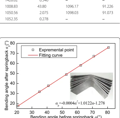
The bending angles before and after springback by con-trolling the stroke of punch are shown in Figure 9, which is consistent with αp=− 0.0004α2+ 1.0122α − 1 .278. Obviously, when the bending angle is greater than 20°, the slope of any point on the curve is less than 1.
Table 2 The iterative compensation process of curvature in V‑free bending
ρd (mm) Kd (10−5 mm−1) No. ρ (mm) ρp (mm) K (10−5 mm−1) Kp (10−5 mm−1) Kp−Kd
(10−5 mm−1) Knext (10
−5 mm−1) ρnext (mm)
70 1428.57 1 70.021 73.066 1428.14 1368.63 59.940 1488.08 67.200
2 67.252 70.179 1486.94 1424.93 3.644 1490.59 67.088
3 67.106 70.027 1490.18 1428.02 0.546 ‒ ‒
95 1052.63 1 95.023 99.124 1.05238 1008.83 43.80 1096.17 91.226
2 91.245 95.188 1.09595 1050.56 2.075 1098.03 91.073
3 91.089 95.025 1.09783 1052.35 0.278 ‒ ‒
20 30 40 50 60 70 80
20 30 40 50 60 70 80
αp=-0.0004α2+1.0122α-1.278
Bending angle after springback
αp
(°
)
Bending angle before springback α(°) Expremental point
Fitting curve
Therefore, the bending angle can be used as an iterative parameter for iterative compensation control.
The compensation process of bending angle αd of 30°
and 60° in V-free bending is shown in Table 3, which is similar to the iterative compensation experiment of curvature, and will not be repeated here. Similar to the iterative compensation procedure of curvature, the compensation error of the bending angle is reduced so quickly that the target value is obtained after 2‒3 itera-tions with an error of less than 0.5%. It is shown that the springback control method based on the iterative com-pensation algorithm has a stable convergence direction and the error can be evaluated. It is a finite compensation method with practical value.
5 Iterative Compensation Experiment of Stretch‑bending Process
5.1 Experimental Device and Program
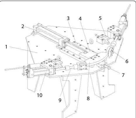
The iterative compensation experiment system of cur-vature in the bending process is mainly composed of an arm-type stretch-bending tester, a signal monitor-ing equipment and a shape measurmonitor-ing equipment, as shown in Figure 10. The arm-type test machine consists of hydraulic power pack, electric control unit and actua-tor, which is used for stretch-bending deformation of
the blank. Signal detection equipment is developed by the LabVIEW-based data acquisition system for real-time detection of tension. The measuring device is the CMM used in a V-shaped free bending experiment to measure the residual radius of stretch-bending part after springback.
The concrete structure of the actuator is shown in Fig-ure 11. The tension is provided by the stretch cylinder 10 and is taken by the tension sensor 9 and transmitted to the data acquisition system. The piston rod of the bending cylinder 2 drives the bending mould 8 fixed to the slider 4 to be linearly moved until the workpiece is bonded to the mold. The radius of the bending die is 150 mm, 220 mm and 300 mm, respectively, which are combined with the
Table 3 Experimental results of bending angle
compensation
αd (°) No. α (°) αp (°) αp−αd
(°) αnext
(°)
30 1 29.778 26.351 3.649 33.427
2 33.352 29.861 0.139 ‒
60 1 59.606 55.645 4.355 63.961
2 63.607 59.574 0.426 64.033
3 63.829 59.792 0.208 ‒
pack
Actuator Electrical control unit
a
Hydraulic powerb
c
Figure 10 Experimental system of curvature iterative compensation for stretch-bending process: a stretch-bending testing machine, b signal monitoring equipment, c CMM
1
5 4
3 2
10
6
7
8 9
shims into an equivalent mold, to achieve the fine-tun-ing of bendfine-tun-ing radius. The geometric dimensions of the A283-D steel plates are shown in Table 1.
The iterative compensation experiments of curvature in stretch-bending consists of two groups. The first group is the validation experiment of the curvature convergence. The tension is maintained at about 7200 N, so that the cross-section stress σ is slightly greater than the yield stress σs , and the blank is bent by the equivalent mold with the bending radius ρ of 150 mm, 160 mm, 220 mm, 230 mm, 300 mm and 310 mm. Then the residual curva-ture after springback is measured to analyze its conver-gence. The second group is the iterative compensation experiment of curvature to obtain the target bending radius ρd of 159 mm and 231 mm with the error accuracy of ± 0.1%.
5.2 Experimental Results and Analysis of Curvature Compensation
As shown in Figure 12, the curvature of the central layer before and after springback is fitted to obtain the relation KP=−26.798K2+ 1.0807K − 0.0005. Obviously, when the curvature is greater than 0.00301 mm−1, the slope of any point on the curve is less than 1, so the curvature can be
used as an iterative parameter to perform the springback control in stretch-bending, which is also consistent with the theoretical analysis.
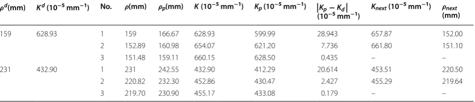
The iterative compensation process of curvature is shown in Table 4 with target bending radius of 159 mm and 231 mm, whose corresponding curvatures are 6.2893 × 10⁻³ mm−1 and 4.3290 × 10⁻³ mm−1, which is similar to the iterative compensation experiment in free-bending, and will not be repeated here. The ten-sion in the experiment is provided by the hydraulic cyl-inder, which has the fluctuation deviation of 100‒300 N. It can be seen that the compensation error of the bend-ing angle is reduced so quickly that the target value is obtained after two to three iterations with an error of less than ± 0.1%. This suggests that the iterative com-pensation algorithm can be used for curvature of the springback control in the stretch-bending process.
6 Conclusions
(1) Based on the simple iterative method, an iterative compensation algorithm for springback control in plane deformation is proposed. The new method does not depend on material properties and mechanical models, making it easier for engineer-ing applications.
(2) According to the local convergence theorem, the convergence criterion of iterative parameters is established, which provides the theoretical basis for the die surface modification in the springback con-trol problem.
(3) In the light of criterion, the iterative convergence of curvature and bending angle in V-free bending and the curvature in stretch-bending is theoretically proved.
(4) Experimental results of springback control in V-free bending and stretch-bending processes show that, the target curvature with error of less than ± 0.1% and the bending angle with error less than 0.5% can be obtained by 2‒3 iterations.
3 4 5 6 7
2 3 4 5 6 7
Kp=-26.798K2+1.0807K-0.0005
Curvat
ure af
ter springback
Kp
(1
0
-3 mm -1 )
Curvature before springback K(10-3mm-1) Expremental point
Fitting curve
Figure 12 Curvatures of bending parts in stretch-bending before and after springback
Table 4 The iterative compensation process of curvature in stretch‑bending
ρd(mm) Kd (10−5 mm−1) No. ρ(mm) ρp(mm) K (10−5 mm−1) Kp (10−5 mm−1) Kp−Kd
(10−5 mm−1) Knext (10
−5 mm−1) ρnext
(mm)
159 628.93 1 159 166.67 628.93 599.99 28.943 657.87 152.00
2 152.89 160.98 654.07 621.20 7.736 661.80 151.10
3 151.48 159.11 660.15 628.50 0.435 – –
231 432.90 1 231 242.55 432.90 412.29 20.614 453.51 220.50
2 220.82 232.30 452.86 430.47 2.427 455.29 219.64
Authors’ Contributions
RM was in charge of the whole trial; CW wrote the manuscript; RZ and JZ assisted with sampling and laboratory analyses. All authors read and approved the final manuscript.
Author Details
1 Key Laboratory of Advanced Forging, & Stamping Technology and Science,
Ministry of Education of China, Yanshan University, Qinhuangdao 066004, China. 2 College of Mechanical Engineering, Yanshan University,
Qinhuang-dao 066004, China. 3 College of Mechanical and Energy Engineering, Ningbo
Institute of Technology, Zhejiang University, Ningbo 315100, China. 4 Key
Laboratory of Roll Forming Technology Research, Ningbo 315100, Zhejiang Province, China.
Authors’ Information
Rui Ma, born in 1978, is currently a professor at Yanshan University, China. He received his PhD degree from Yanshan University, China, in 2006. His research interests include stamping forming and intelligent control.
Chunge Wang, born in 1989, is currently a lecturer at Ningbo Institute of Technology, Zhejiang University, China. She received her PhD degree from Yanshan University, China, in 2018. Her main research interests include metal superplastic forming and intelligent manufacturing.
Ruixue Zhai, born in 1984, is currently a lecturer at Yanshan University, China. He received his PhD degree from Yanshan University, China, in 2013. His research interests include metal plastic forming.
Jun Zhao, born in 1957, is currently a professor at Yanshan University, China. He received his PhD degree from Harbin Institute of Technology, China, in 1997. His research interests include stamping process and intelligent research, and precision plastic forming.
Competing Interests
The authors declare that they have no competing interests.
Funding
Supported by Hebei Provincial Natural Science Foundation of in China (Grant Nos. E2015203244, E2016203266), and Program for the Youth Top-notch Talents of Hebei Province.
Received: 25 November 2017 Accepted: 6 March 2019
References
[1] G Wei, R H Wagoner. Die design method for sheet springback. International Journal of Mechanical Sciences, 2004, 46(7): 1097-1113.
[2] R Ruffini, J Cao. Using neural network for springback minimization in a chan-nel forming process. Journal of Material Process Technology, 2010, 1: 77-85. [3] Z M Fu, J H Mo, F Han, et al. Tool path correction algorithm for single-point
incremental forming of sheet metal. International Journal of Advanced Manu-facturing Technology, 2013, 64(9): 1239-1248.
[4] J Zhao, R X Zhai, Z P Qian, et al. A study on spring back of profile plane stretch-bending in the loading method of pretension and moment. Interna-tional Journal of Mechanical Sciences, 2013, 75: 45-54.
[5] Z W Gu, M W Lv, X Li, et al. Stretch bending defects control of L-section aluminum components with variable curvatures. International Journal of Advanced Manufacturing Technology, 2016, 85(5): 1053-1061.
[6] R X Zhai, X H Ding, S M Yu, et al. Stretch bending and springback of profile in the loading method of prebending and tension. International Journal of Mechanical Sciences, 2018, 144: 746-764.
[7] R K Verma, K Chung, T Kuwabara. Effect of pre-strain on anisotropic harden-ing and sprharden-ingback behavior of an ultra low carbon automotive steel. ISIJ International, 2011, 51(3): 482-490.
[8] B Chongthairungruang, V Uthaisangsuk, S Suranuntchai, et al. Experimental and numerical investigation of springback effect for advanced high strength dual phase steel. Material Design, 2012, 39: 318-328.
[9] L F Wang, G H Huang, H Zhang, et al. Evolution of springback and neutral layer of AZ31B magnesium alloy V-bending under warm forming conditions. Journal of Material Process Technology, 2013, 213(6): 844-850.
[10] Y Y Zong, P Liu, B Guo, et al. Springback evaluation in hot v-bending of Ti-6Al-4V alloy sheets. International Journal of Advanced Manufacturing Technology, 2015, 76(1): 577-585.
[11] W L Edwards, T J Grimm, I Ragai, et al. Optimum process parameters for springback reduction of single point incrementally formed polycarbonate. Procedia Manufacturing, 2017, 10: 329-338.
[12] A P Karafillis, M C Boyce. Tooling design in sheet metal forming using spring-back calculations. International Journal of Mechanical Sciences, 1992, 34(2): 113-131.
[13] A P Karafillis, M C Boyce. Tooling and binder design for sheet metal forming processes compensating springback error. International Journal of Machine Tools & Manufacture, 1996, 36(4): 503-526.
[14] R Lingbeek, J Huetink, S Ohnimus, et al. The development of a finite elements based on springback compensation tool for sheet metal products. Journal of Material Process Technology, 2005, 169(1): 115-125.
[15] H S Cheng, J Cao. An accelerated springback compensation method. Interna-tional Journal of Mechanical Sciences, 2007, 49(3): 267-279.
[16] X A Yang, F Ruan. A die design method for springback compensation based on displacement adjustment. International Journal of Mechanical Sciences, 2011, 53(5): 399-406.
[17] G Cafuta, N Mole, B Štok. An enhanced displacement adjustment method: springback and thinning compensation. Material Design, 2012, 40: 476-487. [18] W A Siswanto, A D Anggono, B Omar, et al. An alternate method to spring-back compensation for sheet metal forming. The Scientific World Journal, 2014: 301271.
[19] J Liao, X Xue, C Zhou, et al. A springback compensation strategy and applica-tions to bending cases. Steel Research International, 2013, 84(5): 463–472. [20] Z K Zhang, J J Wu, S Zhang, et al. A new iterative method for springback
control based on theory analysis and displacement adjustment. International Journal of Mechanical Sciences, 2015, 105: 330-339.
[21] I N Vladimirov, M P Pietryga, S Reese. Prediction of springback in sheet forming by a new finite strain model with nonlinear kinematic and isotropic hardening. Journal of Material Process Technology, 2009, 209(8): 4062-4075. [22] X Q Peng, S Q Shi, K K Hu. Comparison of material models for spring back prediction in an automotive panel using finite element method. Journal of Materials Engineering and Performance, 2013, 22(10): 2990-2996.
[23] A Maia, E Ferreira, M C Oliveira, et al. 3-Numerical optimization strategies for springback compensation in sheet metal forming. Computational Methods & Production Engineering, 2017: 51-82.
[24] I Gil, E Mugarra, J Agirre, et al. Influence of material and tribological model-ling on the prediction of big size automotive components springback. Key Engineering Materials, 2016, 716: 713-718.
[25] F M Brandão, S Delijaicov, Bortolussi R. CAF—a simplified approach to calculate springback in Al 7050 alloys. International Journal of Advanced Manufacturing Technology, 2017, 91(9): 1-12.
[26] [26]D M Neto, M C Oliveira, A D Santos, et al. Influence of boundary condi-tions on the prediction of springback and wrinkling in sheet metal forming. International Journal of Mechanical Sciences, 2017, 122: 244-254.
[27] G Y Gao, G C Yu, J Zhao, et al. Rolling round process of four-roll and its spring-back analysis. Journal of Plasticity Engineering, 2017, 24(1): 55-62.
[28] N Saito, M Fukahori, D Hisano, et al. Effect of stress relaxation on springback of steel sheet in warm forming. Key Engineering Materials, 2017, 725: 671-676. [29] C G Wang, G C Yu, W Wang, et al. Deflection detection and curve fitting in
three-roll continuous straightening process for LSAW pipes. Journal of Materi-als Processing Technology, 2018, 255: 150-160.
[30] Y X Wang. Forging and stamping technology. Beijing: Metallurgical Industry Press, 1994.
[31] Y B Zhong. Stamping process and die design. BeijJing: Machinery Industry Press, 2000.