ORIGINAL ARTICLE
Dynamic Characteristics Analysis
with Multi-Directional Coupling in a TBM
Mainframe
Laikuang Lin
1,2, Yimin Xia
1,2*, Zhengguang Li
1, Caizhang Wu
1, Yongliang Cheng
1,3and Qing Tan
1,2Abstract
The cutterhead of a full-face rock tunnel boring machine (TBM) is constantly subjected to varying impact and dynamic loads during tunneling processes, resulting in relatively large vibrations that could easily lead to fatigue cracking of the entire machine and affect the tunneling performance and efficiency. To explore the dynamic char-acteristics of the TBM mainframe, a TBM from a water-diversion project is investigated in this research. According to the TBM vibration transmission route, an equivalent dynamic model of the TBM mainframe is established using the lumped-mass method in which the relevant dynamic parameters are solved. Additionally, the dynamic response characteristics of the TBM mainframe are analyzed. The results indicate that the vibration levels in three directions are approximately the same, the multi-directional vibration of the cutterhead is more intense than that of other compo-nents, and the vibration and external excitation exhibit identical change trends. A set of vibration field tests is per-formed to analyze the in situ dynamic responses of the mainframe and verify the correctness of the dynamic model. The theoretical and measured acceleration values of the TBM mainframe have the same magnitude, which proves the validity of the dynamic model and its solution. The aforementioned results provide an important theoretical value and practical significance for the design and assessment of the TBM mainframe.
Keywords: Tunnel boring machine, Time-varying excitation, Dynamic model, Load transfer, Dynamic response
© The Author(s) 2019. This article is distributed under the terms of the Creative Commons Attribution 4.0 International License (http://creat iveco mmons .org/licen ses/by/4.0/), which permits unrestricted use, distribution, and reproduction in any medium, provided you give appropriate credit to the original author(s) and the source, provide a link to the Creative Commons license, and indicate if changes were made.
1 Introduction
The tunnel boring machine (TBM) is large-scale under-ground equipment that is widely used in underunder-ground tunnel projects owing to high safety and reliability, low manpower requirement, minor environmental damages, and rapid excavation speed [1, 2]. As a key component of the TBM, the mainframe is composed of a cutterhead system, main drive system, shield, and main girder as well as a supporting-thrust system. Because of complicated geological conditions and variable tunneling parameters, a tunnel often features high strength and high confining pressure as well as a high quartz content, along with the step crushing of rocks. In the tunneling process, the TBM cutterhead is subjected to large thrust and torque caused
by the interaction between the cutters and rock [3, 4], which may result in significant damages, such as cracking of the cutterhead and loosening or separation of bolts, and affect the fatigue life of the TBM mainframe.
Studies on the TBM mainframe system have been car-ried out by several researchers, including those on external loads, thrust, torque, overturning torque, and unbalanced radial force in the tunneling process. Relevant models have also been established to conduct dynamic characteristic analyses of the cutterhead system. Rostami [5] analyzed various factors affecting the rock-breaking load of a disc cutter, established the CSM (Colorado School of Mines) force-estimation model for the cutter, and evaluated the performance of the cutterhead from the perspective of disc cutter layouts. Xia et al. [6] studied the formation mecha-nism and change pattern of the side force suffered by the center cutter and set up a calculation model for predict-ing the average side force. Huo et al. [7] subdivided the TBM disc cutter into center, inner, and gauge cutters and
Open Access
*Correspondence: [email protected]
1 College of Mechanical and Electrical Engineering, Central South
University, Changsha 410083, China
presented a multi-stage rock fragmentation load predic-tion model for disc cutter groups based on the dense-core theory and types of disc cutters. Shi et al. [8] put forward a method for calculating the cutterhead torque by tak-ing into account the cutterhead structure, cutttak-ing princi-ple, and geological conditions. Additionally, Zhou et al. [9] and Geng et al. [10] studied the factors that influence the thrust and torque of cutterheads and derived a model for calculating the relevant thrust, torque, overturning torque, and other external loads. Xia et al. [11] modified the cutterhead overturning moment calculation model and analyzed the mechanical performance of a typical TBM cutterhead under different working conditions. Zhao et al. [12] analyzed the composition of earth pressure balance (EPB) TBM cutterhead torque and developed a theoretical TBM torque model for a rock–soil interface mixed ground. Because of the difficulties in obtaining the accurate load of the cutterhead using theoretical analysis, test methods have been applied to acquire the load data of the cutterhead and its change trends. A test of external loads was performed by Entacher et al. [13, 14], who presented a method to detect the three-directional loading of a disc cutter in real-time and conducted a field test in the Austrian Koralm Tun-nel. Geng et al. [15] proposed an experimental method to investigate the rock-cutting process of a TBM gauge cut-ter. According to the theoretical models, Zhang et al. [16, 17] analyzed the total load in an EPB TBM tunneling pro-cess and established a predictive model for the total load, which reflected the influence of the geological, operating, and structural parameters. Sun et al. [18, 19] and Li et al. [20] established a coupling nonlinear dynamic model of a cutterhead system to analyze the dynamic characteristics of the cutterhead. Huo et al. [21, 22] established multi-degree-of-freedom coupling dynamic models for the disc cutter and cutter system and revealed the dynamic characteris-tics of the disc cutter and cutter system. In addition, Huo et al. [23, 24] presented multi-coupling dynamic models for the TBM main drive and supporting systems and carried out a field strain test to verify the models. Festa et al. [25] set up a kinematic model for a TBM based on theoretical and geometrical considerations, and the ground displace-ments were obtained through the model and verified using the TBM monitoring data. In addition, considering the redundant driven rotary system, propulsion system, and geological conditions, Zhang et al. [26] and Huang et al. [27] established a mutual coupling dynamic model for cut-terhead tunneling to analyze the dynamic characteristics of the rotary and supporting-propulsion systems under com-plex geological conditions.
As mentioned before, efforts have been intensified in the research and design of TBM cutterheads. However, profound studies on the TBM mainframe from the per-spective of dynamics have not yet been performed. The
existing dynamic model has been simplified to merely analyze the data of the main drive without consider-ing the supportconsider-ing or propellconsider-ing forces provided by the main girder and gripper shoes in the mainframe. As a result, the transmission path is not closed. Additionally, differences in the frequency spectrum characteristics exist between the simulation-predicted dynamic and real external loads. Therefore, to investigate the dynamic characteristics of the TBM mainframe, a dynamic model of a TBM mainframe is established, which comprehen-sively considers the time-varying external excitations, transmission route of the vibration, and three-dimen-sional forces obtained from rock-breaking experiments. In addition, a set of field tests is carried out to collect field data and validate the correctness of the dynamic model. The present study provides a theoretical basis for evaluat-ing and designevaluat-ing the TBM mainframe structure that can effectively prevent cracking, reduce the vibrations of the TBM mainframe, and prolong the fatigue life of the main bearing as well as improve tunneling efficiency.
2 Dynamic Model of TBM Mainframe
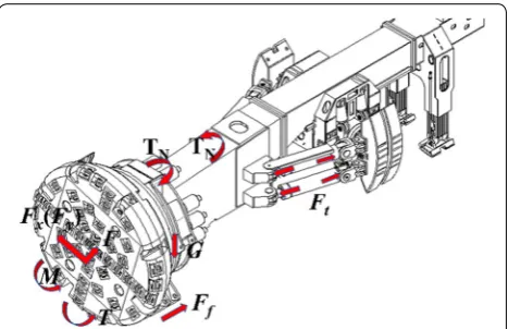
During the tunneling process, the vibrations of the TBM mainframe consist of lateral, vertical, tunneling, lateral overturning, and vertical overturning vibra-tions. The loads acting on the mainframe are shown in Figure 1, where Fz and T are the thrust force in the
tunneling direction and total torque, respectively, and
M, Fx, and Fy represent the overturning moment,
lat-eral unbalanced force, and vertical unbalanced force, respectively. Total thrust Ft is provided by the
propel-ling hydraulic cylinders to move the TBM forward. The cutterhead, main drive, and first section of the main girder are mainly backed by the bottom shield, which are tightly attached to the rock, thus bearing the fric-tion resistance force Ff caused by gravity G.
The transmission path of the mainframe external excitations and vibrations is opposite that of the TBM
tunneling thrust. The three-directional impact loads of the cutterhead are created by the disc cutters that break the rock during TBM tunneling. Through a connection flange in the cutterhead, the load and vibration are trans-mitted from the cutterhead to the main bearing and sub-sequently to the other parts behind the main drive. Then, through the main girder and propelling hydraulic cylin-ders at both sides of the main girder, the load and vibra-tion are transmitted to the saddle holder of the gripper shoes that grip the rock, providing a forward reaction force and reducing the vibration of the gripper shoes.
According to the analysis of the load transmission path in the TBM mainframe, the lumped-mass method is adopted to simplify the connection relationships of each component to the spring-damping system to establish
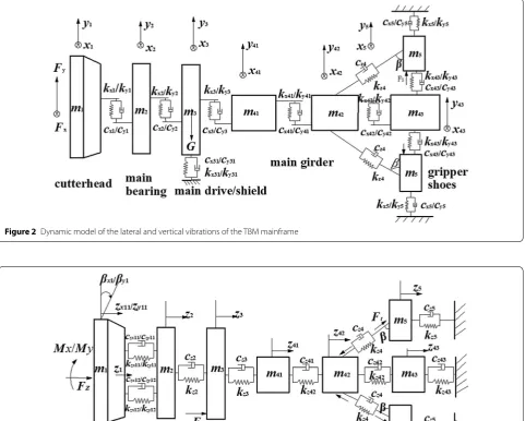
an equivalent dynamic model of the TBM mainframe, as shown in Figures 2 and 3.
Figure 2 shows a dynamic model of the lateral and verti-cal vibrations of the mainframe. Figure 3 shows a dynamic model that represents the coupling relationship between the tunneling and overturning vibrations in the mainframe. When the overturning vibration is calculated, the connec-tion relaconnec-tionships between the cutterhead and the main bearing are simplified into four spring-damping systems. The whole overturning stiffness of the cutterhead is equal to the tunneling joint stiffness. In the dynamic model, x, y, and z denote the lateral, vertical, and tunneling directions, respectively. m1, m2, m3, m41, m42, m43, and m5 represent the masses of the cutterhead, main bearing, main drive (including the shield), main girder 1, main girder 2, main
Figure 2 Dynamic model of the lateral and vertical vibrations of the TBM mainframe
girder 3, and gripper shoes, respectively. x1, x2, x3, x41, x42,
x43, and x5 represent the lateral degrees of freedom of the cutterhead, main bearing, main drive, main girder 1, main girder 2, main girder 3, and gripper shoes respectively. y,
z, and θ denote the corresponding vertical, tunneling, and overturning degrees of freedom respectively. kx1, kx2, kx3,
kx41, kx42, kx43, kx5, ky1, ky2, ky3, ky41, ky42, ky43, and ky5 denote the lateral and vertical equivalent stiffness values of the cutterhead, main bearing, main drive, main girder 1, main girder 2, main girder 3, and gripper shoes, whereas c repre-sents the corresponding damping.
According to the dynamic model, the dynamic equations of the vibration transmission in the TBM mainframe under different degrees of freedom are presented. The lateral and vertical degrees of freedom are expressed as follows:
The tunneling degree of freedom is expressed as follows:
The overturning degree of freedom is expressed as follows: (1)
m1· ¨x1+cx1(x˙1− ˙x2)+kx1(x1−x2)=Fx, m1· ¨y1+cy1
�
˙
y1− ˙y2
�
+ky1� y1−y2
�
=Fy,
m2· ¨x2+cx1(x˙2− ˙x1)+cx2(x˙2− ˙x3)+kx1(x2−x1)+kx2(x2−x3)=0,
m2· ¨y2+cy1
�
˙
y2− ˙y1
�
+cy2�
˙
y2− ˙y3
�
+ky1� y2−y1
�
+ky2� y2−y3
�
=0,
m3· ¨x3+cx2(x˙3− ˙x2)+cx3(x˙3− ˙x41)+cx31· ˙x3+kx2(x3−x2)+kx3(x3−x41)=0,
m3· ¨y3+cy2
�
˙
y3− ˙y2
�
+cy3�
˙
y3− ˙y41
�
+cy31· ˙x3+ky2� y3−y2
�
+ky3� y3−y41
�
=0,
m41· ¨x41+cx3(x˙41− ˙x3)+cx41(x˙41− ˙x42)+kx3(x41−x3)+kx41(x41−x42)=0,
m41· ¨y41+cy3
�
˙
y41− ˙y3
�
+cy41�
˙
y41− ˙y42
�
+ky3� y41−y3
�
+ky41�
y41−y42
�
=0,
m42· ¨x42+cx41(x˙42− ˙x41)+cx42(x˙42− ˙x43)+2cz4(x˙42− ˙x5)
+kx41(x42−x41)+kx42(x42−x43)+2kz4(x42−x5)=0,
m42· ¨y42+cy41�y˙42− ˙y41�+cy42�y˙42− ˙y43�+ky41�y42−y41�+ky42�y42−y3�=0,
m43· ¨x43+cx42(x˙43− ˙x42)+2cx43(x˙43− ˙x5)+kx42(x43−x42)+2kx43(x43−x5)=0,
m43· ¨y43+cy42
�
˙
y43− ˙y42
�
+2cy43�
˙
y43− ˙y5
�
+ky42�
y43−y42
�
+2ky43� y43−y5
�
=0,
m5· ¨x5+cx43(x˙5− ˙x43)+cz4(x˙5− ˙x42)+cx5· ˙x5
+kx43(x5−x43)+kz4(x5−x42)+kx5·x5−F5=0,
m5· ¨y5+cy43
�
˙
y5− ˙y43
�
+cy5· ˙y5+ky43� y5−y43
�
+ky5·y5−F5=0.
(2)
m1· ¨z1+czx11(z˙x11− ˙z2)+czx12(z˙x12− ˙z2)+czy11
�
˙
zy11− ˙z2
�
+czy12�
˙
zy12− ˙z2
�
+kzx11(zx11−z2)+kzx12(zx12−z2)+kzy11�zy11−z2
�
+kzy12�
zy12−z2
�
=Fz,
m2· ¨z2+czx11(z˙2− ˙zx11)+czx12(z˙2− ˙zx12)+czy11
�
˙
z2− ˙zy11
�
+czy12
�
˙
z2− ˙zy12
�
+cz2(z˙2− ˙z3)
+kzx11(z2−zx11)+kzx12(z2−zx12)+kzy11�
z2−zy11
�
+kzy12�
z2−zy12
�
+kz2(z2−z3)= 0,
m3· ¨z3+cz2(z˙3− ˙z2)+cz3(z˙3− ˙z41)+kz2(z3−z2)+kz3(z3−z41)=Ff,
m41· ¨z41+cz3(z˙41− ˙z3)+cz41(z˙41− ˙z42)+kz3(z41−z3)+kz41(z41−z42)=0,
m42· ¨z42+cz41(z˙42− ˙z41)+cz42(z˙42− ˙z43)+2cz4(z˙42− ˙z5)
+kz41(z42−z41)+kz42(z42−z43)+2kz4(z42−z5)= −2Ft,
m43· ¨z43+cz42(z˙43− ˙z42)+cz43· ˙z43+kz42(z43−z42)+kz43·z43=0,
m5· ¨z5+cz4(z˙5− ˙z42)+cz5· ˙z5+kz4(z5−z42)+kz5·z5=Ft.
(3)
I1x· ¨θx1−czx11(z˙x11− ˙z2)·aL+czx12(z˙x12− ˙z2)·aL −kzx11(zx11−z2)·aL+kzx12(zx12−z2)·aL=Mx, I1y· ¨θy1−czy11�z˙y11− ˙z2�·aL+czy12�z˙y12− ˙z2�·aL
−kzy11�zy11−z2�·aL+kzy12�zy12−z2�·aL=My,
where I1x and I1y are the lateral and vertical moments of
inertia, respectively. kzx11, kzx12, kzy11, and kzy12 are the tunneling equivalent stiffness values of the four pieces of cutterhead.
Coupling relationships exist between the tunneling and overturning vibrations. The relationships between the displacement of each cutterhead pieces and that of the cutterhead tunneling vibration are expressed in Eq. (4):
where zx11, zx12, zy11, and zy12 are the displacements of each cutterhead piece, z1 is the axial vibration displace-ment of the cutterhead, θx1 and θy1 are the overturn-ing angles of the cutterhead, and aL is the radius of the
cutterhead. (4)
By creating a simultaneous equation from Eqs. (2)– (4), the coupling dynamic model of the tunneling and overturning vibrations can be expressed as Eq. (5):
The above vibration transmission equations can be expressed into matrix form as:
where X is the displacement vector, M is the mass matrix, K is the stiffness matrix, C is the damping matrix, and F
is the external excitation.
3 Solution for Dynamic Parameters
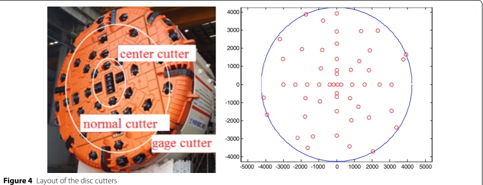
By considering the TBM used in a water-diversion pro-ject as a research obpro-ject, the layout of the disc cutters in the cutterhead is shown in Figure 4. The cutterhead
(5)
m1· ¨z1+czx11
� ˙
z1− ˙z2−aLθ˙x1
�
+czx12� ˙
z1− ˙z2+aLθ˙x1
�
+czy11� ˙
z1− ˙z2−aLθ˙y1
�
+czy12� ˙
z1− ˙z2+aLθ˙y1
�
+kzx11(z1−z2−aLθx1)+kzx12(z1−z2+θx1)
+kzy11�
z1−z2−aLθy1
�
+kzy12�
z1−z2+aLθy1
� =Fz, m2· ¨z2+czx11
� ˙
z2− ˙z1+aLθ˙x1
�
+czx12� ˙
z2− ˙z1−aLθ˙x1
�
+czy11� ˙
z2− ˙z1+aLθ˙y1
�
+czy12�˙
z2− ˙z1−aLθ˙y1�+cz2(z˙2− ˙z3)+kzx11(z2−z1+aLθx1)
+kzx12(z2−z1−aLθx1)+kzy11�
z2−z1+aLθy1
�
+kzy12�
z2−z1−aLθy1
�
+kz2(z2−z3)=0,
m3· ¨z3+cz2(z˙3− ˙z2)+cz3(z˙3− ˙z41)+kz2(z3−z2)+kz3(z3−z41)=Ff,
m41· ¨z41+cz3(z˙41− ˙z3)+cz41(z˙41− ˙z42)+kz3(z41−z3)+kz41(z41−z42)=0,
m42· ¨z42+cz41(z˙42− ˙z41)+cz42(z˙42− ˙z43)+2cz4(z˙42− ˙z5)
+kz41(z42−z41)+kz42(z42−z43)+2kz4(z42−z5)=0, m43· ¨z43+cz42(z˙43− ˙z42)+cz43· ˙z43+kz42(z43−z42)+kz43·z43=0,
m5· ¨z5+cz4(z˙5− ˙z42)+cz5· ˙z5+kz4(z5−z42)+kz5·z5=0,
I1x�aL· ¨θx1−czx11
� ˙
z1− ˙z2−aLθ˙x1
�
+czx12� ˙
z1− ˙z2+aLθ˙x1
�
−kzx11(z1−z2−aLθx1)+kzx12(z1−z2+aLθx1)=Mx �
aL,
I1y �
aL· ¨θy1−czy11
� ˙
z1− ˙z2−aLθ˙y1
�
+czy12� ˙
z1− ˙z2+aLθ˙y1
�
−kzy11�
z1−z2−aLθy1
�
+kzy12�
z1−z2+aLθy1
� =My�
aL.
(6) MX¨ +CX˙ +K =F,
diameter is 7930 mm with 51 cutters, including 8 center, 32 normal, and 11 gauge cutters. The spacing between the center cutters is 101.5 mm and that between the
nor-mal cutters is 83 mm. The inclination angles of the gauge cutters are 65.5°, 68.5°, and 70°.
3.1 External Excitations of the TBM Cutterhead
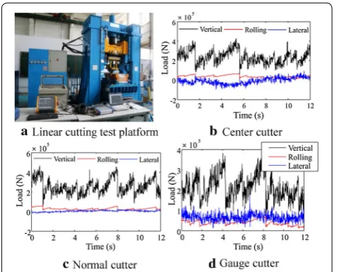
The dominant geological formation in the water-diver-sion project is granite with high compressive strength. Thus, the TBM cutterhead suffers from violent vibrations during the tunneling process. To provide loads for the cutterhead, full-scale rock-breaking tests are performed on a linear cutting machine (LCM) in Central South Uni-versity [28]. The LCM consists of the frame, moving unit, disc cutter, cutter housing unit, hydraulic unit, control
-5000 -4000 -3000 -2 -4000 -3000 -2000 -1000 0 1000 2000 3000 4000
000 -1000 0 1000 2000 30000 4000 5000
unit, and data acquisition unit, as shown in Figure 5. A 17-in disc cutter is used for the test, and rock samples with dimensions of 900 mm × 380 mm × 280 mm are used for cutter breaking. The type and mechanical prop-erties of the experimental rock are based on typical TBM geological conditions. By filtering the test data and com-bining them with simulation, three-dimensional forces can be obtained, as shown in Figure 5. The average verti-cal and rolling forces in the center cutter are 236 and 34.7 kN, respectively, and the lateral force is concentrated in the range from − 80 to 80 kN. The average vertical and rolling forces of the normal cutter are 256 and 29.1 kN, where the lateral force ranges from − 20 to 20 kN. The average vertical and rolling forces of the gauge cutter are 214 and 35.74 kN, respectively. The lateral force ranges from 20 to 120 kN.
Based on the radius, position angle, and tilt angle of the cutter as well as the cutter loads in three direc-tions, the total thrust, total torque and change trend of the radial unbalanced force of the cutterhead can be obtained, which can be presented as time-varying exter-nal excitations.
3.2 Calculation of Equivalent Stiffness and Damping
Three-row rollers are used in the TBM main bearing, as shown in Figure 6, i.e., main axial rollers that withstand the thrust load, secondary axial roller bearing for the bending moment, and radial rollers that carry the radial load.
The elastic deformation in the elastic line-contact area can be calculated using an empirical equation [29]. The
Hertz contact stiffness between the axial roller and raceway is defined as
where Lwe represents the effective length of the rollers
and Q denotes the contact load.
According to the equation that calculates the oil-film thickness of the contact area, the contact stiffness in the contact area can be expressed as
where α is the viscosity pressure coefficient of the lubri-cant, η0 is the dynamic viscosity of the lubricant, u is the average speed, R is the equivalent curvature radius of the contact area, E is the elastic modulus, and E0 is the equiv-alent elastic modulus.
The contact-area stiffness can be calculated as follows:
where kH denotes the Hertz contact stiffness and kL
denotes the contact stiffness of the oil film.
According to the elastic fluid dynamics, the contact damping between the rollers and roller raceway consists of the roller structural and oil-film damping. Considering the effect of the oil-film thickness, the main-bearing damping coefficient is calculated using the following equation [30].
The damping between the rollers and inner raceway can be expressed as:
(7)
kH′ = dQ
dδ
=2.894×10⁵L0.8weQ0.1,
(8) kL= dQ
dhc
= −2.18×10³ E 0.03 0 Q1.13 α0.54(η
0u)0.7R0.43L0.13we ,
(9)
k= 1
1kH+1
kL ,
(10) c1=
27.4R1.5·L0.805we ·Z0.805·Q0.195
α0.81η0.050 n1.05i r0.645(R
1+r)1.05(1−γ )1.695(1+γ )1.05E0−0.045
. Figure 5 Three-dimensional loads of the cutters
The damping between the rollers and surface raceway can be expressed as:
where Z is the number of rollers, ni is the rotating speed
of the raceway, r is the radius of the roller, and R1 is the radius of the inner raceway.
Employing theoretical calculations or experimental measurements to acquire the equivalent stiffness and damping parameters of the cutterhead, main drive, main girder, and support saddle of the gripper shoes is diffi-cult. Therefore, the finite-element method and empiri-cal formula are employed to obtain their stiffness and damping coefficients. The equivalent stiffness of the com-ponents can be calculated using Hooke’s law. The equiva-lent damping calculation equation can be expressed as follows:
where c is the structural damping, ζ is the damping ratio, and me and ke represent the equivalent mass and
equiva-lent stiffness, respectively.
By summarizing the aforementioned results, the stiff-ness and damping parameters of each component are obtained, and the partial parameters are listed in Table 1.
4 Dynamic Responses of TBM Mainframe
Because the vertical vibration response is similar to the lateral vibration response, this study only analyzes the vibration responses in the lateral, tunneling, and over-turning directions of the cutterhead and main girder 1.
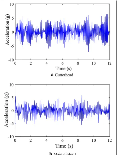
4.1 Vibration Response in Tunneling Direction
Under the impact of external excitations, the vibra-tion acceleravibra-tion curves of the TBM mainframe in the
(11) c2= 27.4R
1.5·L0.805
we ·Z0.805·Q0.195
α0.81η0.05
0 n1.05i r0.645(R1+r)1.05(1+γ )1.695(1−γ )1.05E0−0.045 ,
(12)
c= 1
1c1+1
c2 ,
(13)
c=2ξ·me·ke,
tunneling direction are shown in Figure 7. The cutterhead acceleration is concentrated from − 3.5g to + 3.5g with
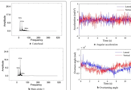
maximum acceleration of more than 7g, demonstrating an intense vibration. When the vibration is transmitted to main girder 1, the acceleration changes to the range from − 2.8g to 2.8g with a peak of 5.9g. The frequency responses of the TBM mainframe in the tunneling direc-tion are shown in Figure 8. The vibration energy of the
Table 1 Partial stiffness and damping parameters of mainframe
Cutterhead Main drive Main girder 1 Gripper shoes
Lateral stiffness (N m) 1.15 × 10¹⁰ 5 × 10⁹ 6.38 × 10⁸ 8.68 × 10¹⁰
Overturning stiffness (N m) 1.56 × 10¹¹ 6.16 × 10¹⁰ 5.7 × 10⁹ 2.11 × 10¹¹
Tunneling stiffness (N m) 4.72 × 10¹⁰ 2.5 × 10⁹ 1.8 × 10¹⁰ 3.36 × 10¹⁰
Lateral damping (N s/m) 1.75 × 10⁶ 1.04 × 10⁶ 1.47 × 10⁵ 1.84 × 10⁶
Lateral damping (N s/m) 3.55 × 10⁶ 7.35 × 10⁵ 7.9 × 10⁵ 1.14 × 10⁶
cutterhead is mainly in the frequency range of 0–130 Hz, and the vibration energy of the main girder is mainly concentrated in the frequency range of 0–70 Hz.
4.2 Vibration Responses in Overturning Direction
The vibration angular acceleration of the cutterhead in the overturning direction is shown in Figure 9a, and the overturning angle curve is shown in Figure 9b. The overturning angular acceleration is relatively small, which mainly ranges from − 1.5 to + 1.5 rad/s2 with the cutterhead rotation. Overall variation periods of angu-lar acceleration and overturning angle are equal to the period of cutterhead rotation. Frequency responses of the mainframe in the overturning direction are shown in Figure 10. The vibration energy occurs mainly in the fre-quency range of 0–130 Hz.
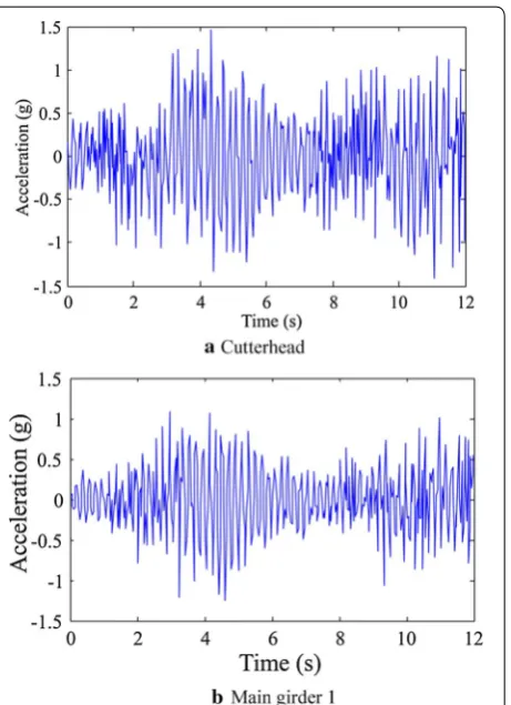
4.3 Vibration Responses in Lateral Direction
The lateral acceleration of the cutterhead is shown in Fig-ure 11, which mainly ranges from − 1.4g to + 1.4g with a maximum of more than 1.45g. The acceleration of the main girder is slightly lower than that of the cutterhead, which can be attributed to the restraint effect of the bot-tom support shield. The acceleration of the main girder
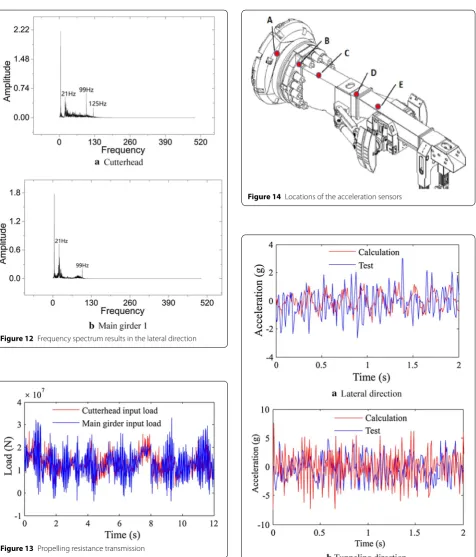
ranges from − 1.0g to + 1.0g with a maximum of 1.25g. The frequency spectrum of the lateral vibration is shown in Figure 12. Vibration energy of the cutterhead is distrib-uted in the frequency range of 0–130 Hz, whereas that of the main girder is distributed in the range of 0–100 Hz.
4.4 Transfer Law of Loads
The change trend of the propelling resistance transferred from the cutterhead to main girder 1 can be estimated from Figure 13, which clearly shows that the change trends in the transfer process are basically the same. The propelling resistance of the cutterhead is concentrated between 4200 and 22000 kN with an average value of 12848 kN. The propelling resistance of the main girder mainly ranges from 2000 to 28000 kN with an average of 12867 kN.
the vibration frequencies. The vibrations in the tunneling direction are more intense than those in the lateral direc-tion. In the load-transfer process, the mean loads remain the same, whereas the change range of the loads expands.
5 Validation of Dynamic Model Based on Field Tests
To verify the correctness of the dynamic model, a field test was performed in the TBM mainframe from a water-diversion project. The vibration tests were conducted using an acceleration test system. The locations of the acceleration test points are shown in Figure 14.
Considering the poor working condition of the cut-terhead, acceleration sensors were attached to the man-hole of the cutterhead, i.e., point A in Figure 14. The test points in the main drive were located around the B point on the main girder connecting plate, and the test points for the main girder were located on the C, D, and E point positions. The vibration signals in the manhole were transferred in a wireless manner, whereas those of the other test points were directly obtained through the transmission lines. At each test point, three acceleration sensors for the lateral, vertical, and tunneling directions were installed.
5.1 Vibration Test of Cutterhead
The field-test values of the vibration of the cutterhead are compared with the theoretical values, as shown in Figure 15. The measured values of the cutterhead lat-eral acceleration are larger than those calculated by the model, which mainly range from − 2g to + 2g. The mean-square deviation of the lateral-test acceleration is 1.01g, whereas the calculated value is 0.61g. The measured val-ues of the vibration acceleration in the tunneling direc-tion are lower than the calculated values, which mainly range from − 3g to + 3g. The mean-square deviation of the measured tunneling acceleration is 1.92g, and that of the calculated acceleration is 2.1g.
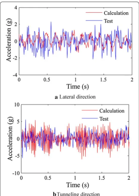
5.2 Vibration Test of Main Girder
The measured and calculated acceleration values of the main girder are shown in Figure 16, which shows that the measured values of the lateral-vibration accel-eration in the main girder are larger than the calculated values, mainly ranging from − 2g to + 2g. The mean-square deviation of the lateral measured acceleration is 0.86g, and that of the calculated value is 0.52g. In the tunneling direction, the test values of the vibration Figure 10 Frequency spectrum results in the overturning direction
acceleration are lower than the calculated values, which mainly range between − 2.3g and 2.3g with the
maxi-mum value reaching 5g. Mean-square deviation of the measured tunneling acceleration is 1.51g, and that of the calculated acceleration is 1.72g.
Comparison of the field-test and calculated values of the acceleration in the TBM mainframe reveals that the calculated values of the lateral and vertical vibration Figure 12 Frequency spectrum results in the lateral direction
Figure 13 Propelling resistance transmission
Figure 14 Locations of the acceleration sensors
acceleration are lower than the test values, whereas the calculated values of the vibration acceleration in the tun-neling direction is larger than the measured values. The reasons for the differences in the tunneling and other directions can be attributed to the complex internal structure of each component in the mainframe and the slant stiffened plate of the cutterhead. In the transmission process, partial vibrations in the tunneling direction can be transmuted into other vibrations such as the lateral and vertical vibrations due to the slant stiffened plate and complex internal structure of the mainframe.
The calculated and measured acceleration values of the TBM mainframe have the same magnitude within a relatively acceptable error range. The major error comes from the simplification of the complex internal structure of the TBM mainframe coupled with errors in the calcu-lations of the equivalent stiffness and damping.
6 Conclusions
In this study, a dynamic model that includes the cutterhead, main drive, main girder, and support-thrust system is established. The dynamic response
characteristics of the TBM mainframe and the trans-fer trend of loads are investigated both theoretically and by field tests. The main results are summarized as follows.
(1) In the tunneling process, the lateral, vertical, and tunneling vibrations of the TBM mainframe have the same vibration level in which the changes are similar to those of the external excitations.
(2) Parallel conditions exist between the vibration responses of the cutterhead and main girder. The multi-directional vibration of the cutterhead is more intense than that of the main drive, main bearing, and main girder. The vibrations in the tun-neling direction are more intense than those in the lateral direction. The frequencies of the cutterhead vibration energy are predominantly concentrated at approximately 0–130 Hz, and those of the main girder vibration energy are mainly concentrated at approximately 0–100 Hz. As the distance from the cutterhead increases, the vibration energy is con-centrated in a lower frequency. During the design of the TBM mainframe, measurement of the vibration reduction needs to be considered to prevent fatigue damage and breakdown of the cutterhead and dam-age to the main bearing.
(3) In the process of mainframe load transfer from the tunneling direction, the average load and change trend of the loads remain constant, whereas the range of the loads expands by 1.4 times with the increase in the load amplitude. As a result, when the strength of the components in the back end of the mainframe is designed and checked, the exter-nal loads from the cutterhead need to be amplified. (4) The lateral measured acceleration of the TBM
mainframe is concentrated in the range from − 2g to + 2g, and the measured acceleration in the tun-neling direction is mainly concentrated in the range from − 3g to + 3g. Comparison of the theoretical values with the actual test values from three direc-tions in the mainframe reveals that the measured and calculated vibrations are basically the same within a relatively acceptable range of error. The results have verified the correctness of the modeling and the solution of the dynamic model, which con-firm the weakest components of TBM mainframe and provide a theoretical basis for the design and evaluation of the mainframe as well as the external loads for mainframe fatigue-life analysis.
Authors’ Contributions
assisted with modeling, data analyzing and manuscript writing. All authors read and approved the final manuscript.
Authors’ Information
Laikuang Lin, born in 1988, is currently a postdoc at College of Mechanical and Electrical Engineering, Central South University, China. He received his PhD degree from Central South University, China, in 2017. His research interests include dynamics, and design theory of TBM cutterhead.
Yimin Xia, born in 1967, is currently a professor at College of Mechanical and Electrical Engineering, Central South University, China. He received his PhD degree from Central South University, China, in 2006. His research interests include hydraulic transmission and control, mechanical engineering.
Zhengguang Li, born in 1994, received his master degree from Central South University, China, in 2018. His current research interests include dynam-ics, transmission and control technology.
Caizhang Wu, born in 1990, received his master degree from Central South University, China, in 2016. His research interests include dynamics and mechanical design.
Yongliang Cheng, born in 1978, is currently a PhD candidate at Central South University, China. His research interests include design theory of TBM. Qing Tan, born in 1955, is currently a professor at Central South University, China. His research interests include dynamics, and rock breaking mechanism of disc cutters.
Competing Interests
The authors declare that they have no competing interests.
Funding
Supported by National Key R&D Program of China (Grant No. 2017YFB1302603), National Natural Science Foundation of China (Grant No. 51905550), National Basic Research Program of China (Grant No. 2013CB035401), and China Postdoctoral Science Foundation (Grant No. 2019M652795).
Author Details
1 College of Mechanical and Electrical Engineering, Central South
Univer-sity, Changsha 410083, China. 2 State Key Laboratory of High Performance
Complex Manufacturing, Central South University, Changsha 410083, China.
3 China Railway Construction Heavy Industry Co., Ltd., Changsha 410100,
China.
Received: 20 January 2019 Accepted: 15 November 2019
References
[1] J Q Liu, J B Ren, W Guo. Thrust and torque characteristics based on a new cutter-head load model. Chinese Journal of Mechanical Engineering, 2015, 28(4): 801-809.
[2] H B Xie, Z B Liu, H Y Yang. Pressure regulation for earth pressure balance con-trol on shield tunneling machine by using adaptive robust concon-trol. Chinese Journal of Mechanical Engineering, 2016, 29(3): 598-606.
[3] S Y Zhou, Y L Kang, C X Su, et al. Prediction of thrust force requirements for TBMs based on mechanical analysis. Journal of Mechanical Engineering, 2016, 52(20): 76-82. (in Chinese)
[4] Y M Xia, L K Lin, D Wu, et al. Geological adaptability matching design of disc cutter using multicriteria decision making approaches. Journal of Central South University, 2018, 25(4): 843-854.
[5] J Rostami, S H Chang. A closer look at the design of cutterheads for hard rock tunnel-boring machines. Engineering, 2017, 3(6): 892-904.
[6] Y M Xia, Y C Tian, Q Tan, et al. Side force formation mechanism and change law of TBM center cutter. Journal of Central South University, 2016, 23(5): 1115-1122.
[7] J Z Huo, W Z Wang, W Sun, et al. The multi-stage rock fragmentation load prediction model of tunnel boring machine cutter group based on dense core theory. The International Journal of Advanced Manufacturing Technology, 2017, 90(1-4): 277-289.
[8] H Shi, H Y Yang, G F Gong, et al. Determination of the cutterhead torque for EPB shield tunneling machine. Automation in Construction, 2011, 20(8): 1087-1095.
[9] S Y Zhou, Y L Kang, H M Xie, et al. An approach integrating dimensional analysis and field data for predicting the load on tunneling machine. KSCE Journal of Civil Engineering, 2019, 23(7): 3180-3187.
[10] Q Geng, Z Y Wei, H Meng, et al. Mechanical performance of TBM cutterhead in mixed rock ground conditions. Tunnelling and Underground Space Tech-nology, 2016, 57: 76-84.
[11] Y M Xia, C Z Wu, H Lan, et al. Mechanical performance analysis and compari-son of typical TBM cutterhead. Journal of Harbin Engineering University, 2016, 37(08): 1136-1142. (in Chinese)
[12] Y Zhao, Q M Gong, Z Y Tian, et al. Torque fluctuation analysis and penetra-tion predicpenetra-tion of EPB TBM in rock–soil interface mixed ground. Tunnelling and Underground Space Technology, 2019, 91: 103002.
[13] M Entacher, G Winter, T Bumerger, et al. Cutter force measurement on tun-nel boring machines – System design. Tunnelling and Underground Space Technology, 2012, 31(5): 97-106.
[14] M Entacher, G Winter, R Galler. Cutter force measurement on tunnel boring machines – Implementation at Koralm tunnel. Tunnelling and Underground Space Technology, 2013, 38(3): 487-496.
[15] Q Geng, Z Y Wei, H Meng. An experimental research on the rock cutting process of the gage cutters for rock tunnel boring machine (TBM). Tunnel-ling and Underground Space Technology, 2016, 52: 182-191.
[16] Q Zhang, C Y Qu, Z X Cai, et al. Modeling of the thrust and torque acting on shield machines during tunneling. Automation in Construction, 2014, 40(4): 60–67.
[17] Q Zhang, Z D Hou, G Y Huang, et al. Mechanical characterization of the load distribution on the cutterhead–ground interface of shield tunneling machines. Tunnelling and Underground Space Technology, 2015, 47: 106-113. [18] W Sun, J X Ling, J Z Huo, et al. Dynamic characteristics study with
multide-gree-of-freedom coupling in TBM cutterhead system based on complex factors. Mathematical Problems in Engineering, 2013, 2013(3): 657-675. [19] J X Ling, W Sun, J Z Huo, et al. Study of TBM cutterhead fatigue crack
propa-gation life based on multi-degree of freedom coupling system dynamics. Computers and Industrial Engineering, 2015, 83: 1-14.
[20] X H Li, H B Yu, M Z Yuan, et al. Dynamic modeling and analysis of shield TBM cutterhead driving system. Journal of Dynamic Systems, Measurement, and Control, 2010, 132(4):1-14.
[21] J Z Huo, X L Sun, G Q Li, et al. Multi-degree-of-freedom coupling dynamic characteristic of TBM disc cutter under shock excitation. Journal of Central South University, 2015, 22(9): 3326-3337.
[22] J Z Huo, N Hou, W Sun, et al. Analyses of dynamic characteristics and struc-ture optimization of tunnel boring machine cutter system with multi-joint surface. Nonlinear Dynamics, 2017, 87(1): 237-254.
[23] J Z Huo, H Y Wu, W Sun, et al. Electromechanical coupling dynamics of TBM main drive system. Nonlinear Dynamics, 2017, 90(4): 2687-2710.
[24] H Y Wu, J Z Huo, Z C Meng, et al. Load characteristics study with a multi-coupling dynamic model for TBM supporting system based on a field strain test. Tunnelling and Underground Space Technology, 2019, 91: 103016. [25] D Festa, W Broere, J W Bosch. Kinematic behaviour of a Tunnel Boring
Machine in soft soil: Theory and observations. Tunnelling and Underground Space Technology, 2015, 49: 208-217.
[26] K Z Zhang, H D Yu, X X Zeng, et al. Numerical simulation of instability condi-tions in multiple pinion drives. Proceedings of the Institution of Mechanical Engineers, Part C: Journal of Mechanical Engineering Science, 2011, 225(6): 1319-1327.
[27] T Huang, X L Wang, H T Liu, et al. Force analysis of an open TBM gripping– thrusting–regripping mechanism. Mechanism and Machine Theory, 2016, 98: 101-113.
[28] L K Lin, Q S Mao, Y M Xia, et al. Experimental study of specific matching characteristics of tunnel boring machine cutter ring properties and rock. Wear, 2017, 378: 1-10.
[29] Y M Xia, C Qian, Z G Li, et al. Vibration characteristics of TBM supporting-thrusting system. Journal of Zhejiang University (Engineering Science), 2018, 52(2): 233-239. (in Chinese)