Navigation Ground Augmentation System Based on a
Wireless Sensor
https://doi.org/10.3991/ijoe.v14i08.9183
Le Le
Changsha Aeronautical Vocational and Technical College, Changsha, Changsha [email protected]
Abstract—To improve the performance of navigation systems and expand their application, a navigation ground augmentation system platform was de-signed based on wireless sensor. The system included the signal augmentation generation and reception verification platforms. The enhanced signal-transmitting and -receiving parameters were controlled through two sets of vis-ual host software. Meanwhile, the performance indexes of the navigation ground augmentation platform were tested. Finally, the received data was cap-tured by MATLAB coding process and the navigable messages were tracked. Results showed that the system satisfied the design requirements and could ef-fectively improve the performance of the navigation system.
Keywords—wireless sensor, navigation ground augmentation system, signal augmentation generation platform, signal augmentation reception verification platform
1
Introduction
Wireless sensor network (WSN) is the combination of sensors, computers, com-munication, and other scientific fields. WSN nodes communicate by radio and form the network according to the needs of organizations and then transmit information to each other for publishing to users. For some important information, each node can perform computing processing, storage, and wireless communication tasks. These nodes can sense the surrounding environment within a distance. The WSN formed through free networking is also a combination of information acquisition (sensing), transmission, and processing. WSN is a popular IT technology that has made a great impact on human life in the 21st century after the Internet. In 1999, US Business Week listed WSNs as one of the 21 most influential technologies in the 21st century. In 2003, MIT Technology Review listed WSN technology as one of the 10 new tech-nologies predicted to change the world in future technology development. In the same year, American Business Week cited WSN as one of the four high-technology indus-tries in the world.
re-quirements for navigation performance are also increasing. Thus, the need to develop a new generation of navigation technology that is more secure, efficient, and reliable is urgent. Modern navigation technologies are based on radio navigation devices and are constantly evolving, including users and navigation signal transmitters. Users can obtain location information by calculating the signals transmitted by one or more navigation signal transmitters. Some radio navigation devices can also provide users with speed and time for broadcasting. The global navigation satellite system (GNSS) is now widely used, and it is increasingly dependent on satellite navigation in all fields of the national economy. Meanwhile, some insufficiencies of satellite naviga-tion have received increasing attennaviga-tion. In applicanaviga-tion fields, such as aircraft landing navigation, vehicle navigation in the city, and precision agriculture, ordinary receivers have been unable to meet the requirements for navigation accuracy, integrity, availa-bility, and continuity. On the basis of availaavaila-bility, completeness, positioning accuracy, and continuity, most satellite navigation systems can still meet the needs in addition to continuity parameters, and some have significant shortcomings. Therefore, the navigation performance augmentation theory and technology, which can not only be compatible with existing navigation systems but also play a role in the future naviga-tion system and the coexistence of the new and old naviganaviga-tion systems, should be studied on the basis of existing navigation system facilities.
The research on the navigation ground augmentation system is conducted based on the WSN, and the WSN and navigation technologies are further developed and ap-plied.
2
State of the art
Kang et al. (2015) reported that the WSN is composed of numerous micro sensor nodes that are densely distributed in the monitoring area [1]. These micro sensor nodes have communication and computing power. The autonomous control network system is formed by micro wireless modes through wireless means. Fan et al. (2017) indicated that the main applications of WSNs are divided into three types, that is, cooperative perception, collection and processing of information of perceived objects in the network coverage area, and transmission to users [2]. Zeng et al. (2016) high-lighted that WSNs are flexible, low cost, and easy to implement and are thus widely used in military, environmental monitoring, medical insurance, space exploration, and other applications [3].
tech-niques improve the navigation signal source [4]. Zhang et al. (2017) reported that major spaceflight circles compete seriously and several SBAS systems have been built around the world, such as the United States wide area augmentation system, the Russian system of differential correction and monitoring, and the European geosta-tionary navigation overlap service. Aldoumani et al. (2016) stated that the GBAS mainly uses the difference algorithm to improve the navigation precision of the global positioning system (GPS) satellite. According to the signal integrity algorithm, the integrity information of the GPS signal is obtained at a certain time, and the integrity, availability, and continuity of the GPS signal are improved [6]. Kumar et al. (2017) reported that the continuous operation reference station system is a widely used GBAS and belongs to the products of advanced science and technology, such as navi-gation satellite positioning technology, modern digital communication technology, and rapidly developed computer network technology [7]. Zhuang et al. (2016) sug-gested that ground-based pseudolite augmentation technology is also a GBAS. Pseu-dolite can broadcast the same or similar signals as GNSS navigation signals, provid-ing user positionprovid-ing, navigation, and timprovid-ing services [8].
The aforementioned studies mainly focus on WSNs and navigation augmentation systems. Therefore, on the basis of the research status, the present work focuses on the research on navigation ground augmentation system based on wireless sensor. First, WSN is introduced. Then, the wireless sensor is applied to the navigation aug-mentation system platform to optimize the function of the navigation augaug-mentation system.
3
Method
3.1 Node design of WSN
Sensor node is an important part of a WSN. The performance of sensor nodes is di-rectly related to the performance of the entire network. Thus, the node design of the sensor network is important in the design of the entire system. Generally, each sensor node must satisfy the requirements of communication distance, communication quali-ty, anti-interference capabiliquali-ty, and low power consumption. In an ad hoc network, sensor nodes must provide convenient networking and must be easy to control. In some applications, sensor nodes must also be portable. In the design and application of sensor nodes, the cost, volume, flexibility, extensibility, stability, and security of the system should be considered.
Simulator
Wireless transceiver video module
Power supply module
JTAG
UART0
I/O
ADC12
UART1
Sensor
Level
conversion PC MSP430
Fig. 1. Structure of sensor nodes
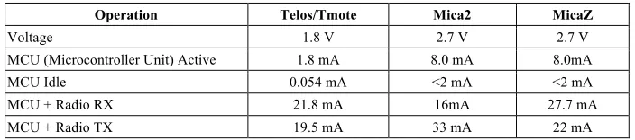
Table 1. Comparison of energy consumption of sensor nodes
Operation Telos/Tmote Mica2 MicaZ
Voltage 1.8 V 2.7 V 2.7 V
MCU (Microcontroller Unit) Active 1.8 mA 8.0 mA 8.0mA
MCU Idle 0.054 mA <2 mA <2 mA
MCU + Radio RX 21.8 mA 16mA 27.7 mA
MCU + Radio TX 19.5 mA 33 mA 22 mA
3.2 Ground augmentation signal design
GPS system is currently the most widely used navigation system in the world. The navigation augmentation signal is based on the GPS satellite signal theory, such that the receiver can capture the enhanced signal with as little change as possible. The compatibility of navigation systems can be improved with the growth of navigation signal augmentation platform technologies, thereby improving their application poten-tial.
In contrast to the GPS signal, the ground augmentation signal includes the naviga-tion message D code and the C/A code, whereas the intermediate-frequency subcarri-er is added. Aftsubcarri-er spreading the D and C/A codes, the spread spectrum code is modu-lated with the intermediate-frequency subcarrier and then converted to the radio fre-quency (RF) carrier band through the second time–frefre-quency change, such as 1575.42 MHz. The GPS signal is easily disturbed by the outside world; thus, the time slot can be controlled in the time domain to strengthen the performance of all aspects of the ground augmentation signal. The launch time and the length of the navigation aug-mentation signal can be defined. To utilize fully the frequency band resources, the multi medium-frequency subcarrier is used, the pseudocode and the navigation mes-sage are adapted for each subcarrier modulation, and the multiplex subcarrier is con-verted to the frequency band after the second time–frequency conversion when the signal is generated. The pseudocode rate of each subcarrier should be adjusted accord-ing to different accuracy requirements.
naviga-tion signals from an ordinary GPS satellite. The ground augmentanaviga-tion system consists of multiple sets of signal generation equipment systems, and each device source sig-nal is generated according to Equation (1).
mod( , )
( ) 2 ( ) ( )sin(2 ( ) )
i i b
M
b
i i i i i
m c m s
m b
t NT t
T
S t P D t c t f m f t g
T ! " # $ $ %% & ' ' (( ) * ' ( = + + + ' ( ' ( ' ( ) *
,
. (1)
In the formula, Si
is the signal launched by the ith device, t refers to time, Pmi is the signal transmitting power of the mth subcarrier, Mi denotes the number of subcar-riers, Di is the navigation message, Ci
represents the pseudorandom code sequence,
c
f is the carrier frequency, !f is the frequency interval between subcarriers, !mi
indi-cates the initial phase of the mth subcarrier, gs is the rectangular window function,
and Tb is the rectangular window function signal cycle called the sub-frame cycle.
The navigation signal contains multiple subcarrier signals and adopts multi-carrier modulation. Each subcarrier can use different pseudocodes Ci
and navigation mes-sages Di, and the multi-carrier is used to realize code division multiplexing through
different modulation codes. Each subcarrier can use different subcarrier frequencies to superimpose and fully utilize the frequency band resources. The independent slotting control of each subcarrier can be used to realize time division multiplexing. There-fore, the navigation signal source can carry a variety of information, distinguish dif-ferent carriers by difdif-ferent PRN codes, realize the efficient transmission of infor-mation, use the same PRN code by multi-carrier redundancy, and considerably en-hance the anti-interference performance of ground augmentation signal transmission. Therefore, the signal source has great flexibility to meet the various needs in the re-search on and application of ground augmentation system.
4
Results
4.1 Navigation ground augmentation signal-generating platform
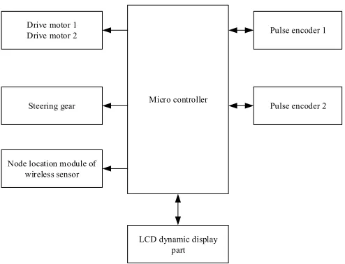
The design of the system hardware platform includes the controller system, the pe-ripheral sensor circuit, the external RAM, the FLASH extension, the debugging inter-face, and the circuit design of the functional modules. The composition of each hard-ware part is introduced according to the function of the system. Figure 2 shows the basic structure of the system function hardware platform.
Drive motor 1 Drive motor 2
Steering gear
Node location module of wireless sensor
Micro controller
Pulse encoder 1
Pulse encoder 2
LCD dynamic display part
Fig. 2. Block diagram of control system hardware
anti-interference capability, and low energy consumption. It has 6-route PWM out-puts, two 32-bit timing counters, and 47 general I/O ports. Thus, the LPC2129 is selected for the main controller to realize the proposed navigation ground augmenta-tion system with stable performance. The system includes the following parts: multi-sensor information fusion technology, the rudder part, the multi-sensor node location, the controller part, the driving circuit, and the LCD dynamic display part.
4.2 Design of baseband/intermediate-frequency module
The quality of augmented signal generated by the navigation signal augmentation platform has a significant influence on the performance of the radio navigation sys-tem. According to the designed signal source, as many as 10 subcarrier IQ signals are generated on this platform. Each subcarrier IQ has the same independent carrier gen-eration mechanism, symbol modulation, and time slot control and can be controlled according to the demands. Multi-channel subcarrier IQ data are generated and stacked in the FPGA and then converted by the high-speed D/A module to generate interme-diate-frequency IQ signals. Finally, they are mixed with the local RF carrier to the RF band.
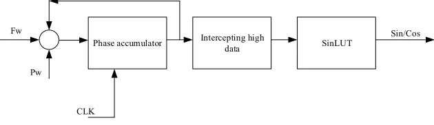
Phase accumulator Intercepting high data SinLUT Sin/Cos
CLK Fw
Pw
Fig. 3. Principle structure of general DDS
In Figure 4, Fw represents the frequency control word of the carrier, and Pw indi-cates the initial phase control word of the carrier. The carrier NCO is operated in accordance with the current input clock. The frequency control word is an input to the phase accumulator, which is a binary coded phase increment value. The phase accu-mulator includes an accuaccu-mulator and a register and feedbacks the output of the regis-ter to the input end of the adder, thereby accumulating the function. The phase accu-mulator accumulates the frequency word incrementally under the excitation of a sin-gle clock pulse, and the phase increment adds one step length and finally outputs the step length. The output of the phase accumulator connects to the address input of the positive cosine lookup table. Under the excitation of the system clock pulse, the phase accumulator is constantly accumulating, that is, checking the table continuously. Fi-nally, the amplitude data of the required frequency are obtained from the lookup table. The frequency control word, the system clock frequency, and the width of the phase accumulator determine the frequency of the carrier NCO output signal.
4.3 Design of RF module and timing synchronization module
The output of the baseband intermediate-frequency module is a digital carrier sig-nal with modulated data; however, the RF part can only handle asig-nalog sigsig-nals. Thus, the signal output from the baseband intermediate-frequency module is converted to digital mode. Through the D/A module, the high-speed digital intermediate-frequency signal can be transformed into an analog intermediate-frequency signal. After the conversion of the D/A module, the intermediate-frequency analog IQ signal must be fused to the RF. Quadrature conversion is a primary modulation of baseband I and Q signals and is widely used in the field of communication. After the multicarrier super-position, the two-path orthogonal I (t) and Q (t) baseband signals are multiplied by the subcarrier and the phase-shift 90° carrier of the local system oscillator to form the final navigation RF signal.
In view of the difference of the batches of the hardware signal platform, the multi-ple augmentation signal platform is incompatible with the acquisition of the 1 PPS pulse trigger signal, which requires the system to support the delay trigger function. After the detection of the external trigger signal, the internal system can delay the entire clock cycle and start the signal generation. Consequently, the internal system can modulate according to the actual measurement of the intrinsic delay value of the equipment, so that each signal augmentation signal source after the network can begin to produce the signal at the same time. Figure 4 shows the diagram of the connection of time synchronization control module.
REF IN
1PPS
Serial port parsing Level
conversion TXD 10M 1PPS
Fig. 4. Diagram of the connection of time synchronization control module
4.4 Ground augmented receiving platform
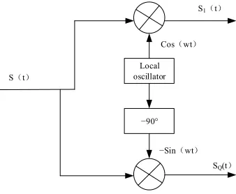
The ground augmented receiving platform mainly includes the down conversion processing of the received RF signals and the storage of the acquired IQ data. The signal-receiving bandwidth, the reference level of the received signal, the sampling rate, the central frequency, and other functional parameters can be set in the receiving function. On the basis of the transmitter, quadrature conversion is used to process the signal conversion. Figure 5 shows the conversion process.
Local oscillator
!90° Coswt
!Sinwt
St
S1t
SQ(t
The acquisition and tracking verification of the enhanced signal data received by the receiving platform must be performed to verify the performance of the navigation signal augmentation platform. When the platform generates a carrier signal, it collects data through the receiving platform and stores it locally. After receiving the signal, the GPS receiver initially performs signal acquisition. Capture processing is the basis for tracking signals and demodulating navigation data. In the GPS system, the naviga-tion message and pseudorandom code are multiplied for spread spectrum processing. The previous data signal bandwidth is broadened from 50 Hz to 1.023 MHz (C/A code) or 10.23 MHz (P code). Therefore, in actual GPS systems, the signal power received by the receiver antenna is extremely weak, and the signal is almost sub-merged in background noise. In this case, the acquisition and tracking process must be down for the weak GPS signal to be extracted from the noise to obtain the final navi-gation data.
Capturing is the 3D search process for the number, carrier frequency, and code phase of a satellite. The GPS receiver can only receive satellite signals in the visible range. Therefore, the satellite number must be determined for tracking and decoding. In the verification of the signal augmentation platform, the pseudocode corresponding to the satellite number can be obtained. The satellite is consistently in a high-speed motion state; thus, the Doppler frequency shift of the received signal exists, and the actual carrier frequency must be determined. GPS signal is a type of code-division multiple-access (CDMA) signal, which distinguishes different satellite signals accord-ing to different spread spectrum codes and realizes signal trackaccord-ing and demodulation through the strong autocorrelation of the pseudocode sequence. The receiver’s receiv-ing signal phase is random; thus, the correct pseudocode phase and the peak value of the autocorrelation result should be obtained through the acquisition of the signal to determine the received signal that contains the pseudocode modulation signal.
4.5 Data tracking analysis
The carrier frequency and code phase values of the GPS signal acquisition process are rough values. The relative velocity of the antenna is constantly changing due to the continuous motion of the satellite. The carrier frequency and the pseudocode phase of the receiver antenna will change continuously due to the impact of the mo-tion of the receiver and the random jitter of the local clock oscillator. Therefore, the signal should be tracked and the satellite navigation message should be demodulated to acquire the carrier frequency and the code phase accurately and continuously. Sig-nal tracking has two main objectives, that is, to realize a carrier tracking loop, which can accomplish the continuous tracking of the carrier frequency and phase in the GPS signal, most of which are realized by the Costas ring; and to code tracking loop to complete the tracking of pseudocode phase, often using delayed locked loop. These two tracking loops exist in almost all GPS receivers. They are coupled and work sim-ultaneously; however, these two rings are essentially phase-locked.
The phase-locked loop (PLL) is mainly used to lock and track the phase of the in-put carrier signal. It belongs to a control loop that generates and outin-puts periodic signals that are consistent with the input signal by changing the loop control parame-ters. When the output and input signal phases are the same, the PLL is locked and shows steady state characteristics. When the phase of the output signal is different from that of the input signal, the PLL is locked and has transient characteristics. If the PLL cannot enter the locked state due to interference, then it will temporarily unlock and eventually lose the navigation data. The main function of the phase detector is to compare the phases of the input and output signals and obtain the phase error signal. The essential difference between different PLLs is the difference between their phase detectors. The loop filter has a low pass characteristic, which is mainly used to filter the high-frequency component and wide-band noise in the error signal, and the con-trol signal is used to concon-trol the voltage-concon-trolled oscillator. Voltage-concon-trolled os-cillator is a frequency modulation osos-cillator, which has a linear control characteristic, and its oscillation frequency changes linearly with the change in control signal. The PLL passes the phase difference between the input and output signals continuously and changes the frequency of the output signal at a certain time. Finally, the output and input signal phases are the same.
The carrier tracking loop continuously changes the frequency of the local carrier, thereby making the locally generated carrier and the received signal carrier frequency strictly consistent. The navigation data will be turned over, which will cause the carri-er of the input signal to turn in phase by 180°. Thus, most carricarri-er tracking rings take the Costas ring, which is insensitive to phase reversal.
4.6 Performance test of navigation signal augmentation platform
of down conversion and storing the data part by receiving the signal generated by the platform. The process also includes capturing, tracking, and verifying data through MATLAB, which can further verify the accuracy of the generated platform signals.
When testing the signal performance of the platform, 1 ! 1.023 MHz, 2 ! 1.023 MHz, 3 ! 1.023 MHz, and three subcarriers are selected without modulation. The trigger mode of the 1 PPS signal is established. After detecting the rising edge of 1 PPS, the signal is generated after the inherent delay. When the initial phase of the three subcarriers is set at 0°, 45°, and 90°, the baseband IQ signal is observed. Figure 6 shows the simulation results.
0.000 0.005 0.010 0.015 0.020 0.025 0.030 0.035 0.040 -1.0
-0.8 -0.6 -0.4 -0.2 0.0 0.2 0.4 0.6 0.8
Fig. 6. Diagram of MATLAB phase superposition simulation
According to the characteristics of subcarrier generation, three single carriers of 100, 200, and 300 Hz are generated through MATLAB. Figure 8 shows the simula-tion when the initial phase is 0°, 45°, and 90°. The comparison of the trends of peak values and waveforms shows that the initial stage of the subcarrier is effectively con-trolled by the platform, which is consistent with the expectation.
0 20 40 60 80 100 1000
1050 1100 1150 1200 1250
Fr
equen
cy off
set
tr
acki
ng
resul
ts(
H
z)
Time(ms)
Fig. 7. Carrier tracking result
The capture and tracking analysis indicates that the navigation message and the navigation message used by the launching platform are consistent, which proves the accuracy and availability of the entire signal augmentation platform.
5
Conclusion
This study mainly discusses the navigation ground augmentation system based on wireless sensor. First, it reviews the research status of WSNs and the navigation sys-tem and then presents the design of the overall framework of WSN node, ground augmentation signal, and signal source. On the basis of the framework, the navigation ground augmentation signal generation platform and the ground augmented receiver platform are designed, and the performance of the navigation signal augmentation platform is tested. The test of the functions of the augmented signal-generating plat-form shows that the functions of the signal generated by the platplat-form conplat-form with the expected design. The expected navigation message data is demodulated success-fully by capturing and tracking the data received on the receiving platform, and the accuracy and availability of the entire signal augmentation platform is confirmed. Therefore, the system satisfies the design requirements and can effectively improve the performance of the navigation system.
6
References
[2]Fan, Q., Sun, B., Sun, Y., Zhuang, X. Performance augmentation of MEMS-based INS/UWB integration for indoor navigation applications. IEEE Sens. J, 2017, vol. 17(10), pp. 3116-3130. https://doi.org/10.1109/JSEN.2017.2689802
[3]Zeng, Y., Zhang, R., Lim, T. J. Wireless communications with unmanned aerial vehicles: opportunities and challenges. IEEE Communications Magazine, 2016, vol. 54(5), pp. 36-42. https://doi.org/10.1109/MCOM.2016.7470933
[4]Dobrev, Y., Vossiek, M., Christmann, M., Bilous, I., Gulden, P. Steady Delivery: Wireless Local Positioning Systems for Tracking and Autonomous Navigation of Transport Vehi-cles and Mobile Robots. IEEE Microwave Magazine, 2017, vol. 18(6), pp. 26-37. https://doi.org/10.1109/MMM.2017.2711941
[5]Zhang, Z., Glaser, S. D., Bales, R. C., Conklin, M., Rice, R., Marks, D. G. Technical re-port: The design and evaluation of a basinscale wireless sensor network for mountain hydrology. Water Resources Research, 2017, vol. 53(5), pp. 4487-4498. https://doi.org/10.1002/2016WR019619
[6]Aldoumani, N., Meydan, T., Dillingham, C. M., Erichsen, J. T. Enhanced Tracking System Based on Micro Inertial Measurements Unit to Measure Sensorimotor Responses in Pi-geons. IEEE Sensors Journal, 2016, vol. 16(24), pp. 8847-8853. https://doi.org/10.1109/ JSEN.2016.2586540
[7]Kumar, G. A., Patil, A. K., Patil, R., Park, S. S., Chai, Y. H. A LiDAR and IMU Integrated Indoor Navigation System for UAVs and Its Application in Real-Time Pipeline Classifica-tion. Sensors, 2017, vol. 17(6), pp. 1268. https://doi.org/10.3390/s17061268
[8]Zhuang, Y., Yang, J., Li, Y., Qi, L., El-Sheimy, N. Smartphone-based indoor localization with bluetooth low energy beacons. Sensors, 2016, vol. 16(5), pp. 596. https://doi.org/10.3390/s16050596
7
Author
Le Le, is associate professor at Changsha Aeronautical Vocational and Technical College, Changsha, Changsha, China ([email protected]). His research interests include navigation ground augmentation system.