Vol.7 (2017) No. 2
ISSN: 2088-5334
Dual-Band Bandpass Filter with Dumbbell Shaped Defective Ground
Structure
M. F. Abdul Khalid
#, Z. Ismail Khan
*, Z. Awang
#, I. Pasya
#, N. Ab Wahab
#, I. M. Yassin
# #Microwave Research Institute, Universiti Teknologi MARA, 40450 Shah Alam, Selangor, Malaysia E-mail: [email protected], [email protected], [email protected]
*
Faculty of Electrical Engineering, Universiti Teknologi MARA, 40450 Shah Alam, Selangor, Malaysia E-mail: [email protected], [email protected], [email protected]
Abstract— A dumbbell shaped defective ground structure (DGS) is implemented to improve the performance of an existing dual-band
bandpass filter topology. The filter design is based on parallel-coupled lines connected to matched transmission lines. Various positions and dimensions of dumbbell DGSs are implemented, and their effects on the filter performance are investigated. It is found that the utilisation of dumbbell shaped DGSs in this topology improve the steepness of the responses for the first and second passbands with centre frequencies of 1.365 and 2.932 GHz respectively. The optimised dimensions of the DGS are 5 x 5 mm2 for both
its rectangular slots connected by a 0.5 mm narrow slot width. The optimised positions of the DGSs are located at the centre and the edges of the parallel-coupled lines. The simulated and measured results of the filter are analysed and discussed in this paper.
Keywords— dual-band; bandpass filter; coupled-line; defective ground structure (DGS)
I. INTRODUCTION
It is well-known that most wireless communication systems are dependent on their radio frequency (RF) components and devices to function. A filter is a crucial component that passes desired frequencies and rejects unwanted frequencies. For the improvement of a filter’s performance especially regarding its scattering parameters (S-parameters), many distinct methods have been tested and validated and among them is defective ground structure (DGS).
A DGS is implemented by purposely etching the ground plane of a device. There are various DGS shapes that have been implemented such as square, rectangular, circular, dumbbell, concentric ring, spiral, L-shaped, U-shaped, V-shaped, hairpin, hexagonal, cross V-shaped, arrow head slot and interdigital DGS [1]. Different shapes and dimensions of the DGSs affect the shield current distribution of the device differently, thus resulting in a controlled excitation and propagation of the electromagnetic waves through the substrate layer [2]. This eventually modifies the properties of line capacitance and line inductance to enhance the response of a conventional filter.
Recently, many researches have been reported using DGS to enhance the filter performance. In [3], the effects of dumbbell shaped DGSs on the low-pass and bandpass filters
were analysed respectively. In the case of the low-pass filter with DGS, there was a 7 dB improvement in the return loss performance. The maximum return losses for the low-pass filter with and without DGS were 59 and 66 dB respectively. The cutoff frequency remained unchanged. For the bandpass filter with DGS, there were improvements in its insertion loss, bandwidth, and return loss compared to the filter without DGS. The insertion loss was slightly improved from 3.6 to 2.6 dB, and the maximum return loss increased from 57 to 60 dB. The bandwidth improved tremendously from 200 to 400 MHz.
A compact dual-band bandpass filter with DGS-SIR resonators was designed [4]. A 50 Ω microstrip line with U-shaped slots was built on the top layer and DGS-SIR resonators were etched in the ground plane. The central frequencies of the first and second passbands were achieved at 3.7 and 5.65 GHz respectively. The filter was fabricated on RO4003C substrate, and good agreement was observed between the simulated and measured results. The measured insertion losses for the first and second passbands were attained at 1.8 and 2.1 dB respectively. The measured return losses were achieved at 16.5 and 18.51 dB respectively.
results were in good agreement with simulated results. The measured results achieved insertion losses of 3.6 and 3.1 dB, and fractional bandwidths of 5.8 % and 6.45 % at 2.4 and 5.2 GHz respectively.
A 60 GHz CPW bandpass filter was designed and fabricated with spiral DGS and interdigital structures on the integrated passive device technology (IPD) [6]. A bandwidth of 8.53 GHz with insertion loss of 4.84 dB was reported, and the maximum return loss was 25.6 dB at a centre frequency of 60.81 GHz in the passband. The research attained 14 % fractional bandwidth with a compact size of 0.18 mm2 which was better than other reported similar works.
A compact, balanced ultra-wideband (UWB) bandpass filter utilising half-mode dumbbell DGS and ‘T’ shape multi-mode resonator with short-ended stub was reported [7]. The half-mode DGS was introduced to suppress the wideband common mode and simultaneously achieved a compact design. The proposed filter achieved better than 30 dB common mode suppression within the desired passband.
In [8], three size-reduced bandpass filters using quarter-mode substrate integrated waveguide (QWSIW) loaded with different DGS patterns were proposed. By exploiting different DGS patterns in the QWSIW, over 40 % size reduction can be achieved compared to its conventional counterpart. The best-measured result was obtained in Type III QWSIW with a centre frequency of 8.79 GHz, fractional bandwidth of 9.5 %, insertion loss of 2.15 dB, return loss better than 12 dB and stopband performance of 35 dB.
A novel dual-band bandpass filter consisted of two pairs of microstrip T-stub and nested interdigital defected ground structure with broadside-coupled transition were enclosed in two slow-wave resonant cells [9]. The filter was fabricated on RT5880 substrate, and experimental results showed the two passbands with centre frequencies of 2.18 and 2.43 GHz. The 3-dB fractional bandwidth was achieved at 9.1 and 7.5 % respectively. The results were in good agreement with the simulated results.
In [10], the authors had implemented rectangular shaped DGSs on the ground plane of an existing dual-band bandpass filter topology. The design produced two passbands with centre frequencies of 1.22 and 2.62 GHz. The effects of having two rectangular shaped DGSs located at the top centre and bottom centre of the ground plane improved the return losses in both passbands shown by simulation. The return loss in the first passband was better than 10 dB and in the second passband, the return loss was improved by 3 dB compared to the filter topology without DGS.
In this paper, a dumbbell shaped DGS is utilised to improve the performance of an existing dual-band bandpass filter topology [11]-[14]. To the best of our knowledge, no work has been reported using this proposed filter topology with dumbbell shaped DGS. The filter topology without DGS is initially designed, and the effects of varying dimensions and positions of DGSs on the performance of the filter are investigated. Filters with and without DGSs are fabricated on FR-4 substrates, and the responses are measured. The simulated and measured results are then compared and analysed.
II. MATERIAL AND METHOD
A. Design of Dual-Band Bandpass Filter
Fig.1 Dual-band bandpass filter topology
Fig. 2 The ideal frequency responses of the dual-band bandpass filter
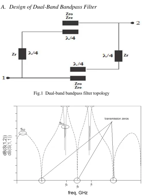
Fig. 1 illustrates the existing topology of the dual-band bandpass filter. The filter consists of characteristic impedances of the transmission lines represented by Zr, even mode, Zre and odd-mode, Zro. Fig. 2 depicts its ideal responses which produce three transmission zeros. f0 is the centre frequency which isolates the two passbands and the deep and sharp rejection regions outside the symmetrical passbands define the dual-band response. The f1 and f2 are the centre frequencies for both passbands.
Fig. 3 illustrates the filter topology where the dimensions were optimised to produce the desired dual-band response. The square ring resonator was initially modelled in HFSS on FR-4 substrate shown in Fig. 4 with the following substrate specifications: relative dielectric constant, ɛr = 4.3, thickness, h = 1.6 mm and loss tangent, tan δ = 0.025.
Fig. 4 3D view of the modelled dual-band bandpass filter
Fig. 5 Dimensions of Dumbell shaped DGS
B. Dumbbell Shaped Defective Ground Structure
The proposed DGS shape for the dual-band bandpass filter is a dumbbell shape shown in Fig. 5. It has a pair of symmetrical square slots connected by a narrow slot. The utilisation of this structure [15] may help in varying the impedance of the microstrip line beyond limit due to the limitation of the line width.
Initially, parametric analysis [16] is conducted on the DGS dimensions as shown in Table I. The dimensions of both square slots are varied while the width of the narrow slot is fixed at 0.5 mm. It is observed that as the dimensions of the square slots increase, the isolation level, f0 reduces to approximately ~25 dB and the return loss reaches ~21 dB. Hence, the optimised dimension is 5 x 5 mm2 with f0 and return loss of 29.3 dB and 30.36 dB respectively.
Fig. 6 shows DGSs etched at different locations in the ground plane to analyse their effects on the filter responses. They are placed under the feed lines, the quarter wavelength lines and the centre and edges of the parallel-coupled lines.
TABLEI
PARAMETRIC ANALYSIS ON DGSDIMENSIONS
Square Slot Dimensions (mm2) Narrow Slot Width (mm) Isolation Level, f
0 (dB) Return Loss (dB)
2.5 x 2.5 0.5 29.12 26.17
5 x 5 0.5 29.30 30.36
7 x 7 0.5 24.84 20.99
Fig. 6 DGS locations in the ground plane of the filter (a) feed lines (b) quarter wavelength lines (c) centre of parallel-coupled lines (d) edges of parallel-coupled lines
III.RESULTS AND DISCUSSION
A. Dual-Band Bandpass Filter without DGS
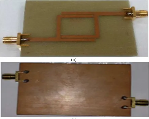
The optimised dual-band bandpass filter is fabricated on FR-4 substrate as depicted in Fig. 7 with similar substrate specifications as mentioned in Section II: relative dielectric constant, ɛr = 4.3, thickness, h = 1.6 mm and loss tangent, tan
δ = 0.025.
Fig. 8 shows the simulated and measured S11 and S21 results of the filter without DGS where a good comparison can be observed. The simulated result produces two distinct passbands centred at 1.365 (f1) and 2.932 GHz (f2) respectively. For the measured result, the centre frequencies of the passbands are slightly shifted. However, the isolation levels, f0 at 2 GHz between the two passbands achieve more than 30 dB although the simulated result is slightly lower. As observed, the steepness of the maximum return loss in the second passband achieves better than 20 dB. The insertion losses for both passbands are around 2.5 dB. The 3dB-bandwidth for the first passband is 500 MHz while the second passband reaches 600 MHz.
(a)
(b)
Freq[GHz]
0.50 1.00 1.50 2.00 2.50 3.00 3.50 4.00
0.00
-12.50
-25.00
-37.50
Simulated S11 Simulated S21 Measured S11 Measured S21
d
B
f1 f0 f2
Fig. 8 Simulated and measured S11 and S21 results
B. Dual-Band Bandpass Filters with DGSs
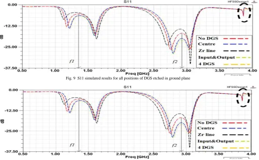
As stated in Section III, the optimised dumbbell shaped DGS is incorporated in this filter. Fig. 9 shows the return loss simulation results for all DGS conditions etched in FR-4 ground planes. A similar pattern can be observed for all conditions. The two most significant responses originate from one pair of DGSs in the centre of the parallel-coupled lines and two pairs of DGSs at the edges of the parallel coupled lines (blue and yellow lines respectively) when compared to the filter without DGS (red line). The best return losses for both conditions are obtained at ~30 dB in the second passband. The DGSs at the feed lines (green line) minimally affect the return loss while DGSs at the quarter wavelength lines is the worst as it slightly diminishes the shape of the first passband (black line). For the best two
conditions, the centre frequencies of both passbands retain the same values as the filter without DGS.
From Fig. 10, similar S21 pattern is achieved for all DGS positions centred at 2 GHz with minimal shift in frequency. It can be seen that by applying one and two pairs of DGSs in the centre and at the edges of the parallel-coupled lines further improves the isolation level of the filter close to 30 dB. The outer rejection levels of the first passband for both conditions have slightly improved compared to the filter without DGS. The insertion losses for both passbands are less than 3 dB. Note that the implementation of DGSs merely affects the bandwidths and insertion losses for both passbands.
Another interesting point is the harmonic distortions (black circle) in both S11 and S21 responses diminish when the two pairs of DGSs are implemented.
Fig. 9 S11 simulated results for all positions of DGS etched in ground plane
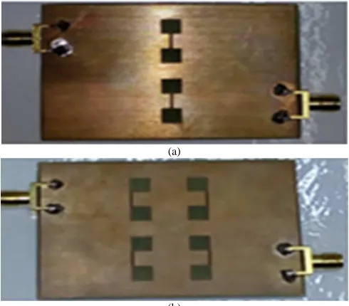
In order to validate the simulated results, the best two conditions were fabricated on low-cost FR-4 substrates with similar specifications in Section II. Fig. 11 shows one, and two pairs of DGSs etched in the filter ground planes.
Fig. 12 shows S11 and S21 results for one pair of DGSs etched in the filter ground plane. As observed, the S11 simulated and measured results show a similar trend (blue and black lines respectively). The steepness of the measured result is evident in the second passband where it attains a maximum return loss of better than 30 dB. However, the centre frequency of the second passband is shifted to a higher frequency of about 100 MHz from the simulated result.
The S21 simulated and measured results overall show a completely different trend. The measured result (red line) does not achieve the expected 30 dB isolation level and is largely shifted to a lower frequency. It is also noticeable that the second passband completely vanishes. However, a positive note can be taken from the first passband where it shows a similar trend to the simulated result, achieving an insertion loss of less than 3 dB. The outer rejection level of the first passband almost reaches 15 dB.
Simulated and measured results for the two pairs of DGSs etched in the filter ground plane are depicted in Fig. 13. It can be observed that the second passband of the measured result has completely suppressed. However, promising outcomes from the first passband where similar trends of measured and simulated results can be observed. The S11 measured result shows a steep response, but the centre frequency is shifted to a lower frequency of about 100 MHz from the simulated result.
The S21 measured result attains an average insertion loss of 3 dB, but the isolation level is vastly shifted to the lower frequency, achieving better than 20 dB.
The distinct trends between the simulated and measured results especially in Fig. 13 can be attributed to the quality of the filter fabrication which may contribute to microwave losses. Also, the substrate material itself, FR-4 which has a relatively high loss tangent of 0.025 may affect the overall performance of the filter.
(a)
(b)
Fig. 11 Etched DGSs on dual-bandpass filter ground planes (a) one pair and (b) two pairs of DGSs
Fig. 12 Simulated and measured S11 and S21 results of filter with one pair of DGSs located in the centre of the parallel-coupled lines
In order to address the substrate issue, a comparison between filters on FR-4 and Taconic RF-45 substrates with the absent of DGS is simulated shown in Fig. 14. It is observed that due to the low loss tangent of the Taconic material, 0.0018 compared to FR-4 of 0.0025, the S11 and S21 simulated responses are more profound than in FR-4 material. The isolation level in Taconic attains better than 40 dB with its passbands obtaining insertion losses of less than 1 dB. The bandwidths of both passbands, however, are
merely affected by the low loss material. The return losses for both passbands are very steep, achieving better than 30 dB. However, the outer rejection level for the second passband is slightly lower than FR-4 but it should be noted that there is no harmonic distortion (black circle). The frequencies for all transmission zeros are better than using FR-4 but slightly shifted. This is due to the contribution from the Taconic dielectric constant of 4.5 as opposed to FR-4 of 4.3.
Fig. 14 S11 and S21 simulated results of the filters on FR-4 and Taconic RF-45 substrates
IV.CONCLUSION
The dual-band bandpass filter with dumbbell shaped DGSs of varying dimensions and positions have been designed, simulated and fabricated on low cost FR-4 substrates. The most promising conditions have been achieved which are one and two pairs of DGSs located in the centre and at the edges of the parallel-coupled lines. From the simulation results, both conditions have achieved the best return losses of approximately 30 dB in the second passband. The isolation levels have attained at 30 dB and the outer rejection levels of the first passband have slightly improved compared to the filter without DGS. The elimination of harmonic distortions in the S-parameter responses have also been highlighted. In order to validate the simulation results, both conditions have been fabricated on FR-4 substrates and experimentally verified. For the one pair of DGSs condition, both the simulated and measured S11 results have a similar trend and a maximum return loss better than 30 dB has been achieved in the second passband. The overall S21 results lack resemblance to one another with the measured second passband has completely suppressed. However, the first passband has managed to follow a similar trend, achieving insertion loss of less than 3 dB and outer band rejection level close to 15 dB. For the two pairs of DGSs condition, the second passband of the measured result has completely suppressed. However, the results of the first passband have a similar trend, achieving an average insertion loss of 3 dB. Overall, the distinct trends between simulated and measured results may be attributed to the fabrication issue and the relatively high loss tangent in FR-4 substrate. A comparison has been made between filters on FR-4 and Taconic RF-45 substrates. The S-parameter simulated results revealed Taconic have been superior, with isolation level achieved better than 40 dB and insertion loss of less than 1 dB in both passbands. As a conclusion, the proposed dual-band
bandpass filter utilizing dumbbell DGSs has a great potential to be incorporated in future wireless communication systems.
ACKNOWLEDGMENT
The authors would like to acknowledge the Ministry of Higher Education Malaysia and Universiti Teknologi MARA for funding this work under the Fundamental Research Grant Scheme (FRGS), grant no: 600-RMI/FRGS 5/3 (71/2015).
REFERENCES
[1] L. H. Weng, Y. C. Guo, X. W. Shi, and X. Q. Chen, "An overview on defected ground structure," Progress In Electromagnetics Research B, vol. 7, pp. 173-189, 2008.
[2] S. H. Zainud-Deen, M. E. Badr, E. El-Deen, K. H. Awadalla, and H. A. Sharshar, “Microstrip antenna with defected ground plane structure as a sensor for landmines detection,” Progress in Electromagnetics Research B, vol. 4, pp. 27-39, 2008.
[3] S. Pragya and T. Raghuvir, "The use of defected ground structures in designing microstrip filters with enhanced performance characteristics," Procedia Technology, vol. 17, pp. 58-64, 2014. [4] C. W. Tang and W. M. Chuang, “Design of a compact dual-band
bandpass filter with DGS-SIR resonators,” in Proc. APMC’15, 2015, p. 1.
[5] S. Xu, K. Ma, F.Meng, and K. S. Yeo, “Novel defected ground structure and two-side loading scheme for miniaturized dual-band SIW bandpass filter designs,” IEEE Microwave and Wireless Components Letters, vol. 25, pp. 217-219, Feb. 2015.
[6] Y. C. Chang, P. Y. Wang, S. S. H. Hsu, T. Y. Lin, C. P. Hsieh, and D. C. Chang, “A V-band CPW bandpass filter with controllable transmission zeros in integrated passive devices (IPD) technology,” in Proc. IEEE IMS’16, 2016, p. 1.
[7] J. Lu, J. Wang, and H. Gu, “Design of compact balanced ultra-wideband bandpass filter with half mode dumbbell DGS,” Electronics Letters, vol. 52, pp. 731-732, Apr. 2016.
[8] Y. M. Huang, Z. Shao, C. J. You, and G. Wang, “Size-reduced bandpass filters using quarter-mode substrate integrated waveguide loaded with different defected ground structure patterns,” in Proc. IEEE IMS’16, 2016, p. 1.
[10] M. F. A. Khalid, Z. I. Khan, M. K. M. Salleh, M. R. M. Ruslan, and N. A. Wahab, “Dual-band bandpass filter with rectangular shaped defective ground structure,” in Proc. IEEE IRFMC’15, 2015, p. 35. [11] N. A. Wahab, Z. I. Khan, M. K. M. Salleh, M. N. Bakhtiar, N. E. A.
Rashid, and K. A. Othman, "Multilayer dual-mode dual-band bandpass filter," in Proc. LAPC’14, 2014, p. 549.
[12] Z. I. Khan, M. K. M. Salleh, and N. Z. Zakaria, “Series-cascaded rings dual-band filter,” in Proc. APMC’10, 2010, p. 1758.
[13] Z. I. Khan, M. K. M. Salleh, and G. Prigent, “Achievable bandwidth of a quarter wavelength side-coupled ring resonator,” in Proc. IEEE SIEA’09, 2009 p. 358.
[14] N. A. Wahab, M. K. M. Salleh, Z. I. Khan, and Z. Awang, “Single-mode ring resonator for microwave bandpass filter applications,” in Proc. IEEE IRFMC’11, 2011, p. 95.
[15] I. M. Yassin, A. Zabidi, M. S. A. M. Ali, N. M. Tahir, H. A. Hassan, H. Z. Abidin, and Z. I. Rizman, “Binary particle swarm optimization structure selection of nonlinear autoregressive moving average with exogenous inputs (NARMAX) model of a flexible robot arm,” International Journal on Advanced Science, Engineering and Information Technology, vol. 6, pp. 630-637, Oct. 2016.