Vol. 5, No.1, 2013, 71-81
ISSN: 2279-087X (P), 2279-0888(online) Published on 13 November 2013
www.researchmathsci.org
71
Annals of
Behavior of Rigid Footing under Inclined and Eccentric
Loading
Pritam Dhar1, Soumya Roy2 and Bikash Chandra Chattapadhyay3
1
MeghnadSaha Institute of Technology Kolkata, West Bengal, India Email: [email protected]
2
Civil Engineering Department, MeghnadSaha Institute of Technology, Kolkata, West Bengal. India, Email: [email protected]
3
Civil Engineering Department, Bengal Engineering and ScienceUniversity,Howrah, West Bengal, India. Email: [email protected]
Received 20 September 2013; accepted 16 October2013
Abstract. It is an important aspect in the design of spread footings to understand the behaviour of surrounding soil when footing are subjected to inclined and eccentric loads.The conventional method of footing design require that footing must possess sufficient safety against failure and settlement must be kept within the allowable value. To have a safe design, the bearing pressure on the underlying ground has to be kept within the allowable bearing values and eccentricity must satisfy the criterion of less than 1/6 of the footing width (e < B/6) so as to avoid tension between the foundation and the soil (Coduto, 2001). Similar condition applies also in case of load having certain inclination with the vertical axis of a footing, conventionally inclination angle, α < . This is the reason why footings subjected to large overturning or rotation also require large footing dimensions which sometimes become uneconomical.
This paper presents the results of laboratory model tests on behavior of a model footing resting on Ganga sand under eccentric – inclined load(through load frame for application of inclined -eccentric load at a time, developed by Roy and Chattopadhyay,2011). The ultimate load carrying capacity of a square & rectangular footing resting on surface dense sand bed has been studied. Initially, the behavior of footing subjected to axial load is studied to compare with the shape factors at the for surface footings.
72 1. Introduction
In civil engineering constructions, foundations may be subjected to inclined loads or eccentric loads or both.
In such situations load carrying capacity is found by some simplified procedures. For example a footing of size LXB having vertical loading with eccentricity eB along
breadth and eL along length from center, is assumed to have loaded area [(L-2eL)
X(B-2eB)]. I.S 6403 [1] recommends a similar procedure. However there are some theoretical
solutions for eccentrically loaded footings (Saran [2], Char, Purakayastha [3]) but not much literature available regarding validation of such theoretical predictions with laboratory or field experimentation results.
Similarly no theoretical formulations are available for finding the bearing capacity of footing subjected to inclined loading through the C.G of the loaded area. So some modifying factors have been suggested for application in bearing capacity equation. I.S 6403 [1] also recommended similar procedure.
However in literature studies regarding the bearing capacity of footing subjected to inclined eccentric loadings, experimental results are not available.
In view of the above there is need for systematic experimental study on footings under inclined loadings to failure with or without eccentricity. Result of such study are expected to bring out the mechanism of such failure under different conditions and ultimate failure loads under such cases may help to develop some relationship with bearing capacity of footings under central loading with those of the footings under inclined load, and also the effects of eccentricity to change the ultimate bearing capacity of footing.
2. Brief review
Any foundation constructed must satisfy two criteria
1) There should not be any shear failure in the foundation medium, supporting the foundation, and
2) This resulting settlement of the foundation must be within permissible limit, depending on type of the foundation and nature of the supporting soil.
73 i) Central vertical load and ii) A horizontal load
For the central vertical load the footing was checked against shear failure while for the horizontal load, it was checked against sliding.
Some theoretical analyses were presented by Meyerhofof [8], Hansen [9], Saran [10] on footing subjected to central inclined loadings. They developed modifying bearing capacity factors to take into effect of load with the inclination of loadings. I.S 6403 [1] have also provided general bearing capacity equation incorporated inclination factors ic,
iq,i. Muhs and Weiss [11] also concluded that the ratio of the vertical component Qu(v) of
the ultimate with the vertical to the ultimate load Qu when the load is vertical (that is, α = 0) and is approximately equal to (1-tanα)2.Dubrova [12] developed a theoretical solution for the ultimate bearing capacity of a continuous foundation with centric inclined load and presented formulations of ultimate bearing capacity of such footings.
From the above review it is observed that sever all methods have been suggested to estimates the bearing capacity of shallow footings subjected to either inclined or eccentric loading. However no report in literature is available to validate the findings of proposed method in actual practice.
3. Scope of present study
A series of central vertical, centrally inclined and eccentric load test on model surface footing were under taken by the authors. Chosen model footings are of different shape and sizes. In the present study, square and rectangular footing subjected to central vertical load followed by central inclined load is given. After that rectangular footing is subjected to the same load condition as square footings. These tests gave the ultimate load carrying capacity of the footing subjected to central vertical loading. From the test results a comparative study was done with the conventional theoretical formulations of IS 6403: 1981.
4. Experimental setup A. Circular Footing Model
Mild steel plates of diameter 20 cm and thickness 5 mm was used as raft footing. Base of the footing model was made rough by gluing a very thin layer of dry sand beneath the circular plates. Footing plates had small pin pointed groves to accommodate steel plunger.
B. Model Test Tank and Load Frame
74
Figure 1: Diagram of load frame with testing tank
C. Foundation Bed Material
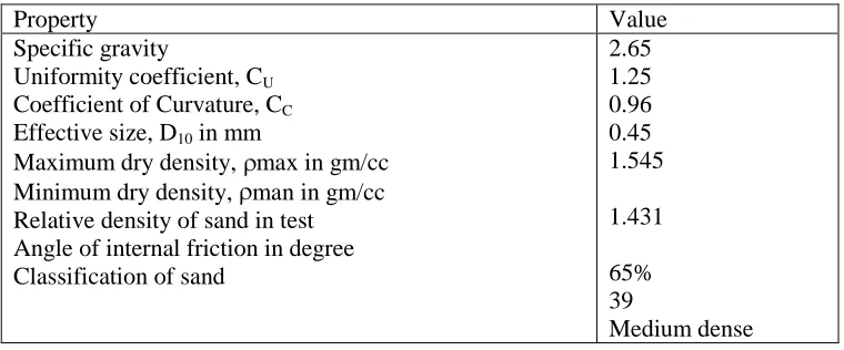
Dry brown uniformly graded Mogra sand obtained from sand mines of Hoogly district, West Bengal was used as soil medium. Grain size analysis, specific gravity test Physical properties of the sand are given in Table 1.
Property Value
Specific gravity
Uniformity coefficient, CU
Coefficient of Curvature, CC
Effective size, D10 in mm
Maximum dry density, max in gm/cc Minimum dry density, man in gm/cc Relative density of sand in test Angle of internal friction in degree Classification of sand
2.65 1.25 0.96 0.45 1.545
1.431
65% 39
Medium dense
Table 1: Physical properties of Sand
5. Experimental procedure
75
complete load-settlement behavior till the ultimate shear failure.The detailed test program for the present study is mentioned Table 1 and Table 2.
6. Test program
Type of footing
Size No. of test Total
test
Square 175 x 175
00
3
6 150
300
Rectangular 150 X 210
00
3 150
300
Table 2: Test Schedule for square footing and rectangular footing subjected to vertical and inclined centric loading
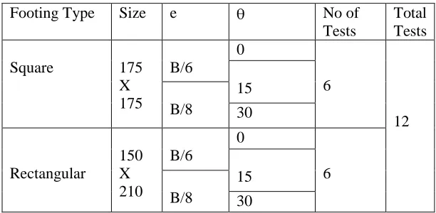
Footing Type Size e No of
Tests
Total Tests
Square 175 X 175
B/6
0
6
12 15
B/8 30
Rectangular
150 X 210
B/6
0
6 15
B/8 30
Table 3: Test Schedule for square footing and rectangular footing subjected to vertical and inclined eccentric loading
Footings were subjected to central monotonically increasing inclined loading at chosen inclination angle to vertical till failure. The angle was varied through 15 degree to 30 degree.
The results of the test series gave an opportunity to measure variation in ultimate bearing capacity of footings with change of inclination of loading. These results were further compared with theoretical values from available literature.
7. Test results
Initially the each of the square and rectangular model footing were subjected to monotonically increasing load to failure with inclination of load to vertical being 0°, 15° and 30°. From the load settlement curves, the ultimate load in each case was determined.
76
loading to failure not centrally, but at a point with double eccentricity ex , ey where ex =
vary from B/6 and B/8 and ey varied from L/6 and L/8. For this case also ultimate load
carrying capacity was also obtained from load-settlement curve.
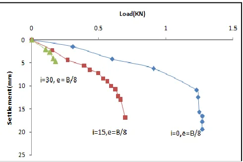
Load-Settlement curves on square plate (175 x 175)mm under vertical and inclined loading at center of footing are shown in Fig. 2 and load-Settlement curve on rectangular plate (150 x 210)mm under vertical and inclined load at center of footing is shown in Fig 3.
Figure 2: Load-Settlement curve on square plate Figure 3: Load-Settlement curve Applied at center at various inclination angle rectangular plate applied at various
inclination angle.
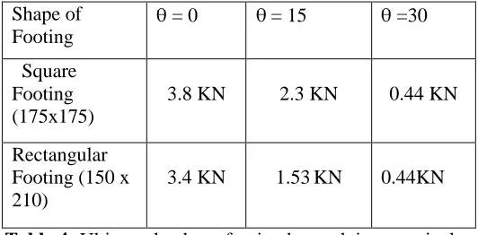
The ultimate load in this both cases was found from the load – settlement curves and tabulated in Table 1.
Shape of Footing
= 0 = 15 =30
Square Footing (175x175)
3.8 KN 2.3 KN 0.44 KN
Rectangular Footing (150 x 210)
3.4 KN 1.53 KN 0.44KN
Table 4: Ultimate loads on footing by applying centric loads
In the second series, load were applied at two way eccentricity 1= (B/8, L/8), 2
=(B/6, L/6) for rectangular plate and 1=(B/8,B/8) , 2 = (B/6,B/6) for square plate in
vertically to 30° with considered 15° at square plate. Fig 4 for 1 eccentricity and fig 5 for
2 eccentricity.
Then load were applied similarly as before at B/8 and B/6 eccentricity in vertically to 30° with considered 15° at rectangular plate. Fig. 6 for 1 eccentricity and fig
77
Figure 4: Load-Settlement diagram of square plate by applying at eccentric B/8 in various inclination angle.
Figure 5: Load-Settlement diagram of square plate in B/6 eccentricity in various inclination angle
78
Figure 7: Load-Settlement diagram of rectangular at B/6 eccentricity at various inclination angle.
Table 5: Ultimate of loading by applying eccentric load at B/8 eccentricity at various inclination angle
Table 6: Ultimate of loading by applying eccentric load at B/6 eccentricity at various inclination angle
8. Discussion of test results
Ultimate load of footing under axial vertical load. In this pogramme two model footings , square footings (175X175) and rectangular (150X210) were chosen and placed over dry sand of density 1.36gm/cc and = 41.5°.
Theoretical values of ultimate load from [1] is given by Qult = ½ *B*N *S . where S = Shape factor =0.8 for square footing, and (1-0.4B/L) for
rectangular footing, Corresponding to =41.5° , N = 130.22, = 1.36 gm/cc, B= 175 mm. For the experimental value of the ultimate load S is back calculated for both square and rectangular plate. Both theoretical and experimental values are compared in Table 7.
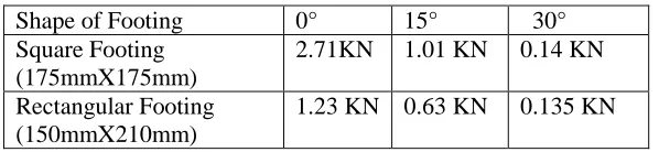
Table 7: Compares of Shape factor between theoretical and experimental. Shape of Footing 0° 15° 30°
Square Footing (175mmX175mm)
2.71KN 1.01 KN 0.14 KN
Rectangular Footing (150mmX210mm)
1.23 KN 0.63 KN 0.135 KN
Shape of Footing =0 =15 =30
Square Footing (175x175) 1.08 KN 0.42KN 0.062 KN Rectangular Footing (150x210) 0.92KN 0.42 KN 0.11 KN
Shape type
I.S.Code (S ) Test value
79
It is observed that ultimate load and shape factor S is moral less same for square footing, and for rectangular footing experimental value is higher than theoretical value. Hence prediction by I.S-6403, through slightly lesser than experimental value but safe value.Ultimate load at footings under inclined load at center.
As the square and rectangular model footing were subjected to monotonically increasing inclined load to failure but loading point is at the center of the footing. Test were conducted for inclination of load being 0°, 15°, 30° respectively. Ultimate load of such footing placed on dry sand is given by Qult = ½ *B*N *S .i , Where i = Inclination
Factor = (1-α/ )2. Theoretical value of S for square plate is 0.8 and (1-0.4 B/L) for rectangular plate and in this case i for 15° and 30° inclination are 0.40 and 0.07 respectively.From the experimental values of the failure load i was determined assuming theoretical values of S which were found both same in theoretical and experimental studies for axially loaded footings earlier. Experimental and theoretical value is shown in Table 8.
Table 8: Compare of inclination factor between theoretical and experimental when E=0.
8.1. Effect on eccentricity on vertical load carrying capacity of footing
In third series both the square and rectangular footing was subjected to monotonically increasing vertical load to failure but loading point has two way eccentricity, , and was varied through 0, 1 , 2 as described earlier.
For eccentrically loaded on vertical direction [1] recommends Qult = 0.5 B * * N * S
where,
B = (B-2eB), L = (L-2eL)
and for rectangular footing , S=(1-0.4 B /L )
Theoretical values of S and experimental values of test value were described in Table 7 From the table it is observed that theoretical experimental value S is moral less same when loading is axial. But for both square and rectangular plate with increase of eccentricity but vertical loading S value does not remain constant. But goes on increase of eccentricity.
However for square plate rate of increase of S is seem to be higher compare to the rectangular plate. But I.S. Code does not satisfy any changes in the value of S with change of eccentricity.
Effect of inclination of loading when loading point is various eccentricity.
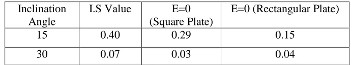
Both the model footing was subjected to loading to failure at various inclination while the loading point has different eccentricity. And the inclination factor i is tabulated in table 9.
Inclination Angle
I.S Value E=0 (Square Plate)
E=0 (Rectangular Plate)
15 0.40 0.29 0.15
80
Table 9: Tabulation of inclination factor
The ultimate load carrying capacity of different eccentricity was tabulated in table 3, where it is observed that due to eccentricity, vertical load carrying capacity decreases when load is acting at a point over the footing eccentricity.
However if the load act at an inclination the load carrying capacity factor decrease at an increasing rate in fact as the inclination increases. The lateral component of load increase leading to sudden sliding failure of footing itself . It is to be remember further we think the increasing the inclination of further load. Vertical load component decreases causing the decreases of frictional resistance at the base of footing.
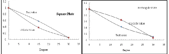
8.2. Effect on inclination of load or load carrying capacity
To investigate the effect of inclination load act at center on the load carrying capacity of the foundation, non dimensional figure has been made, in where , where Q =
Ultimate load when inclined = i and Quv is the ultimate load when i= 0 degree has been
plotted against inclination of the load i in Fig.8 and Fig 9. On the same plot the theoretical values are shown against inclination of load. In Fig.8 the plot is made for square plate and in Fig. 9 same plot has been shown for rectangular plate.
9. Conclusion
From the series of loading tests on square and rectangular model footing, with increasing the load to failure under vertical or inclined loading, the loading being applied centrally or with certain eccentricity with respect to the both axis of footings, following conclusions may be draw.
1) For centrally loaded footing in vertical direction the ultimate bearing capacity of the square footing are found to be higher than that of the rectangular footings. Base area of the footings being nearly same. For vertical centric loading square footing found to be carry much higher load.
IS Square Plate Rectangular Plate e=0 e=B/8 e=B/6 e=0 e=B/8 e=B/6
15 0.40 0.29 0.00643 0.0048 0.15 0.0090 0.0043
30 0.07 0.03 0.00089 0.00069 0.04 0.0019 0.0015
Figure 8: Non dimensional diagram compares in square.
81
2) The predicted theoretical values of ultimate load from I.S.Code – 6403 always gives safe and conservative value compared to experimental values for both the shapes of footings. The co-relation between experimental and codal value is much more consistent than corresponding values from other theoretical models.
3) For both the shape of footings when inclination of centrally acting load with vertical increases , the load carrying capacity falls and when the inclination approaches 30 degree decrease is remarkable and tends to decrease to very low values. This is true for both the cases of footings and also for any eccentric loading.
4) With increase of eccentricity of applied loading whether vertical or inclined, load carrying capacity also decrease and I.S.Code 6403 provides very consistent but safe value.
5) Irrespective of eccentricity the load carrying capacity of footing decreases with increase in the angle of inclination of loading. As the inclination of loading increases the load carrying capacity decreases drastically to a low value as with increase of inclination. The horizontal component of load becomes more and there the resistance offered by the soil bellow, in horizontal direction becomes operating to cause failure by sliding.
REFERENCES
1. Code of practice for determination of breaking capacity of shallow foundation (First Revision)-Bureau of Indian Standard, New Delhi, (1981).
2. Terzaghi, Theoretical Soil Mechanics, John Willey, New York,(1943).
3. G.G.Mayerhof, The bearing capacity of foundation under eccentric and inclined loads in proe III international conference on soil mechanics, Foundation Engg, Switzerland (1953).
4. J.B.Hansen, A general formula for bearing capacity, Danish Geotechnical Institute, Bulletin (1961).
5. G.G.Mayerhof, The ultimate bearing capacity of foundation, Canadian Geotech J,I (1),16, (1963).Page no 28-30
6. Saran, Bearing capacity of Footings under inclined loads, Seminar on foundation problem, New Delhi (1971).
7. S.Prakash and S.Saran, A new method for designing eccentricity loading footing, Journal Indian Geotechnical Society, 3 (1) (1973) 357-359.
8. H.Muhs and K.Wesis, Inclined load test on shallow strip footings in proc VIII international conference soil mechanics foundation and engineering, Moscow 1.3 (1973).
9. G.A.Dubrova, Interaction of soils and structures Rechnoy Transport, Moscow, (1973).