Utilization and Validation of hydraulic formula
to optimize pipeline diameter in waterworks
~Downsizing of water facilities to prepare for decrease in water demand due
to population decline~
Yoshinori Shishido
1*, Koichi Sato
1, Haruka Utada
1and Kazunori Nakai
1*†1 Yokohama Waterworks Bureau
155 Mamedo-cho, Kohoku-ku, Yokohama-shi, Kanagawa, 222-0032, Japan .
Abstract
In order to optimize and downsize pipeline diameter to prepare for water demand decrease in the future, we conducted validation to apply the Hazen-Williams formula to existing pipeline. We focused on the flow velocity coefficient (hereafter referred to as, “C”) and validated it through a pipeline network simulation and field experiments. As a result, the present value for C that is uniformly adopted in Japan should be modified for existing pipeline. Furthermore, variance in C due to the differences between the inner linings of pipeline was verified. We evaluated the effectiveness of downsizing of pipeline diameter with the result of this study, and we confirmed that this study contributes to optimizing and downsizing pipeline diameter.
1
Introduction
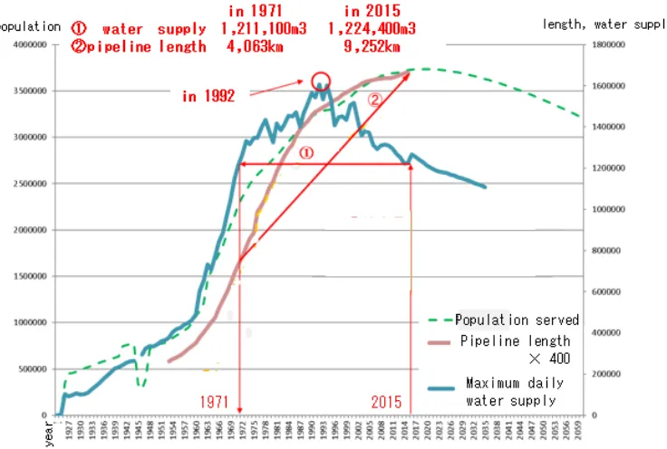
Yokohama Waterworks Bureau (hereafter referred to as, “YWB”) has expanded its waterworks facilities to meet the increasing water demand due to population growth, but it is predicted that population growth will shift towards decline in the near future. A downward tendency of water demand has continued since the peak of 1,600,000m3 in 1992, and water demand in 2015 was 1,220,000m3, almost the same as 44 years ago in 1971. Whereas, pipeline length has been extended more than doubled from 4,063km in 1971 to 9,252km in 2015 due to expanding residential areas. Regarding pipeline diameter, flow velocity of most pipelines in Yokohama is under 0.4m/s, which is considered the minimum velocity to prevent formation of sediments.
* Masterminded EasyChair and created the first stable version of this document † Created the first draft of this document
Volume 3, 2018, Pages 1955–1961
If the present pipeline length and diameters are retained in the future in spite of a decrease in water demand, stagnant water and turbid water will form due to the decreased flow velocity, and necessity to regularly discharge them will increase the cost of maintenance. Furthermore, YWB continually replaces old pipes with earthquake-resistant pipes that have an assumed lifespan of 80 years. Therefore, future decrease in water demand needs to be taken into consideration when selecting pipeline diameters, otherwise, the discrepancy between actual pipeline diameter and optimal pipeline diameter for water demand will become larger. At the same time, YWB is also required to keep necessary pipeline diameter to meet present water demand. We conducted validation to apply the Hazen-Williams formula to existing pipeline as one of the solutions for this difficult issue.
Figure 1 Transition of population served, pipeline length and maximum daily water supply
2
Problem with practical application of the Hazen-Williams
formula to actual pipeline
YWB’s pipeline network simulation uses the Hazen-Williams formula to select the size of the pipeline. The Hazen-Williams formula is an equation describing the relationship between flow rate (Q) and friction head loss (hf), and is calculated based on the conditions of internal pipeline diameter (D), length (L) and flow velocity coefficient (C).
Q = 0.27853 ∙ C ∙ D-../∙ 01 23
4.56
(1)
Still, if we consider all possible sources of head loss individually, the calculation becomes complicated. For this reason, we use C that includes total head loss. In Japan, C =110 is uniformly recommended without consideration of differences between new and existing pipes and other conditions, and YWB has also adopted C=110 to calculate pipeline diameter. However, the actual value for C should be different based on pipe’s age and inner linings. We believe that we must adopt the value for C that is closer to the actual value to optimize pipe diameter. We assume that the actual value for C of existing mortar lining (hereafter referred to as “mortar”) is more than 120 and actual value for C of existing fusion-bonded epoxy coating (hereafter referred to as “epoxy”) is more than 140, judged from the reference material for evaluating C of new pipeline [1] .
3
Validation of flow velocity coefficient
Experiments and evaluations have been conducted on C of new pipeline, but there are few data available on C of existing pipes. However, for practical use, it is necessary to consider the value of C in regard to the aging of water pipes. Therefore, we conducted field experiments and pipeline network simulation with the existing pipes to validate C.
We adopt mortar lining for pipes over diameter 100mm in Yokohama at present, so we firstly verified C of existing mortar-lined pipes. Next, we verified C of fusion-bonded epoxy coating that is considered to have higher C than that of the mortar lining.
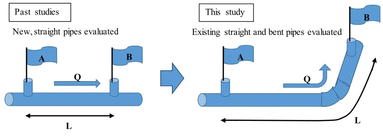
Figure 2 Field experiments to calculate C
3.1
Existing mortar lining
3.1.1 Field experiments with existing pipe
Field experiments was conducted to verify C of existing mortar lining. Experimenting method involved measuring head loss at point A and point B, and calculating flow velocity coefficient of each flow rate with Hazen-Williams formula under the condition of constant flow rate in pipeline of internal diameter (d) including vent pipes. Pipeline data: DIP material, diameter 150mm, aged 29 years and 33 years, length 241m and 242m, flow rate 20~60m3/h and 50 ~80m3/h. We measured water pressure at point A and point B while discharging water from fire hydrant at flow rate 20~60m3/h and 50 ~80m3/h, and calculated C. The results are shown in Tables 1 and 2.
A
B
L L
A B
Q Q
Past studies This study
New, straight pipes evaluated Existing straight and bent pipes evaluated
Table 1 Results of first experiment
flow rate(m3/h) flow velocity(m/s) head loss(m)【average】 C【average】 20 0.332 0.287 141.5 40 0.664 0.859 136.3 60 0.996 2.118 123.7
Table 2 Results of second experiment
flow rate(m3/h) flow velocity(m/s) head loss(m)【average】C【average】 50 0.83 1.2 136.7 60 0.996 2.0 124.6 70 1.161 2.5 131.0 80 1.327 3.1 133.5
3.1.2 A comparison between simulation value of network analysis and actual value
Firstly, we installed water pressure gauges at five points (i-ⅴ) in four gravity flow areas.ⅰ. Trunk pipelines directly connected from a water reservoir
ⅱ. Pipeline of diameter 200mm or 300mm that has enough flow rate
ⅲ. Two pipelines of diameter 100mm or 150mm that have enough flow rate
ⅳ. Pipeline in low water pressure area
Next, we calculated the simulation value under the situation of C=110 and 120 at water pressure measurement point. We adopted hourly average (m3/hour) of daily average (m3/day) of water demand for past year as water demand for the condition of simulation.
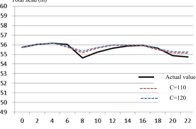
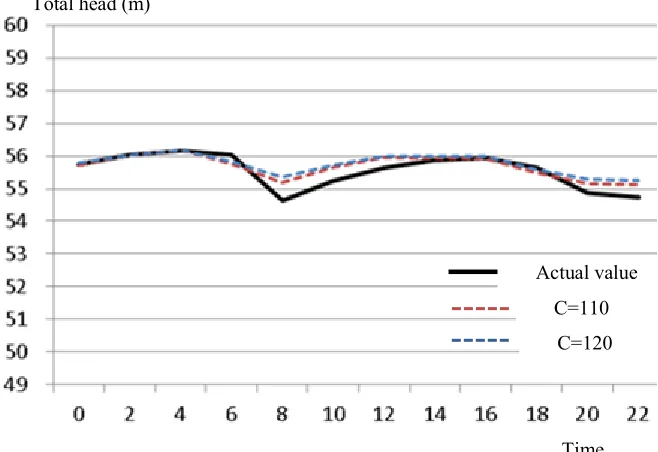
Finally, we compared water pressure between simulation value and actual value. The results are shown below in Figures 3 and 4.
Total head (m)
Time Figure 3 Diameter 200mm or 300mm in Kanazawa gravity area
Total head (m)
Time Figure 4 Diameter 200mm or 300mm in Ushikubo gravity area
3.1.3 Summary of the results
The results of field experiments show that C is more than 125 under the condition of flow rate from 0.3m/sec to1.3m/sec in mortar-lined pipe with an age of approximately 30 years. The result of the comparison between simulation value and actual value shows that they are almost same. Therefore, we can adopt C=120 instead of C=110 for C of existing mortar-lined pipes.
3.2 Existing fusion-bonded epoxy coating
Existing fusion-bonded epoxy coating is not used for pipelines with diameters over 100mm in Yokohama at present. However, C of existing fusion-bonded epoxy coating is expected to be higher than that of mortar lining, so we verified the C to promote downsizing.
3.2.1 Field experiments with existing pipes
We conducted the field experiments to verify C of existing fusion-bonded epoxy coating. Experimenting method involved measuring head loss at point A and point B, and calculating flow velocity coefficient of each flow rate with Hazen-Williams formula under the condition of constant flow rate in a pipeline of internal diameter (d) including vent pipes. Pipeline data: DIP material, diameter 150mm, aged 23 years, length 230m, flow rate 20-60m3/h and 60 -100m3/h. We measured water pressure at point A and point B while discharging water from fire hydrant at flow rate of 20-60m3/h and 60 -100m3/h, and calculated C. The results are shown in Tables 3 and 4.
Actual value C=110
Table 3 Results of first experiment
flow rate(m3/h) flow velocity(m/s) head loss(m)【average】 C【average】 20 0.302 0.177 146.1 40 0.604 0.659 135.1 60 0.907 1.467 128.4
Table 4 Results of second experiment
flow rate(m3/h) flow velocity(m/s) head loss(m)【average】C【average】 60 0.907 1.2 143.8 70 1.058 1.7 138.9 80 1.209 2.1 141.0 90 1.360 2.5 144.3 100 1.511 3.2 140.6
3.2.2 A comparison between calculated head loss and actual head loss
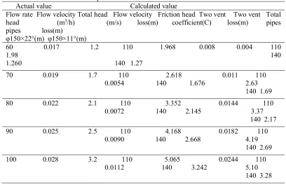
We calculated head loss with the reference material “Water distribution pipes” published by Osaka city water works technology association and compared it with actual values. The results are shown in Table 5
Table 5 Comparison between calculated value and actual value Actual value Calculated value
Flow rate Flow velocity Total head Flow velocity Friction head Two vent Two vent Total head (m3/h) (m/s) loss(m) coefficient(C) loss(m) pipes
pipes loss(m) g φ150×22°(m) φ150×11°(m)
60 0.017 1.2 110 1.968 0.008 0.004 110 1.98 k 140 1.260 140 1.27
70 0.019 1.7 110 2.618 0.011
0.0054 l 140 1.676 2.63 110 f
140 1.69 80 0.022 2.1 110 3.352 0.0144
0.0072 g 140 2.145 3.37 110 g
140 2.17 90 0.025 2.5 110 4.168 0.0182
0.0090 e 140 2.668
110 4.19 f
140 2.69 100 0.028 3.2 110 5.065 0.0244
0.0112 f 140 3.242
110 5.10 g
3.2.3 Summary of results
The results of field experiments show that C is more than 140 under the condition of flow rate from 0.3m/sec to1.5m/sec in fusion-bonded epoxy coating pipe with an age of approximately 23 years. Furthermore, we compared actual head loss with calculated head loss under the situation of C=110 and C=140 with flow rate from 60m3/h to 100m3/h. The results show that total head loss is overestimated with C=110, and total head loss with C=140 is closer to the actual value. Influence of vent pipes on total head loss was clarified to be small.
These results tell us that we should use C=140 instead of the present 110, as doing so will help optimize pipeline scales as well as drive forward downsizing. We also confirmed that C of fusion-bonded epoxy coating is superior to that of mortar lining.
In addition to C, epoxy is superior in terms of effective cross-sectional area because of its thinner coating compared to mortar. Therefore, if C is assumed to be 140, it is estimated that 1,000m of mortar pipeline with diameter of φ150mm could be reduced to φ100mm with epoxy for 160m out of the 1,000m. Furthermore, we calculated the head loss, assuming the replacement from mortar of diameter φ150mm with flow velocity 0.2m/s to epoxy of diameter φ100mm as an example. The rise of head loss was small. Thus, we would be able to downsize the pipelines that already have excessive water pressure. The rise of head loss is shown in Table 6.
Table 6 Rise of head loss
4
Conclusion
We conducted validation of C using the Hazen-Williams formula to select the optimal sizes of pipe diameter. As a result, we found that the current generally accepted C=110 tends to overestimate total head loss, while validity of C=120 for mortar and C=140 for epoxy were verified. The variance in C due to the difference of inner lining was also verified. Thus, when existing old mortar pipe is replaced with new earthquake-resistant pipe, fusion-bonded epoxy coating should be selected due to its superiority in C and effective cross-sectional area for downsizing. However, the cost of material is more expensive than that of mortar lining. We will verify the effectiveness of downsizing and construction cost to decide which inner lining we should select. In the case of Yokohama where there is already an excess of water pressure, so most pipelines can be downsized from the present diameter to a smaller one.
References
[1]Japan Ductile Iron Pipe Association, The coating and lining,2007,pp.17
[2]Osaka city waterworks technology association, Water distribution pipe,3.4head loss
in case of the flow rate is fixed before downsizing Afer downsizing
diameter, inner lining φ150mm mortar φ100mm epoxy
flow velocity 0.2m/s 0.47m/s