*
Corresponding Author Email Address: [email protected]
Derivation of Specific Heat Rejection Correlation in an SI Engine; Experimental and
Numerical Study
Ali Qasemian 1*, Pouria Azarikhah 2, Sina Jenabi Haqparast 3 1
Assistant Professor, Faculty of Automotive Engineering, Iran University of Science and Technology, Tehran, Iran
2
Master of Science, Faculty of Mechanical Engineering, Iran University of Science and Technology, Tehran, Iran
3
Master of Science, Faculty of Automotive Engineering, Iran University of Science and Technology, Tehran, Iran
ARTICLE INFO A B S T R A C T Article history:
Received :30 Jan 2018
Accepted: 3 Jun 2018
The thermal balance analysis is a useful method to determine energy distribution and efficiency of internal combustion (IC) engines. In engines cooling concepts, estimation of heat transfer to brake power ratio, as one of the most significant performance characteristics, is highly demanded. In this paper, investigation of energy balance and derivation of specific heat rejection is carried out experimentally and numerically. Experiments are carried out on an air-cooled, single cylinder, four-stroke gasoline IC engine. The engine is simulated numerically and after validation with experimental data, the code is run to find out total and instantaneous thermal balance of engine. Results indicate that about one-third of fuel energy is converted to brake power and major part of energy is dissipated through exhaust and heat transfer. Experimental and numerical results show that by increasing engine speed, heat transfer to brake power ratio decreases. It is also observed that increasing engine speed leads to increase of exhaust power to brake power ratio. Finally two correlations for estimation of heat transfer and exhaust power to brake power ratios are obtained.
Keywords:
Internal Combustion Engine; Total Thermal Balance; Heat Rejection Correlation; Instantaneous Energy Balance;
1.
Introduction
Fossil fuels play an extremely important role in transportation industrial all over the world. Most of the internal combustion engines consume liquid petroleum-based fuels in order to produce effective power. It is impossible to convert total fuel energy to output power and major part of fuel energy is wasted in form of heat losses, friction and exhaust. Thermal balance analysis is a useful method in order to determine energy distribution and performance characteristics of engines. It is highly significant to specify each term of energy
balance equation in various engine operating conditions.
Ozcan and Soylemez [1] investigated the effect of water injection on a spark ignition engine thermal balance and performance experimentally. They used a four stroke, four cylinder engine with LPG as fuel. Different water to fuel ratios by mass were used with variable engine speed ranging from 1000 to 4500 rpm. Their results showed that as the water injection level to the engine increased, the percentage of useful work
International Journal of Automotive Engineering
Journal Homepage: ijae.iust.ac.ir
S
N:
2
0
0
8
-9
8
9
9
2680 International Journal of Automotive Engineering (IJAE) increased, while the losses other than unaccounted
losses decreased. Additionally, the specific fuel consumption decreases, while the engine thermal efficiency increases.
Magno et al. [2] investigated the energy distribution and the waste heat recovery characteristics of a compression ignition engine at different engine speeds and loads. The experimental activity was carried out on a three-cylinder, 1028 cc engine. Tests were performed with diesel fuel and 20% biofuel blend. The quantity and the quality of the waste heat energy were studied through energy and exergy analysis. It was found out that the addition of 20% biodiesel blend to diesel fuel does not affect significantly the brake fuel conversion efficiency. On the other hand, biodiesel blend allows to reduce the combustion noise and the pollutants emissions in most of the operating conditions. Yusri et al. [3] conducted an experimental investigation of butanol as an alternative fuel. A four stroke, four-cylinder gasoline engine was used to investigate the engine combustion emissions and thermal balance characteristics using 2-butanol-gasoline blended fuels. The thermal balance analysis mainly exhibited an improvement in effective power, cooling energy and exhaust energy.
Khoobbakht et al [4] analyzed the exergy and energy in a four-cylinder, diesel engine using blended levels of biodiesel and ethanol in diesel fuel with the assistance of the first and second laws of thermodynamics. They also investigated the effect of operating factors of engine load and speed as well as blended levels of biodiesel and ethanol in diesel fuel on the exergy efficiency. Their results depicted that the exergy efficiency decreased with increasing percent by volume biodiesel and ethanol fuel. The fuel blend of 0.4 L ethanol added to 1 L diesel at 2800 rpm and 20% load was realized to have the least exergy efficiency (8.1%). Also, the results of exergy and energy analysis indicated that the 43.09% of fuel exergy was destructed and the average thermal efficiency was approximately 36.61%.
Duan et al. [5] investigated the fuel utilization efficiency of gasoline-powered vehicle. In order
to evaluate and improve the fuel utilization efficiency, the vehicle energy flow test was conducted on chassis dynamometer under the new European driving cycle (NEDC) of cold starting. Research results showed that the distributions of various kinds of energy flow were largely influenced by vehicle operating conditions. Apart from idling conditions, the brake thermal efficiency of internal combustion engine was mainly between 10% and 35%. At the initial stage of NEDC, the brake thermal efficiency was very low due to the cold starting. Also, the exhaust gas energy was mainly influenced by the mass flow rate of exhaust gas, while its percentage in total fuel energy depended largely on exhaust gas temperature. Moreover, the coolant energy flow was less sensitive to the engine conditions, but its percentage fluctuated widely under the transient conditions of NEDC.
Li et al. [6] studied energy distribution in a diesel engine using low heat rejection concepts. In this study, the low heat rejection operating condition is implemented by increasing the engine coolant temperature. Their results demonstrate that rising coolant temperature yields slight improvements in net indicated fuel conversion efficiency, with larger improvements observed in brake fuel conversion efficiency.
Ajav et al. [7] investigated the thermal balance of a constant speed stationary compression ignition engine on diesel, ethanol-diesel blends at different loading conditions of the engine. The thermal balance was in respect of useful work, heat lost to cooling water, heat lost through exhaust, heat carried away by the lubricating oil and other losses. They also compared thermal balance of the engine operating on different diesel-ethanol blends. Their results indicate that the thermal balance of the engine operating on 5 and 10% ethanol-diesel blends and fumigated ethanol was not significantly different at the 5% level of significance when compared to diesel. However, in the case of 15 and 20% ethanol-diesel blends, the thermal balance was significantly different compared to diesel.
Gharehghani et al. [8] investigated the thermal balance and performance of a turbocharged gas spark ignition engine. The first law of
International Journal of Automotive Engineering (IJAE) 2681 thermodynamics was used for control volume
around the engine to calculate the output power, transferred energy to the cooling fluid, exhaust gases and also unaccounted losses. Thermal balance tests were performed for various operational conditions. They concluded that by increasing engine load and coolant temperature, the percentage of transferred energy to the exhaust gases increased while the percentage of coolant energy decreased.
Yingjian et al. [9] examined the energy balance and the efficiency analysis for power generation in an internal combustion engine sets using biogas. Their results of energy balance and efficiency showed that the engine set could generate electricity of 70kW. Their results showed that the thermal energy dissipated from the engine exhaust was the greatest term of all thermal balance terms.
Abedin et al. [10] examined energy balance of internal combustion engines using alternative fuels. The basic energy balance theory was discussed in details along with the variations in energy balance approaches and terms. The theoretical energy balance also explored with help of thermodynamics models. There are some significant variations observed in energy balance when the engine operating fuel is changed and devices like turbocharger or supercharger are used to boost the intake air pressure.
Payri et al. [11] conducted experimental methodologies in order to perform and analyze the energy balance to evaluate the potential of different engine strategies. This work deals with the complete description of an experimental energy balance tool, including the comprehensive description of the specific designed experimental installation used to the determination of each energy term involved in the energy balance. A direct injection (DI) diesel engine was used and the influence of the engine speed and load was examined on each energy term. Their results indicated that the variation of the coolant temperature has an almost negligible effect in term of efficiency whilst cooling the air yields improvement.
Durgun and Sahin [12] investigated theoretically to evaluate energy balance for three different DI diesel engines in various conditions. To analyze energy balance, a zero-dimensional multi-zone thermodynamic model was developed and used. From numerical applications, it was determined that, what portion of available fuel energy is converted to useful work, what amount of fuel energy is lost by exhaust gases or lost by heat transfer. In addition, heat balance was analyzed for gasoline fumigation and it was found that brake effective power and brake specific fuel consumption increase and brake effective efficiency decreases for gasoline fumigation for turbocharged diesel engines.
Yuksel and Ceviz [13] studied the effects of adding constant quantity hydrogen to gasoline-air mixture on SI engine thermal balance and performance. A four stroke, four-cylinder SI engine was used in order to carry out this research. Thermal balance tests were conducted for thermal engine efficiency, heat loss through the exhaust gases, heat loss to the cooling water and unaccounted losses, while performance tests were in respect to the brake power, specific fuel consumption and air ratio. The experiments were performed in three different mass flow rates of hydrogen and variable engine speeds ranging from 1000 to 4500 rpm. Their results indicated that supplementation of hydrogen to gasoline decreases the heat loss to cooling water and unaccounted losses, and the heat loss through the exhaust gas in nearly the same with pure gasoline experiments. Furthermore, specific fuel consumption decreases, while the engine thermal efficiency and the air ratio increase.
Taymaz [14] investigated the effect of insulated heat transfer surfaces on diesel engine energy balance experimentally. The research engine was a four-stroke, direct injected, six cylinder, turbocharged and inter-cooled diesel engine. This engine was tested at different speeds and load conditions. Combustion chamber surfaces, cylinder head, valves and piston crown faces were coated with ceramic materials. The results showed a reduction in fuel consumption and heat losses to engine cooling system.
2682 International Journal of Automotive Engineering (IJAE) In this study, an air-cooled, single cylinder, four
stroke IC engine investigated experimentally and numerically. Experiments are conducted in various engine speeds using gasoline. Furthermore, validation is implemented and engine is simulated in order to determine and compare thermal balance terms. In present research, Derivation of specific heat rejection correlation is performed which is not considered widely in previous works. Additionally, instantaneous energy balance in cylinder per cycle is studied in this paper.
2.
Experimental Apparatus
2.1. Engine Test Setup
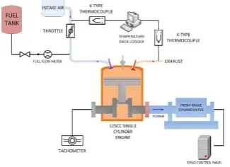
The motorcycle engine which is studied in this research is 125 cc, single cylinder, air-cooled, spark ignition and four-stroke. The engine is coupled with a prony brake dynamometer in order to measure the torque produced by the engine. The engine technical specifications and operation conditions of the experiments are provided in Table 1, Fig. 1[15].
Table 1. Engine Technical Specifications
Cylinder Type Single Cylinder, Four-Stroke
Displacement (cm3) 124.1
Bore (mm) 56.5
Stroke (mm) 49.5
Valves Sorting Two OHC Valves
Compression Ratio 9.1:1
Max. Power (kW) 7.4 @ 8492 rpm
Max. Torque (N.m) 9.23 @ 6997 rpm
Intake Valve Timing 5 Degrees bTDC/35 Degrees aBDC Exhaust Valve Timing 30 Degrees bBDC/5 Degrees aTDC
2.2.
Measurement Equipment
Specific measurement instruments such as thermocouples, flow meter, etc. are used in this experimental study. Temperatures of intake air and exhaust gases are measured by K-type thermocouples. This type of thermocouple can be used with a service temperature range between -270 and +1260 . The sensitivity and measurement accuracy of these thermocouples are 41 and 2.2 respectively[16]. The sample thermocouple and its wire and socket are shown in Fig. 2. A dual channel temperature data logger is used in order to display and record temperatures of thermocouples. Fuel delivery system is fabricated with the assistance of scaled storage tank and a flow meter is used in order to
estimate fuel consumption. A digital tachometer which is attached to the engine is used to measure engine speed and its accuracy is 5 rpm. The accuracy of torque measured by prony dynamometer is 0.1 . Calibration checks of measuring instruments are performed
two times
during each experiment.
Figure 1: Schematic Diagram of Engine Test Setup
International Journal of Automotive Engineering (IJAE) 2683
3.
Numerical Modeling and Simulation
In order to simulate engine thermal balance including performance and heat transfer, a thermodynamic closed system and differential energy equation for small crank angle changes is used. Different parameters such as fuel consumption, valves lift, engine geometry and air to fuel ratio are measured experimentally and applied as simulation inputs. P- is the most significant parameter which is calculated by the implicit differential equation of pressure in the cylinder as given in Eq. (1).
(1)
In Eq. (1), , and are determined by geometry, combustion, and heat transfer sub-models respectively and presented in the following sections. This implicit ODE is solved numerically by forth order Runge-Kutta method.
Figure 2: Sample Thermocouple and Its Wire and Socket
3.1.
Engine Geometry
The volume of cylinder in each crank angle can be obtained by Eq. (2).
(2)
Where V is in-cylinder volume and VC is cylinder
clearance volume. B, l, a, and s are the cylinder bore, connecting rod’s length, crank radius and the distance between the piston pin axis and crank axis respectively.
The distance between the piston pin axis and crank axis can be expressed by Eq. (3)[17].
⁄ (3)
Where is the crank angle.
3.2.
Combustion Model
Wiebe function which is used frequently in SI engines is applied to characterize combustion process in this simulation. The Wiebe function can be expressed as Eq. (4).
[ ( ) ] (4)
Where is crank angle, is the start of the combustion, is the total combustion duration ( to ). Also, a and m are parameters which adjust with engine operating conditions to improve the simulation accuracy[18].
3.3.
Heat Transfer Model
To determine heat transfer rate through cylinder walls, Woschni heat transfer correlation is used as shown in Eq. (5):
(5)
Then the amount of is calculated by Eq. (6)
( )
(6)
The average cylinder gas velocity, (m/s) is given
by Eq. (7).
* ̅ + (7)
3.4.
Engine Energy Balance
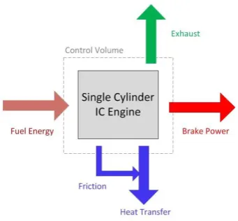
The thermal balance analysis gives useful information on the distribution of supplied fuel energy in the engine systems and identifies the avoidable losses of the real engine process. In internal combustion engines, only a limited part of total fuel energy is converted to effective output as brake power and the rest which is the major part of fuel energy is lost in different ways consists of heat transfer, friction and exhaust.
2684 International Journal of Automotive Engineering (IJAE) Preventing overheating is highly critical in order
to maintain the engine. On the other hand, it is impractical to operate an engine as hot as possible to maximize thermal efficiency. Schematic diagram of energy distribution in internal combustion engines is shown in Fig.3.
Figure 3: Schematic Diagram of Energy Distribution in Internal Combustion Engines
The energy balance of steady flow energy equation in control volume is given in Eq. (8).
̇ ̇ ⁄ (8) Therefore, energy balance can be expressed as Eq. (9).
̇ ̇ (9) Hence, the first law of thermodynamics for control volume around the engine is given in Eq. (10)
̇ ̇ ̇ ̇ (10) Total or supplied fuel energy which enters the engine is introduced in Eq. (11).
̇ ̇ (11) The amount of heat loss with the exhaust gases can be measured by Eq. (12). The specific heat of air at mean exhaust temperature is considered as the average specific heat of the gases [10].
̇ ̇ ̇ (12)
The output power delivered by engine shaft or the engine brake power is given in Eq. (13)[19].
̇ (13)
Where bmep is mean effective pressure, n is the number of cylinders, is displacement volume and N is engine speed in rpm. bmep in this equation can be expressed as Eq. (14)[19]:
(14) imep is indicated mean effective pressure which is given in Eq. (15)[19].
∮ (15)
The friction mean effective pressure (fmep) can be calculated by Terbone’s equation which is shown in Eq. (16)[20].
(16)
Therefore, the unaccounted heat losses include heat transfer, friction and heat carried away by the lubrication oil can be calculated by Eq. (17).
̇ ̇ ̇ ̇ (17)
4.
Validation
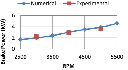
As it mentioned above, experiments are conducted in 3000, 4000, and 5000 rpm using an air-cooled, single cylinder gasoline engine. Simulation results including brake power and exhaust gas temperature are validated with experimental data as shown in Figs. 4, 5. Both of validations have appropriate accuracy which makes the results of numerical investigations reliable. Deviations of brake power and exhaust temperature validations are illustrated in Fig. 6.
International Journal of Automotive Engineering (IJAE) 2685 Figure 4: Brake Power Validation of Engine
Figure 5: Exhaust Temperature Validation of Engine As shown in Fig. 6, the maximum deviation between simulation and experimental results about exhaust temperature is 9.66% and this amount for brake power of engine is 9.09%. This proves that simulations can predict the engine functions by an acceptable accuracy. The amount of deviation is defined in Eq. (18).
| | (18)
5.
Results and Discussion
In this section experimental and numerical results are presented and discussed.
5.1.
Experimental Results
Experiments are performed in various engine speeds including 3000, 4000, and 5000 rpm. Fig. 7 demonstrates distribution of energy in studied small IC engine with the assistance of experimental measurements. As it is shown, all terms of energy balance equation include exhaust power, brake power, and heat transfer have upward trend with respect to the engine speed increment. Brake power in 4000 rpm has
increased by 33.48% compared to 3000 rpm. Meanwhile, exhaust power and heat transfer have increased by 38.11% and 20.57% respectively. In 5000 rpm, brake power and heat transfer have risen by 25.08% and 18.71% in comparison to 4000 rpm.
Figure 6: Exhaust Energy and Brake Power Deviations of Engine
According to experimental data, total thermal balance versus engine speed is presented in Fig. 8. By increasing engine speed, the percentage of exhaust energy increases in contrast to heat transfer. In addition, the percentage of brake power in tested engine speeds remains approximately constant without considerable variations. At higher engine speeds, due to less time of each cycle, there is a reduction in percentage of heat transfer.
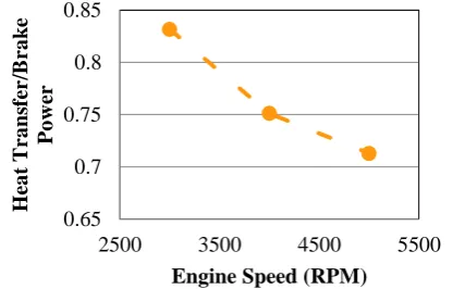
Heat transfer to brake power ratio is one of
the important characteristics in thermal
balance analysis which is experimentally
obtained for studied engine as illustrated in
Fig. 9. More description about this parameter
will be discussed in next sections.
0 2 4 6
2500 3500 4500 5500
B
rake
Pow
e
r (
K
W)
RPM
Numerical Experimental
0 2 4 6 8
2500 3500 4500 5500
Exh
au
st
En
e
rg
y
(K
W)
RPM
Numerical Experimental
0 5 10 15
3000 3500 4000 4500 5000
Dev
ia
tio
n
(%)
Engine Speed (RPM)
Exhaust Temperature Brake Power
2686 International Journal of Automotive Engineering (IJAE) Figure 7: Distribution of Energy in Gasoline Engine as
a Function of Engine Speed
5.2.
Numerical Results
5.2.1. Thermal Balance Analysis
The amount of energy distribution in various engine speeds is demonstrated in Table 2 by increasing engine speed, obviously the amount of exhaust power, brake power and heat transfer increases as illustrated in Fig. 10. The most brake power produced by engine is 5.2 kW which is generated at 6000 rpm. As presented in Fig. 10, heat transfer increases regarding to engine speed increment. Fig. 10 also illustrates that the amount of exhaust lost power in different engine speeds. The most lost exhaust power, 6.9 kW happens at 6000 rpm.
Figure 8: Experimental Total Balance of Gasoline Engine in Various Engine Speeds
Figure 9: Experimental Heat Transfer to Brake Power Ratio
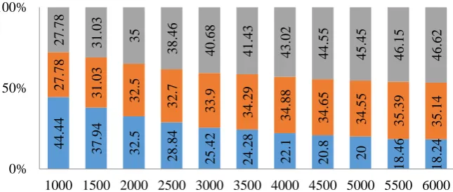
As it is shown in this bar charts, the summation of all energy terms is 100% which equals to total fuel energy. The percentage of each part of energy balance is given on bar charts. As engine speed increases, the percentages of exhaust and brake power rise, while the percentage of heat transfer decreases as illustrated in Fig. 11. In other words, brake power percentage indicates brake thermal efficiency and it increases slightly regarding to engine speed. On the other hand, reduction of heat transfer percentage takes place due to the limited time for heat transfer in high engine speeds. According to thermal balance analysis, as engine speed increases, power losses throughout heat transfer decrease significantly, but the brake power does not increase as expected due to dramatic increase of power carried away by
exhaust.
Table 2. Energy Distribution of Engine in Different Engine Speeds
Energy Distribut
ion
Heat Transfe
r (kW)
Brake Powe
r (kW)
Exhaus t (kW)
Engine Speed (RPM)
1000 0.8 0.5 0.5
1500 1.1 0.9 0.9
2000 1.3 1.3 1.4
2500 1.5 1.7 2
3000 1.5 2 2.4
3500 1.7 2.4 2.9
0 1 2 3 4 5 6 7 8 9 10 11 12
2500 3500 4500 5500
P
o
w
er
(
k
W)
Engine Speed (RPM)
Fuel Energy Exhaust Power
Brake Power Heat Transfer
27.29% 24.97% 23.35% 32.82% 33.23% 32.75% 39.89% 41.8% 43.9%
0% 50% 100%
3000 4000 5000 Engine Speed (RPM)
Exhaust Brake Power Heat Transfer
0.65 0.7 0.75 0.8 0.85
2500 3500 4500 5500
H
ea
t
T
ra
ns
fer
/B
ra
k
e
P
o
w
er
Engine Speed (RPM)
International Journal of Automotive Engineering (IJAE) 2687
4000 1.9 3 3.7
4500 2.1 3.5 4.5
5000 2.2 3.8 5
5500 2.4 4.6 6
6000 2.7 5.2 6.9
Figure 10: Energy Distribution of in Different Engine Speeds
Figure 10: Energy Distribution of in Different Engine Speeds
0 1 2 3 4 5 6 7
1000 2000 3000 4000 5000 6000
E nerg y Dis tributio n (k W)
Engine Speed (RPM)
Heat Transfer Brake Power Exhaust
4 4 .4 4 3 7 .9 4 3 2 .5 2 8 .8 4 2 5 .4 2 2 4 .2 8 2 2 .1 2 0 .8 20 1 8 .4 6 1 8 .2 4 2 7 .7 8 3 1 .0 3 3 2 .5 3 2 .7 3 3 .9 3 4 .2 9 3 4 .8 8 3 4 .6 5 3 4 .5 5 3 5 .3 9 3 5 .1 4 2 7 .7 8 3 1 .0 3 35 3 8 .4 6 4 0 .6 8 4 1 .4 3 4 3 .0 2 4 4 .5 5 4 5 .4 5 4 6 .1 5 4 6 .6 2 0% 50% 100%
1000 1500 2000 2500 3000 3500 4000 4500 5000 5500 6000 Heat Transfer Brake Power Exhaust
2688 International Journal of Automotive Engineering (IJAE)
5.2.2. Heat Transfer and Exhaust Power to
Brake power Ratios
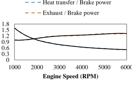
Heat transfer to brake power (HtB) and exhaust power to brake power (EtB) ratios are significant performance characteristics of internal combustion engines. These parameters in various engine speeds are shown in Fig. 12. Increasing engine speed leads to decreasing heat transfer to brake power ratio (HtB). Although both brake power and heat transfer increase with engine speed, brake power growth is more than heat transfer; therefore the fraction will decrease. As engine speed increases, exhaust power to brake power ratio (EtB) increases. Indeed, the growth of exhaust power is more than brake power and the fraction has upward trend.
As a function of engine speed, both specific heat rejection (HtB) and exhaust power to brake power ratio (EtB), are estimated by a fifth-degree polynomial function with different coefficients given by Eq. (19). The coefficients of HtB and EtB correlation are specified in Table 3. The least square related to HtB and EtB are 0.9986 and 0.9817 respectively which shows high accuracy of the fifth-degree polynomial function.
Figure 12: Energy Distribution of in Different Engine Speeds
(19)
Table 3. Coefficients of Heat Transfer and Exhaust Power to Brake Power ratios
Coefficien t
HtB EtB
5.2.3. Brake Specific Fuel Consumption
The specific fuel consumption is a comparative metric for the efficiency of converting the chemical energy of the fuel into work produced by the engine. The brake specific fuel consumption (bsfc) is the fuel flow rate divided by the brake power. Considering same fuel flow rate, the specific fuel consumption and engine efficiency are inversely related; i.e. the lower the specific fuel consumption, the greater the engine efficiency[18]. As shown in Fig. 13, brake specific fuel consumption (bsfc) of gasoline engine decreases until around 3500 rpm and then remains approximately constant.
0 0.3 0.6 0.9 1.2 1.5 1.8
1000 2000 3000 4000 5000 6000
Engine Speed (RPM) Heat transfer / Brake power Exhaust / Brake power
International Journal of Automotive Engineering (IJAE) 2689
Figure 13: Brake Specific Fuel Consumption in Different Engine Speeds
5.2.4. Instantaneous In-Cylinder Energy
Balance
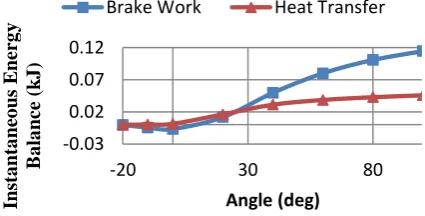
Instantaneous in-cylinder brake work and heat transfer per cycle at 4000 rpm are presented in Fig. 14. As illustrated in Fig. 14, crank angles vary from -20 to 100 degrees which indicates combustion and expansion stroke.
Figure 14: Instantaneous In-Cylinder Energy Balance in Different Crank Angles at 4000 rpm
6.
Conclusions
In this research, the thermal balance analysis of an air-cooled, single cylinder, four-stroke engine is studied experimentally and numerically. In order to carry out experiments, setup is equipped with proper measuring instruments such as K-type thermocouples, data logger, prony brake dynamometer, etc. Experiments are conducted on gasoline engine
in various engine speeds which is used for validation. Then numerical simulation carried out in order to compare efficiency and performance characteristics of the engine. From the results of this study, the following results can be concluded.
It is specified that about one-third of fuel energy is converted to effective power. Major part of total energy is dissipated by exhaust, heat transfer, friction, etc.
It is determined that by increasing engine speed, the amount of brake power, exhaust power, and heat transfer rises. The most output, exhaust power and heat transfer are 5.2 kW, 6.9 kW and 2.7 respectively which are generated at maximum engine tested rpm. Total thermal balance analysis indicates that the percentages of exhaust and brake power rise, while the percentage of heat transfer decreases as engine speed increases. There is a slight increase in brake thermal efficiency with respect to the engine speed increment. As engine speed rises, percentage of heat transfer decreases due to the time limitation.
One of the most significant performance characteristics of internal combustion engines is heat transfer to brake power ratio (HtB) which decreases when engine speed increases. As a function of engine speed, both specific heat rejection (HtB) and exhaust power to brake power ratio (EtB), are estimated by a fifth-degree polynomial function with different coefficients.
Brake specific fuel consumption (bsfc) of gasoline engine decreases until around 3500 rpm and then remains approximately constant.
List of symbols
cylinder pressure, kPa 220
240 260 280 300 320
1000 2000 3000 4000 5000 6000
B
SFC
(g
/k
W
-h)
Engine Speed (RPM)
-0.03 0.02 0.07 0.12
-20 30 80
Ins
ta
nta
neo
us
E
nerg
y
B
a
la
nce
(k
J
)
Angle (deg)
Brake Work Heat Transfer
2690 International Journal of Automotive Engineering (IJAE) crank angle, degree
specific heat ratio mass fraction burned engine’s wall heat loss, J
in-cylinder volume, m3 cylinder clearance volume, m3 cylinder bore, m
connecting rod’s length, m
crank radius, m
distance between piston pin axis and crank axis, m
adjustable parameter adjustable parameter start of combustion, degree heat transfer coefficient, W/m2K temperature, K
average cylinder gas velocity, m/s wall area, m2
wall temperature, K
In-cylinder gas temperature, K constant parameter
̅ mean piston speed, m/s
constant parameter
working-fluid temperature, K working-fluid pressure, kPa working-fluid volume, m3
in-cylinder maximum pressure, kPa motored cylinder pressure, kPa engine speed, rpm
̇ rate of energy, kJ
̇ fuel power, kW
̇ brake power, kW
̇ dissipated power by exhaust, kW ̇ dissipated power by heat transfer, kW
fuel heating value, kJ/kg combustion efficiency ̇ mass flow rate of air, kg/s ̇ mass flow rate of fuel, kg/s
exhaust gases temperature, ambient temperature,
average specific heat of exhaust gases, kJ/kg.K
displacement volume, m3 number of cylinders
brake mean effective pressure, bar indicated mean effective pressure, bar friction mean effective pressure, bar Heat transfer to brake power ratio Exhaust power to brake power ratio
References
[1]. Özcan, H. and M. Söylemez, Thermal balance of a LPG fuelled, four stroke SI engine with water addition. Energy conversion and management, 2006.
47(5): p. 570-581.
[2]. Magno, A., E. Mancaruso, and B.M. Vaglieco, Effects of a biodiesel blend on energy distribution and exhaust emissions of a small CI engine. Energy Conversion and Management, 2015. 96: p. 72-80.
[3]. Yusri, I., et al., Experimental
investigation of combustion, emissions and thermal balance of secondary butyl alcohol-gasoline blends in a spark ignition engine. Energy
International Journal of Automotive Engineering (IJAE) 2691 Conversion and Management, 2016.
123: p. 1-14.
[4]. Khoobbakht, G., et al., Exergy and Energy Analysis of Combustion of Blended Levels of Biodiesel, Ethanol and Diesel Fuel in a DI Diesel
Engine. Applied Thermal Engineering, 2016. 99(Supplement C): p. 720-729. [5]. Duan, X., et al., Experimental study on
the energy flow of a gasoline-powered vehicle under the NEDC of cold starting. Applied Thermal
Engineering, 2017. 115(Supplement C): p. 1173-1186.
[6]. Li, T., J.A. Caton, and T.J. Jacobs, Energy distributions in a diesel engine using low heat rejection (LHR) concepts. Energy Conversion and Management, 2016. 130: p. 14-24. [7]. Ajav, E., B. Singh, and T.
Bhattacharya, Thermal balance of a single cylinder diesel engine operating on alternative fuels. Energy
conversion and management, 2000.
41(14): p. 1533-1541.
[8]. Gharehghani, A., et al., Experimental investigation of thermal balance of a turbocharged SI engine operating on natural gas. Applied Thermal
Engineering, 2013. 60(1): p. 200-207. [9]. Yingjian, L., et al., Energy balance
and efficiency analysis for power generation in internal combustion engine sets using biogas. Sustainable energy technologies and assessments, 2014. 6: p. 25-33.
[10]. Abedin, M., et al., Energy balance of internal combustion engines using alternative fuels. Renewable and Sustainable Energy Reviews, 2013.
26: p. 20-33.
[11]. Payri, F., et al., Experimental analysis of the global energy balance in a DI diesel engine. Applied Thermal Engineering, 2015. 89: p. 545-557. [12]. Durgun, O. and Z. Şahin, Theoretical
investigation of heat balance in direct injection (DI) diesel engines for neat diesel fuel and gasoline fumigation. Energy Conversion and Management, 2009. 50(1): p. 43-51.
[13]. Yüksel, F. and M. Ceviz, Thermal balance of a four stroke SI engine operating on hydrogen as a
supplementary fuel. Energy, 2003.
28(11): p. 1069-1080.
[14]. Taymaz, I., An experimental study of energy balance in low heat rejection diesel engine. Energy, 2006. 31(2): p. 364-371.
[15]. Shojaeefard, M.H., P. Azarikhah, and A. Qasemian, Experimental
Investigation of Thermal Balance and Valve Cover Heat Transfer in a Small Internal Combustion Engine.
International Journal of Automotive Engineering, 2017. 7(2): p. 2423-2433.
[16]. Type K Thermocouple. 2011 [cited 2017 24/11/2017]; Available from: https://www.thermocoupleinfo.com/ty pe-k-thermocouple.htm.
[17]. Heywood, J.B., Internal combustion engine fundamentals. Vol. 930. 1988: Mcgraw-hill New York.
[18]. Ferguson, C.R. and A.T. Kirkpatrick, Internal combustion engines: applied thermosciences. Third ed. 2016: John Wiley & Sons.
[19]. Yun, K.T., et al., Modeling of reciprocating internal combustion engines for power generation and heat recovery. Applied energy, 2013. 102: p. 327-335.
[20]. Horlock, J. and D. Winterbone, The thermodynamics and gas dynamics of internal-combustion engines. . Vol. 2. 1986: New York, NY; Oxford
University Press.