0 INTRODUCTION
The connections between the undercarriage and upper structure in certain types of cranes and earth-moving machines are accomplished by large diameter bearings, considering the influence of various
operational and structural requirements.The purpose
of analysing the functioning of these connections in real conditions is to provide an adequate distribution of loads, as well as the reliable and long-lasting operation of large bearings. The main research topics about large slewing bearings are related to empirical investigations and computational analyses of the failure mechanisms and the determination of internal
contact load distributions and load capacity [1].
Generally, authors use both the analytical and the numerical approach for solving these problems. The detailed review of the former analytical approaches is presented in [2] and [3], where both articles offer the calculation models for determination of the contact angle and the carrying capacity of a four contact-point ball bearing.
Modern approaches for computing the load capacity of slewing bearings are based on the finite element method (FEM). These computational methods ([4] and [5]) include the most influential parameters, such as the raceway/ring deformations, non-parallel ring displacements, and bearing clearances. In general, it has been shown that all of these parameters have a significant role when determining the load capacity
of large slewing bearings. Olave et al. [6] used two
different ways for obtaining the force distribution in four contact-point slewing bearings (FEM analysis and new calculation procedure considering the effect of the structure’s elasticity). This analysis shows that the flexibility of the structures must be taken into account during the calculation of load distribution. Authors in [7] outline a procedure for the determination of the interferences between balls and raceways in four contact-point slewing bearings due to the manufacturing errors. Therefore, an inadequate hardened raceway depth can cause raceway failure. In contrast, an excessively large hardened raceway depth can increase the overall vibration and production cost.
Analysis of the Influence Parameters on the Support
Structure Stiffness of Large Radial-Axial Bearings
Тrifković, S. – Zdravković, N. – Gašić, M. – Savković, M. – Marković, G.
Spasoje Тrifković1 – Nebojša Zdravković2 – Мilomir Gašić2 – Мile Savković2 – Goran Marković2,*
1 University of East Sarajevo, Faculty of Mechanical Engineering, Bosnia and Herzegovina 2 University of Kragujevac, Faculty of Mechanical and Civil Engineering in Kraljevo, Serbia
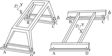
In certain types of crane and earth-moving machinery, such as portal cranes, loaders and excavators, the transfer of loads to crane tracks or the terrain is accomplished by means of undercarriage frames composed of box-like girders. The hypothesis that all four supports of the undercarriage frame do not lie in the horizontal plane is the basis for the formation of a calculation model. This paper analyses the influence of geometric parameters of box-like girders on the magnitude of additional forces at the supports of those frames when one of the supports is raised or lowered relative to the horizontal plane for the size Δ. Theoretical dependences between moments of inertia and stiffness under bending and torsion of those girders were thus established. Obtained relations leads to more concise forms of expressions for influential coefficients in Maxwell-Mohr integrals and simplifies optimization methods in the design of support structures. With experimental verification of the results, the influences of geometric parameters on the stiffness of the support structure are confirmed, and preconditions are created for further analysis of the connection made by large diameter bearings.
Keywords: support structure, large diameter bearing, box-like girders, geometrical parameters, stiffness, experimental verification
Highlights
• A calculation method was created for determination of additional forces in the undercarriage frame supports in relation to its geometric parameters and initiative deflection in one support.
• The dependence between the ratio of moments of inertia for bending and torsion and the height-width ratio of the box-like cross-section was established.
• Dependences were confirmed using the measurement results on the models of undercarriage frames of different geometrical values.
Authors in [8] analysed a three-row roller slewing bearing with a hardened raceway, by using a non-linear spring instead of a solid roller, to quickly obtain the maximum contact load.
Another direction of research leads to the analysis of influences of the undercarriage frame on the slewing bearing operation. Many researchers have found the stiffness of the supporting structure to be a crucial constructional problem of large slewing mechanisms
([9] and [10]). The supporting structure and the
bolted connections cannot be ignored when the load distribution and carrying capacity of a slewing bearing are analysed. The effects of supporting structure, bolts number and preload, ball-race contact truncation and bolt-hole backlash on the carrying capacity of the
slewing bearing are analysed in [11]. Results show
that the fatigue life and carrying capacity of the slewing bearing can be enhanced by appropriately decreasing the supporting structure stiffness. Duval et al. [12] proposed fatigue analysis, taking into account the complex multiaxial stress state and the gradient of material properties, due to the surface treatment of the tracks (induction hardened parts). A method for the fatigue testing of the raceway by using a small sample is presented in [13]. Recent research [14] is directed to additional factors that influence the position of the resultant force exerted by the superstructure on the undercarriage (large excavation or loading forces, the mass of the transported material and ground inclination). Smaller deviations of the centre of the gravity accelerate the wear of the bearing raceway and cause overloading of the bolts that connect the bearing to the supporting elements. For that purpose, the experimental determination of the centre of the gravity of opencast mining machines is presented in
[15].
There are not many publications describing the influences of geometrical parameters of the large diameter bearing support structure on its stiffness. Namely, the clearance between one of the undercarriage frame supports and the crane track or the terrain may occur. Hence, the problem of missing contact can appear due to irregularities on the base or, more rarely, errors that arise during manufacturing. As a consequence, there is a redistribution of vertical forces at the supports and the deformation of the carrying structure during exploitation.
In this paper, attention is directed to the creation of a calculation model, used to define theoretical dependences between the geometrical parameters of box-like girders and the magnitude of additional forces at the undercarriage frame supports. Specifically, the magnitude of additional forces directly influences the
functioning of large diameter bearings. The research of those relations was carried out to define such stiffness that the deformation of the support surface of the bearing would not exceed recommended values. Along with the experimental verification of the obtained theoretical results, the preconditions for significant simplification of some optimization methods [16] in the design of carrying structures with box-like girders were established.
After the introductory notes and the overview of previous investigations, the calculation model of the undercarriage frame is presented. The next section deals with the box-like section with constant thickness. Firstly, after some approximations, the theoretical dependence between the ratio of bending and torsional stiffness and the height-width ratio of the section is defined. Consequently, after solving the canonical equations and by using MATLAB curve-fitting tools, the influences of change in girders’ height-width ratios and change of structure lengths on the additional forces are determined. After this, an experimental verification on a laboratory model of the undercarriage frame is presented. The conclusion section gives the final remarks and the directions for further research.
1 CREATION OF THE CALCULATION MODEL
In the carrying structures of loader bridges,
portal cranes and excavators, clearance ∆ may occur
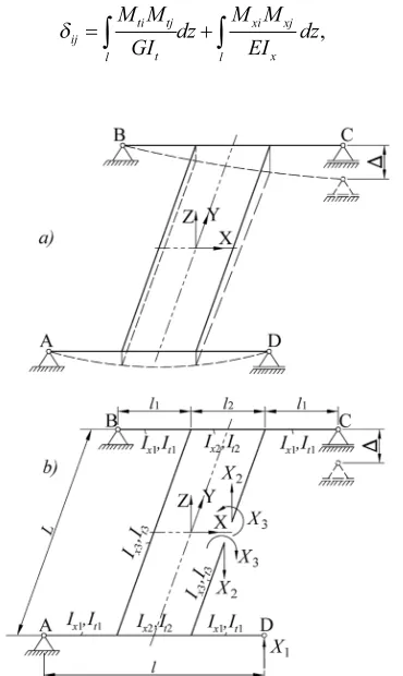
under one of the supports of undercarriage frames (e.g., under the support C) in relation to the crane track or terrain (Fig. 1). The basic calculation model obtains the form as in Fig. 2b, where we take the reactions X1
as the force redundant at D and redundant reactions X2
and X3by cutting the structure at an arbitrary interior
point. The flexibility coefficients are now interpreted as the relative displacements of the adjacent cross-section.
The resulting displacements of the primary structure due to the external loading and redundant reactions are expressed as:
δij j i
j X i
+ = =
=
∑
∆ 0 1 2 31 3
, , , , (1)
where δij is the flexibility coefficients, Xj the unknown forces and moment, Δi the displacement at i due to the external loading in the direction of the restraint at i.
The flexibility coefficients δij are determined by the Maxwell-Mohr integral [17]:
δij ti tj t l xi xj x l yi yj y l i j l M M GI dz M M EI dz M M EI dz N N EA dz = + + + + +
∫
∫
∫
∫
KK Q QGA dz K Q QGA dz
x xi xj
l
y yi yj
l
∫
+∫
. (2)For the considered case (no axial forces nor horizontal bending, the influence of shear forces is neglected), δij has the form:
δij ti tj t l xi xj x l M M GI dz M M EI dz
=
∫
+∫
, (3)Fig. 2. Schematic presentation of the undercarriage frame: a) position of the undercarriage frame with the clearance
∆ at the support C; b) calculation model of the frame with the unknowns X1, X2 and X3
Integration over the entire contour results in:
δ δ 11 1 3 1 1 2 2 2
1 2 2 1
2 2 2 22 2 3 4
3 2 1 3
2 3 = +
(
+ +)
+ = l EI l lEI l l l l
l L GI l
E
x x t
, II L EI l L GI
x2 x t
3 3 2 2 2 6 2 + + ,
(4)δ δ
δ 33 2 2 3 12 2 2 1 2 2 13
2 1 2
2 2 3 2
3 2 = + =
(
+)
= −(
+)
l EI L GIl l l
EI
l l l
EI
x t x
, ,
xx t x
l L GI l EI 2 2 3 23 2 2 2 − , δ = − ,
As can be seen from Eq. (4), bending stiffness (EI) and torsional stiffness (GIt) figure in some of them. By establishing the theoretical dependence between them, Eq. (4) would obtain a more concise form, which would simplify the analysis below.
2 THEORETICAL DEPENDENCE OF THE RATIO OF BENDING AND TORSIONAL STIFFNESS
OF BOX-LIKE GIRDERS
The moment of inertia of the box-like cross-section (Fig. 3) with constant thicknesses of horizontal and vertical plates δ, for the axis x, is defined by the expression:
Ix= h b b h
+
(
)
+(
−)
+(
−)
212 2 12 4
3 3 2
δ δ δ δ
δ δ . (5)
Fig. 3. Section of the box-like girder with constant plate thickness
Further, if the height of the box-like girder h is expressed through the width b, i.e., if the coefficient
k = h / b is introduced, by neglecting the members in
which δ3and δ4(δ <<b; δ <<h), then the expression
for the moment of inertia of the cross-section of the box-like girder Eq. (5) can be written in the form:
Ix' =k b k( + ).
2 3
6 3
Since the thicknesses of the plates are equal, the torsional moment of inertia can be written in the following form:
I b h
b h
k b k
t = + = +
2 2
1 2 2δ2 2 3
δ δ
δ
. (7)
Now, the following relation can be formed: I
I i
k k
x
t
' '
. = = 2+4 +3
12 (8)
The same relation with the exact value for Ix (Eq. (5)) is designated as i = Ix / It. Eq. (8) has a parabola shape. Since the real values for k are within the interval between 1 and 3, it can be approximated with a linear polynomial which gives the lowest deviations. This was obtained with the MATLAB software package and its incorporated tools for approximation. A set of arranged pairs (k, i) is defined with a step 0.5 for k (Table 1). For the given first degree of the polynomial, the following is obtained:
i i k=
( )
=0 667. k−0 048. . (9)The relative deviations at the corresponding points during the approximation by a first degree polynomial are also given in Table 1.
Table 1. Set of arranged pairs(k, i)
Reference point k i = i(k) Approximation error [%]
1 1.0 0.667 −6.291
2 1.5 0.937 1.481
3 2.0 1.250 2.778
4 2.5 1.604 0.866
5 3.0 2.00 −2.430
By neglecting the free member due to its small value, Eq. (9) obtains the following form:
i i k=
( )
≈2k3 . (10)
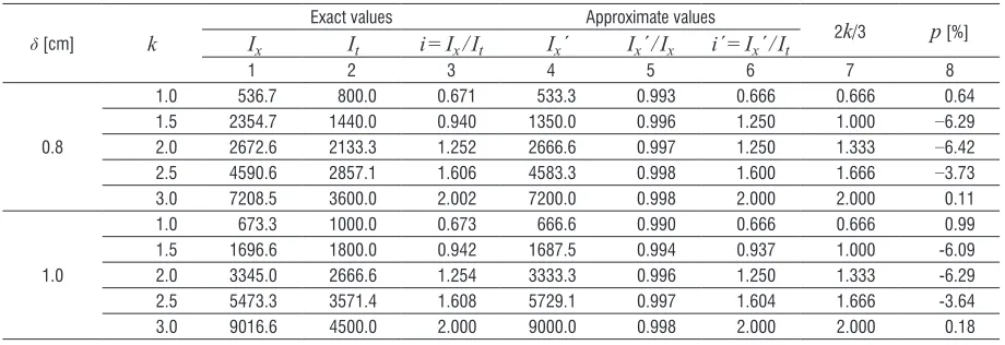
The relative error made by this transformation does not exceed 6.5 %. The approximation is confirmed for the cross section of the real box-like girders with characteristics: b = 30 cm; δ = 0.8 cmand 1.0 cm and k = 1.0, 1.5, 2.0, 2.5, 3.0(Table 2).
It can be shown that even for larger plate thicknesses (over 1 cm), the percentage deviation from exact values of the ratio does not exceed 8 %. By analysing the values from Table 2, it can be concluded that the approximation is acceptable not only for practical but also for theoretical usage.
Regarding the theoretical dependence (Eq. (10)), it is also possible to establish the approximate
dependence between bending stiffness (EIx) and
torsional stiffness (GIt) of the box-like girder: EI
GI
GI GI
I
I k
x
t
x
t
x
t
=2 1
(
+ν)
=2 1 0 3(
+ .)
≈ 3 . (11)The defined ratio of the bending stiffness and the torsional stiffness of box-like girders (Eq. (11)) is important for the optimization of the crane and earth-moving machinery carrying structures. It enables creating the compact analytical models, suitable for application of the optimization methods, which provide the solution with increased bending and torsional stiffness, along with the mass reduction.
2.1 Additional Forces at the Supports of Undercarriage Frames
The solution of the canonical equations (Eq. (1)) contains the value of the additional force X1 at support
D, caused by the lowering of the support C by a value
∆ (Fig. 2).
Table 2. Exact and approximate ratio values
δ [cm] k
Exact values Approximate values
2k/3 p [%]
Ix It i = Ix / It Ix´ Ix´ / Ix i´ = Ix´ / It
1 2 3 4 5 6 7 8
0.8
1.0 536.7 800.0 0.671 533.3 0.993 0.666 0.666 0.64
1.5 2354.7 1440.0 0.940 1350.0 0.996 1.250 1.000 −6.29
2.0 2672.6 2133.3 1.252 2666.6 0.997 1.250 1.333 −6.42
2.5 4590.6 2857.1 1.606 4583.3 0.998 1.600 1.666 −3.73
3.0 7208.5 3600.0 2.002 7200.0 0.998 2.000 2.000 0.11
1.0
1.0 673.3 1000.0 0.673 666.6 0.990 0.666 0.666 0.99
1.5 1696.6 1800.0 0.942 1687.5 0.994 0.937 1.000 -6.09
2.0 3345.0 2666.6 1.254 3333.3 0.996 1.250 1.333 -6.29
2.5 5473.3 3571.4 1.608 5729.1 0.997 1.604 1.666 -3.64
At the same time, due to the symmetry, the reactions at the supports A and C will be decreased by the same value X1.
In real structures, girders 1 and 2 (Fig. 2) are identical, i.e., Ix1 = Ix2, It1 = It2. Further on, the bending
moment of inertia of the girder 3 can be expressed in relation to the bending moment of inertia of the girder 2 by coefficient ε: Ix3 = ε Ix2. Considering Eq. (10) and
the same value of parameter k for the whole structure, it is also It3 = ε It2.
Considering Eq. (11) and having in mind that Δ1 = −Δ and Δ2 = Δ3 = 0, the canonical Eqs. (1) obtain
the following form:
4
3 2 1 3 3
3 1 3 1 2 2 1 2 2 1 2 2 1 2 2 2
l l l l
l l
l l L k X EI l l x + + + + ∆ +
+ ( 11 2 2 2
2 1 2
2 3 2 2 3 2 3 1 + ∆ − + + ∆ = l X
EI l l l
l Lk X EI
x x
)
( ) ,
ε
l l l X
EI
l L l L k X
EI
x x
2 2
1 2 1
2 2 3 3 2 2 2 2 3 2 3 2 3 6 3 2 ( + ) ∆ + + + ∆ ε −−
− ∆l X =
EIx 2 2 3 2 0, (12)
l l l l Lk X
EI l
X EI
l Lk
x x
2 1 2
2 1 2 2 2 2 2 2 2 3
2 2 3 ( + )+ ∆ − ∆ + + + ε ε ∆EIXx =
3
2 0,
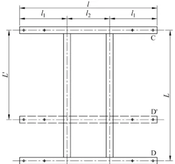
The further analysis is carried out for the real undercarriage frame structures (Fig. 4), with
changeable lengths (L = 4.0 m, 4,5 m, 5.0 m, 5.5 m,
6.0 m) and values of coefficients ε (1.0, 1.5, 2.0) and k (range between 1 and 3).
Fig. 4. Geometrical parameters of undercarriage frames
Solving of Eqs. (12) leads to the values of additional forces X1( j) and X1(i), whose ratio will
be investigated due to the change of length L and
mentioned parameters.
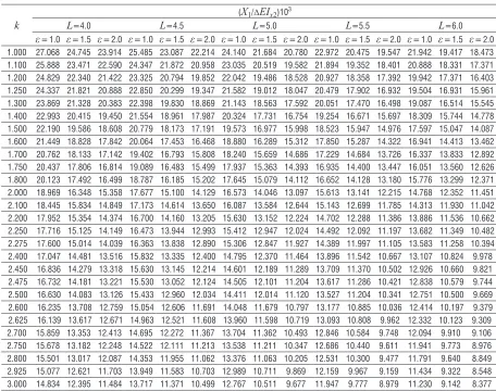
Calculated solutions of Eqs. (12) for all cases are given in Table 3 in the form (X1 / ΔEIx2)103,
based on which the further numerical analyses are conducted. Firstly, the results shown in Table 3 are used to establish the dependence of ratio X1( j) / X1(i) as
a function of the ratio kj/ki, and secondly to establish dependence of ratio X1( j) / X1(i) as a function of the
ratio of the length Li/Lj.
Within the investigation with changeable k, the
ratio between additional force reactions for arbitrary cases j and i, regarding Eq. (6), is calculated as:
X X X k X k X EI k X EI j i j i j
x j tab
i x 1 1 1 1 1 2 1 ( ) ( ) ( ) ( ) ( ) =
( )
( )
= ∆∆ 22
2 2 3 3 ( ) ( ) ( ). k k k k k i tab j j i i ⋅ +
+ (13)
For the second analysis with changeable length, there was no need for such conversion since coefficient k is the same for cases j and i, so the ratio of forces is calculated only by the values from Table 3.
After numerical analysis conducted in MATLAB software and its curve fitting tools, with the neglected influence of coefficient ε, the following dependences were established: X X k k j i j i 1 1 3 ( ) ( ) . ≈
(14)
X X X L X L L L j i j i i j 1 1 1 1 0 6739 ( ) ( ) . ( ) ( ) . = ≈
(15)
3 EXPERIMENTAL ANALYSIS
Experimental analysis was carried out in the laboratory of the Centre for Construction and Transportation Machinery at the Faculty of Mechanical and Civil Engineering in Kraljevo, Serbia. The primary measurements in the experiment were the additional forces at the support D at different deflections ∆ at the support C, for two undercarriage frame models (Fig. 4). All activities during the test should be in the field of elastic material behaviour.
3.1 Object of Testing
The testing models of undercarriage frames consist of square pipes of the unique wall thickness of 2.8 mm,
× h = 60 mm × 120 mm. The dimensions of the tested models (1200 mm × 1200 mm and 1200 mm × 800 mm) are approximately five times smaller than those in real undercarriage frames.
3.2 Test Stand
To carry out the experiment, it was necessary to make a rigid platform (2) (Fig. 5), to which the undercarriage frame (1) is attached. The drilled holes (Ø26 mm) are used for supporting the support brackets (3) and dynamometer (5). Forces at the support D are measured by a dynamometer, due to a deflection at the support C which is set by the presser with a screwed spindle (4). The values of deflection (displacement) at the support C are measured with a comparator (6). Possible height deviations of the upper surfaces of the longitudinal and cross girders can be cancelled by means of the support brackets, which have the
possibility of adjusting the upper surfaces of the supporting frames, so that they lie in the horizontal plane. It should be noted that normal, hot-rolled UNP-100 profiles were used for longitudinal and cross
girders in acc. to EN 10025:2005 [18].
Fig. 5. Connection between the undercarriage frame model (1) and the rigid platform (2)
Table 3. Solutions of canonical Eqs. (12) for different parameters
k
(X1/ΔEIx2)103
L=4.0 L=4.5 L=5.0 L=5.5 L=6.0
ε = 1.0 ε = 1.5 ε = 2.0 ε = 1.0 ε = 1.5 ε = 2.0 ε = 1.0 ε = 1.5 ε = 2.0 ε = 1.0 ε = 1.5 ε = 2.0 ε = 1.0 ε = 1.5 ε = 2.0
1.000 27.068 24.745 23.914 25.485 23.087 22.214 24.140 21.684 20.780 22.972 20.475 19.547 21.942 19.417 18.473 1.100 25.888 23.471 22.590 24.347 21.872 20.958 23.035 20.519 19.582 21.894 19.352 18.401 20.888 18.331 17.371 1.200 24.829 22.340 21.422 23.325 20.794 19.852 22.042 19.486 18.528 20.927 18.358 17.392 19.942 17.371 16.403 1.250 24.337 21.821 20.888 22.850 20.299 19.347 21.582 19.012 18.047 20.479 17.902 16.932 19.504 16.931 15.961 1.300 23.869 21.328 20.383 22.398 19.830 18.869 21.143 18.563 17.592 20.051 17.470 16.498 19.087 16.514 15.545 1.400 22.993 20.415 19.450 21.554 18.961 17.987 20.324 17.731 16.754 19.254 16.671 15.697 18.309 15.744 14.778 1.500 22.190 19.586 18.608 20.779 18.173 17.191 19.573 16.977 15.998 18.523 15.947 14.976 17.597 15.047 14.087 1.600 21.449 18.828 17.842 20.064 17.453 16.468 18.880 16.289 15.312 17.850 15.287 14.322 16.941 14.413 13.462 1.700 20.762 18.133 17.142 19.402 16.793 15.808 18.240 15.659 14.686 17.229 14.684 13.726 16.337 13.833 12.892 1.750 20.437 17.806 16.814 19.089 16.483 15.499 17.937 15.363 14.393 16.935 14.400 13.447 16.051 13.560 12.626 1.800 20.123 17.492 16.499 18.787 16.185 15.202 17.645 15.079 14.112 16.652 14.128 13.180 15.776 13.299 12.371 2.000 18.969 16.348 15.358 17.677 15.100 14.129 16.573 14.046 13.097 15.613 13.141 12.215 14.768 12.352 11.451 2.100 18.445 15.834 14.849 17.173 14.614 13.650 16.087 13.584 12.644 15.143 12.699 11.785 14.313 11.930 11.042 2.200 17.952 15.354 14.374 16.700 14.160 13.205 15.630 13.152 12.224 14.702 12.288 11.386 13.886 11.536 10.662 2.250 17.716 15.125 14.149 16.473 13.944 12.993 15.412 12.947 12.024 14.492 12.092 11.197 13.682 11.349 10.482 2.275 17.600 15.014 14.039 16.363 13.838 12.890 15.306 12.847 11.927 14.389 11.997 11.105 13.583 11.258 10.394 2.400 17.047 14.481 13.516 15.832 13.335 12.400 14.795 12.370 11.464 13.896 11.542 10.667 13.107 10.824 9.978 2.450 16.836 14.279 13.318 15.630 13.145 12.214 14.601 12.189 11.289 13.709 11.370 10.502 12.926 10.660 9.821 2.475 16.732 14.181 13.221 15.530 13.052 12.124 14.505 12.101 11.204 13.617 11.286 10.421 12.838 10.579 9.744 2.500 16.630 14.083 13.126 15.433 12.960 12.034 14.411 12.014 11.120 13.527 11.204 10.341 12.751 10.500 9.669 2.600 16.235 13.708 12.759 15.054 12.606 11.691 14.048 11.679 10.797 13.177 10.885 10.036 12.414 10.197 9.379 2.625 16.139 13.617 12.671 14.963 12.521 11.608 13.960 11.598 10.719 13.093 10.808 9.962 12.332 10.123 9.309
2.700 15.859 13.353 12.413 14.695 12.272 11.367 13.704 11.362 10.493 12.846 10.584 9.748 12.094 9.910 9.106
2.750 15.678 13.182 12.248 14.522 12.111 11.213 13.538 11.211 10.347 12.686 10.440 9.611 11.941 9.773 8.976
2.800 15.501 13.017 12.087 14.353 11.955 11.062 13.376 11.063 10.205 12.531 10.300 9.477 11.791 9.640 8.849
2.925 15.077 12.621 11.703 13.949 11.583 10.703 12.989 10.711 9.869 12.159 9.967 9.159 11.434 9.322 8.548
The undercarriage frame supports (Fig. 6a) are designed in such a way as to provide turning of the frame ends, thanks to the extension (3) in the shape of a ball. The body (1) with the nuts (4) is firmly attached to the rigid platform (5). The nuts have the role of levelling the upper surface of the undercarriage frame. The separation of the ball rod from the body of the ball-like support (1) is prevented by a conical sleeve (2).
The support C (Fig. 6b) is compiled of two girders (3) with an upper (1) and a lower traverse (2), thus making a closed type frame. The upper traverse in its middle part has a bushing with a thread, and the presser with a small pitch thread passes through it. By turning the presser (4), via the pad (10), the end of the undercarriage frame (9) at point C is lowered by a given value of clearance ∆.
The lower traverse of the closed frame (2) has an opening for a permanent joint with the rigid platform by means of the threated rod (5), the washer (6) and the nut (7), which, on its upper part, has a drilled hole which serves as the seat of the device (8) for measuring displacements.
Fig. 6. Ball-like support of the undercarriage frame and the presser with a screwed spindle
3.3 Testing Procedures
Registration of force at the support is provided using the force transducer 5, Flintec RC3D30 (with a capacity of 300 kN and sensitivity 2 %) and alphanumeric display 10 (Fig. 7). Displacement of the girder is registered by the standard dial indicator Mitutoyo 2046SB (range 10 mm, accuracy ±13
µm, graduation ±0.01 mm). To obtain accurate
measurement results, the testing of the elastic material behaviour of the model and calibration procedure of dial indicator are performed. The girder is exposed by setting the displacement of the support C, which is entered manually for 3 mm. The procedure is repeated several times after which the girder is completely unloaded. That displacement which acts on the force converter, whose intensity is read on the alphanumeric display.
All mentioned activities show that a model of undercarriage frame exhibits elastic material behaviour. Displacements ∆C (deflection at the support C) were set with a step of 0.5 mm. Measurements were performed on the four models of undercarriage frames:
1. l × L = 1200 mm × 1200 mm, l2 = 400 mm,
b × h × δ = 60 mm × 60 mm × 2.8 mm (k = 1)
2. l × L = 1200 mm × 1200 mm, l2 = 400 mm,
b × h × δ = 60 mm × 120 mm × 2.8 mm (k = 2)
3. l × L = 1200 mm × 800 mm, l2 = 400 mm,
b × h × δ = 60 mm × 60 mm × 2.8 mm (k = 1) 4. l × L = 1200 mm × 800 mm, l2 = 400 mm,
b × h × δ = 60 mm × 120 mm × 2.8 mm (k = 2)
Fig. 7. Test stand: 1 frame model, 2 rigid platform, 3 ball-like support, 4 presser; 5 force transducer,
6 to 10 comparator; 11 alphanumeric display
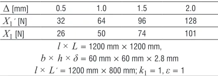
3.4 Measurement Results
The measured values of force X1 at the support D for
all four tested models are shown in Table 4. These measurements were taken for the stepped deflection in
support C (∆= 0.5 mm, 1.0 mm, 1.5 mm and 2.0 mm).
Table 4. Values of additional force at the supports D for test models with k = 1
Δ [mm] 0.5 1.0 1.5 2.0
X1´ [N] 32 64 96 128
X1 [N] 26 50 74 101
l × L = 1200 mm × 1200 mm, b × h × δ = 60 mm × 60 mm × 2.8 mm l × L´ = 1200 mm × 800 mm; k1 = 1, ε = 1
Table 5. Values of additional force at the supports D for test models with k = 2
Δ [mm] 0.5 1.0 1.5 2.0
X1´ [N] 110 224 325 431
X1 [N] 85 172 249 350
l × L = 1200 mm × 1200 mm, b × h × δ = 60 mm × 120 mm × 2.8 mm l × L´ = 1200 mm × 800 mm; k2 = 2, ε=1
The analysis of the measurement results presented in Tables 4 and 5 provides the following dependences: • The ratio of the additional forces X1´ / X1 at the
support D, during the change of the coefficient k (k1 = 1 and k2 = 2), for both values of length
is within the range between 3.27 and 3.50; the calculation result of the obtained theoretical dependence from Eq. (14) is 3.32.
• The ratio of the additional forces X1´ / X at the
support D, during the change of distance L = 1200
mm to L´ = 800 mm, for both values of parameter
k is within the range between 1.23 and 1.31; the calculation result of the obtained theoretical dependence from Eq. (15) is 1.31.
The differences between the numerical and experimental results are less than 6 %. These differences relate to the approximation of moments of inertia and neglecting the influence of the coefficient
ε.
4 CONCLUSION
The theoretical and experimental analysis of the influences of geometrical parameters on the value of additional forces at the supports of undercarriage frames indicates the following conclusions:
• The ratio between the bending moment of inertia and the torsional moment of inertia of the box-like section with unique plate thickness depends on the height/width ratio k as defined in Eq. (10). • As a consequence of the aforementioned, the ratio
of bending stiffness and torsional stiffness can be defined by Eq. (11).
• The relation between the force ratio X1( j) / X1(i)
and the change of height/width coefficient ratio kj/ki is defined by Eq. (14).
• The relation between the force ratio X1( j) / X1(i)
and the change of length ratio Li / Lj is defined by Eq. (15).
The relative error of mentioned approximations does not exceed 6 % in comparison to test results.
The results of the research considerably simplify optimization methods in the design of carrying structures with box-like girders and make the precondition for further investigation of their influence on the functioning of large diameter bearing.
5 ACKNOWLEDGEMENTS
A part of this research is a contribution to the project TR 35038 funded by the Ministry of Education, Science and Technological Development of the Republic of Serbia.
6 REFERENCES
[1] Göncz, P., Potočnik, R., Glodež, S. (2013). Computational model
for determination of static load capacity of three-row slewing bearings with arbitrary clearances and predefined raceway
deformations. International Journal of Mechanical Science,
vol. 73, p. 82-92, DOI:10.1016/j.ijmecsci.2013.04.012.
[2] Zupan, S., Prebil, I. (2001). Carrying angle and carrying
capacity of a large single row ball bearing as a function of geometry parameters of rolling contact and supporting
structure stiffness. Mechanism and Machine Theory, vol. 36,
no. 10, p. 1087-1103, DOI:10.1016/S0094-114X(01)00044-1.
[3] Amasorrain, J.I., Sagartzazu, X., Damián, J. (2003). Load
distribution in a four contact-point slewing bearing.
Mechanism and Machine Theory, vol. 38, no. 6, p. 479-496,
DOI:10.1016/S0094-114X(03)00003-X.
[4] Kania, L., Pytlarz, R., Śpiewak, S. (2018). Modification of
the raceway profile of a single-row ball slewing bearing.
Mechanism and Machine Theory, vol. 128, p. 1-15,
DOI:10.1016/j.mechmachtheory.2018.05.009.
[5] Deng, B., Guo, Y., Zhang, A., Tang, S. (2017). Finite element
analysis of thrust angle contact ball slewing bearing. IOP
Conference Series: Materials Science and Engineering,
vol. 274, art. id. 012096, p. 1-6,
DOI:10.1088/1757-899X/274/1/012096.
[6] Olave, M., Sagartzazu, X., Damian, J., Serna, A. (2010).
load distribution procedure to account for structural
stiffness. Journal of Mechanical Design, vol. 132, no. 2,
DOI:10.1115/1.4000834.
[7] Heras, I., Aguirrebeitia, J., Abasolo, M. (2017). Friction
torque in four contact point slewing bearings: Effect of
manufacturing errors and ring stiffness. Mechanism and
Machine Theory, vol. 112, p. 145-154, DOI:10.1016/j.
mechmachtheory.2017.02.009.
[8] He, P., Liu, R., Hong, R., Wang, H., Yang, G., Lu, C. (2018).
Hardened raceway calculation analysis of a three-row roller
slewing bearing. International Journal of Mechanical Sciences,
vol. 137, p. 133-144, DOI:10.1016/j.ijmecsci.2018.01.021.
[9] Smolnicki, T., Stanco, M., Pietrusiak, D. (2013). Distribution
of loads in the large size bearing-problems of identification.
Tehnički vjesnik - Technical Gazette, vol. 20, no. 5, p. 831-836.
[10] Jerman, B., Hladnik, J., Resman, F., Landschützer, C. (2018).
Optimization of the support structure of large axial-radial
bearing of overhead type manipulator. FME Transactions, vol.
46, no. 3, pp. 386-391, DOI:10.5937/fmet1803386J.
[11] Chen, G., Wang, C., Xiao, Z. (2016). Effects of supporting
Structure and bolt connection on the fatigue life and carrying
capacity of a slewing bearing. Proceedings of the Institution of
Mechanical Engineers, Part J: Journal of Engineering Tribology,
vol. 231, no. 6, p. 1-17, DOI:10.1177/1350650116677606.
[12] Duval, R., Bannebach, J., Blasiak, J., Guelbi, A. (2018).
Modelling fatigue behavior of slewing rings in crane structures.
Identification of influencing parameters on local stresses and
fatigue damage calculations. Procedia Engineering, vol. 213,
p. 323-334, DOI:10.1016/j.proeng.2018.02.033.
[13] He, P., Hong, R., Wang, H., Lu, C. (2018). Fatigue life
analysis of slewing bearings in wind turbines. International
Journal of Fatigue, vol. 111, p. 233-242, DOI:10.1016/j. ijfatigue.2018.02.024.
[14] Pietrusiak, D., Smolnicki, T., Stanńco, M. (2017). The influence
of superstructure vibrations on operational loads in the
undercarriage of bulk material handling machine. Archives of
Civil and Mechanical Engineering, vol. 17, no. 4, p. 855-862,
DOI:10.1016/j.acme.2017.03.001.
[15] Maslak, P., Przybylek, G., Smolnicki, T. (2017). Comparison of
selected methods for the determination of the center of gravity
in surface mining machines. Materials Today: Proceedings,
vol. 4, no. 5, p. 5877-5882, DOI:10.1016/j.matpr.2017.06.062.
[16] Gašić, М., Savković, M., Bulatović, R. (2011). Optimization
of trapezoidal cross section of the truck crane boom by Lagrange’s multipliers and by differential evolution algorithm
(DE). Strojniški vestnik - Journal of Mechanical Engineering,
vol. 57, no. 4, p. 304-312, DOI:10.5545/sv-jme.2008.029.
[17] Karnovsky, I.A., Lebed, O. (2010). Advanced Methods of
Structural Analysis, Springer New York, London.
[18] EN 10025:2005. Hot Rolled Products of Structural Steels - Part
1: General Technical Delivery Conditions. European Committee