of a Powder Forged Connecting rod
E. Honarvar Gheysari
1*, A. Babakhani,
1, A. Haerian,
21. Department of Metallurgical and Materials Engineering, Faculty of Engineering, Ferdousi University of Mashhad, Mashhad, Iran 2. Industrial University of Sajjad, Mashhad, Iran
Abstract
Shot peening applies a residual compressive stress field (RCSF) on the surface of parts. It also shifts “crack nucleation sites” to sub-surface locations. A nondestructive method of measuring the stresses, Sin2ψ was utilized here and the stress values introduced to Ansys software. For this purpose, uniform stress in all directions was applied on the con rod. Loading on the rod in Ansys had three steps: RCSF caused by shot peening (measured by XRD), and tensile and compressive stresses caused by inertial and gas forces, respectively (calculated). Fatigue Macro of Ansys was resumed carrying out the cyclic loading and thereby, improvement of powder forged connecting rods' fatigue life, caused by shot peening was obtained.
Keywords: Fatigue Life, Shot peening, X-ray Diffraction, Ansys.
1. Introduction
Highly cyclic loaded automobile parts such as connecting rods need to have high mechanical properties, especially fatigue – promotions. There are many methods for improving fatigue behavior of such parts, including shot peening, laser shock processing methods [1], ultrasonic peening [2, 3], coatings [4], surface densification and surface rolling [5]. All of the above mentioned methods have the common characteristics of applying residual compressive stress field (RCSF) on the surface of the part. Among these methods, shot peening is the most frequently used method. This method is based on inducing minor plastic deformations on the surface of the part. It produces a surface layer of compressive stresses and modifies fatigue behavior of many industrial parts and materials [6, 7 and 8].
Shot peening assures satisfactory fatigue life and reliability of the automotive, aerospace and marine components and is a very important step in manufacturing of critical automobile parts such as connecting rods. E.Illia and K.Totten [9] investigated effects of different shot peening intensities on the improvement of fatigue life and strength of an automobile connecting rod. They showed that because of the plastic deformation caused by energy of the
shots, fatigue crack nucleation sites shift to sub-surface locations and higher stresses.
C.M. Sonsino [10] divided structural durability parameters into four aspects of fatigue, impact, creep and wear. For the analysis of highly fatigue loaded parts such as connecting rods, synchronizer hubs and gear wheels, extensive data required, such as loading mode (axial, bending, torsion, rolling contact, constant and variable amplitude, mean stress effects, sliding) and geometry (notch and loading mode dependent stress concentration) was collected by the author.
There are many destructive and nondestructive methods such as hole drilling and X-ray diffraction (XRD) techniques to measure RCSF. G. Johnson [11] compared different destructive and nondestructive methods of quantifying RCSF and also measured stresses induced by laser shock peening and the stress present in linear friction welds as well as „stress-relief' occurring in cryogenic aluminum plates.
In the XRD method, since the depth of penetration of the x-ray beam is extremely shallow, the diffracting volume can be considered to represent a free surface under plane stress. As shown in Fig. 1, the biaxial surface stress field can be defined by the principal residual and/or applied stresses (σ1 and σ2), with no stress normal to the surface. The stress to be determined is σφ, lying in the plane of the surface at an angle of φ to the maximum principal stress, σ1.
The direction of measurement is determined by the plane of diffraction. The stress in any direction (for any angle, φ) can be determined by rotating the specimen in the x-ray beam. If the stress is measured in at least three different directions, the principal stresses and their orientations can be calculated. This method is based on measuring an angle ψ, hence known as Sin2ψ method. It is supposed that plastic strains caused by shot impingements change the distances between atomic planes (d) which can be measured by XRD. By plotting atomic plane distances (d) versusSin2ψ and measuring the slope of the achieved line, σφ is easily calculated by a simple formula [12].
Finite element method (FEM) is an approach for fatigue life analysis and estimation of the component longevity. It gives the stress/strain distribution throughout the whole component, which leads to pinpointing critical points authentically. This technique seems quite useful particularly when the component does not have a simple geometry, or the loading conditions are sophisticated which brings out easy and quick component optimization against fatigue failure. Analysis is performed in a virtual environment without any necessity for prototype construction, saving time and cost [13].
Mirehei et.al.[14] studied fatigue behavior of U650 tractor connecting rod through (FEM) using Ansys software. They found the most critical nodes and the number of allowable force exertion cycles with the totally reverse loading which increased by decreasing the stress concentration factor.
P.S. Shenoy and A.Fatemi [15] carried out dynamic load analysis of a connecting rod and utilized finite element modeling to optimize applied loads and allowable stresses of a forged steel connecting rod. Using FEM, weight and manufacturing cost was modified. This has entailed
performing a detailed dynamic load and quasi-dynamic stress analysis.
In the present paper positive feedback of shot peening on fatigue life of a powder forged connecting rod for a Pride car (KIA Motors), is demonstrated. The paper is organized as follows:
1 – Preparation and shot peening of Almen strips and connecting rods.
2 – Measurement of shot peening induced RCSF by XRD, according to Sin2ψ method.
3 –Material characterization, load analysis of con rod and calculation of inertial and gas forces.
4- Computer model preparation and meshing and identification of constraints.
5- Three-step loading (RCSF applying, tensional and compressive caused by inertial and gas forces).
6- Cyclic loading and final analysis.
7- Comparison of simulation results with real condition fatigue test results of powder forged (Fe Cu C) connecting rods.
2. Experimental and Simulation Procedure
2.1. Sample Preparation and Shot peening
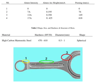
Fe Cu C (iron powder containing 0.6% C and 2% Cu) is one of the most common powders used for powder forging of connecting rods. Powder forging of the rods was carried out in MPF Company, Mashad. In order to measure the shot intensity, the standard Almen strips from Electronics Incorporations were fastened on an appropriate fixture, and sent to the spiral type peening machine along with the rods. Shot peening was carried out according to SAE J443 [16]. Peening time, Almen arc height and intensities are summarized in Table1. Characteristics of the shots, such as size, shape, hardness and the structure are listed in Table 2.
Fig1..Plane stress in a free surface [12].
Table 1. Peening time, Almen Intensity & Arc Height of Strips.
Peening time(s) Almen Arc Height(mm)A
Almen Intensity N0.
0 0
0 1
76 0.195
7A 2
149 0.350
13A 3
618 0. 425
17A 4
Table 2 Shape, Size, and Hardness & Structure of Shots.
Shape Diameter(mm)
Hardness(HV30) Material
Spherical 0.5 - 1
470 - 610 High Carbon Martensitic Steel
Fig2.Three regions to look for answer convergence.
2.2. Finite Element Analysis
2.2.1. Model Preparation and Meshing
To prepare a suitable model and to simplify the case, bolts and bearings were omitted from the connecting rod solid model. Lower half piece of the crank end can be omitted too, because it does not experience the compressive loading half cycles.
Solid meshing of the part was performed automatically, and for this purpose, a parabolic tetrahedron element (solid45) was used, which is the default option of Ansys for this 3-D analysis.
2.2.2. Mesh Size Sensitivity
This analysis was carried out to determine the best mesh size, since the results of stress calculation are
sensitive to mesh size. In other words, as mesh size decreases, the equivalent Von mises stress converses to a limit. Decreasing the element size and passing this limit, the equivalent Von mises stress will become divergent and the accuracy of the FEA would decrease. In each of the regions in Fig. 2, starting from mesh size of 7mm (which is almost a big size for this con rod), mesh size decreased and the resulting stress convergence were checked.
This evaluation showed that mesh size of 2mm has the sufficient convergence in all of the three mentioned regions in Fig. 2. In this mesh size, the number of nodes and elements were 171,765 and 86,767, respectively.
2.2.3. RCSF Applying to the Model
Residual compressive stress field, caused by shot peening, must be introduced to the model surface. In
this regard, the overall pressure of -650MPa -which is the average stresses measured by XRD - was applied on all areas of 3D solid model. The procedure for RCSF measurement is explained in Section 3.1. Fig. 3 shows stress and strain distribution on the part after this compressive loading. This figure has a significant importance, because it confirms the presence of RCSF on the solid model and correctness of RCSF modeling method. The residual stress and strain in the I-beam region of the rod after applying RCSF pre stresses to the model were 656MPa and 0.001, respectively.
2.2.4. Material Properties, Constraints and Loading
Elastic and plastic constants of the material (Fe Cu C) such as elastic module, poisons ratio, yield and ultimate tensile strength, were determined through uniaxial tensile tests and S/N curve.
To identify the loading supports, connecting rods were constrained in all three directions inside the cylinder of pin end and Y, Z directions of the bolt holes.
Webster et. al. [17] found that under actual service conditions, the pin end experiences tension by the piston pin causing distribution of pressure along the upper half of the inner diameter, which is
approximated by a cosine function. In compression, the piston pin compresses the bearings against the pin end of the inner diameter, causing uniform distribution of pressure. The same phenomenon of pressure distribution caused by the crankshaft was experimentally measured on the crank end of the connecting rod and is shown in Fig. 4.
Based on this phenomenon, tensile and compressive loads were applied on the bearing surface of the crank end of the connecting rod. This connecting rod (minimum cross section of 165mm2 in the I-beam area) bears forces of -17,810N (compressive) caused by gas force and 7,870N (tensional) inertial force so, X direction stresses would be -107.9MPa and 47.7MPa.
Before resuming the fatigue macro, a prewritten algorithm for calculation of stresses on the nodes and operate the cyclic loading, compressive and tensional loads, caused by gas and inertial forces must be applied. The applied loads on the nodes of half cylinder of crank end can be seen in Fig. 5. This surface had 96 nodes, so the load on each node was 81.97N and -185.5N.
The steps of loading were as follows:
1. Compressive Residual Stress Field of -650MPa. 2. Tensile Stress of 47.7MPa.
3.Compressive Stress of -107.9MPa.
Fig3.Strains and stresses, resided by applying overall surface pressure.
Fig4.Cosine distribution of tensile load with angle of 180 ْ (right)
constant distribution of compressive load with angle of 120 ْ (left) [17].
Fig5.Compressive (-17,810N) and Tensional (7,870N) Loading.
Table 3 Compressive Residual Stresses, measured by XRD
Almen Arc Height (mm)A Compressive Residual Stress
(Mpa) No.
0 0
1
0.195 612
2
0.350 687
3
0. 425 1415
4
3. Results and Discussion
3.1. Residual Compressive Stress Field Measurement
The RCSF should be measured accurately in order to apply it to the 3D model in Ansys. As mentioned earlier, Sin2ψ method using XRD technique was utilized for this purpose. Table 3 shows the RCSF values as measured by this method under different
peening conditions and Almen arc heights. The distance of atomic planes under plane stress is plotted versus Sin2ψ (horizontal) in Figures 6 and 7. The slope of this line contains the residual stress. If the elastic constants of the material (elastic module and poisons ratio) are available, then desired stress can be calculated by a simple formula. As can be seen in Table 3, RCSF increases with increasing Almen arc height.
3.2. Fractography
One of the advantages of shot peening is to shift “Fatigue Crack Initiation Sites” to the points in the deeper and higher stress positions. Usually, the Surface of industrial parts which are imposed to the furnace atmosphere and foreign objects, is full of oxides and other inclusions which are really harmful to fatigue life and strength, so must be controlled carefully [9]. SEM observations of the peened and unpeeled parts show that material plastic flow caused by shot peening shifts fatigue crack initiation sites to a distance about 250 microns beneath the surface (Fig. 8), while fatigue crack initiation site of the unpeeled part is on the surface (Fig. 9).
Fig6.Distance of stressed planes (d), versus Sin2ψ, second row of Table(3).
Fig7.Distance of stressed planes(d), versus Sin2ψ, third row of Table(3).
Fig8.SEM micrograph of fractured surface of shot peened part, failure started from a position in depth of 250microns, under surface.
Fig9.SEM micrograph of fractured surface of unopened part, fatigue crack started from surface.
3.3. Stress and strain analysis in presence and absence of RCSF
Von mises stress and strain distributions are different in presence and absence of RCSF. Contours in Figures 10 and 11 shows that Von mises stress and strain distribution both in I-beam and the critical point (joining point of I-beam to the pin end) decrease in the presence of RCSF.
Von mises stress decreased from 527MPa to 513MPa in I-beam and from maximum value of 1050MPa to 587MPa in the critical joining point of the I-beam to the pin end. The comparison of Von mises strain distribution before and after application of RCSF shows a decrease from 0.069 to 0.0023 in
the I-beam, and from 0.079 to 0.0026 in the critical joining point of the I-beam to the pin end.
In this stage, fatigue macro is resumed to carry out the cyclic loading. This algorithm gives primary information of material such as yield stress, ultimate tensile stress and reduction of area (%), elasticity modulus and also RCSF. According to these data and with the assumption that each element will fail whenever stress on a node passes half of the Ultimate Tensile Stress of the material, the number of cycles can be regarded as fatigue life of the element (Fig. 12).
Fig.12 shows fatigue life contours of the rod in presence and absence of RCSF. It is clear that it has increased fatigue life of both I-beam and critical point. It was about 31,330 – 78,320 cycles in these
regions before applying RCSF, while it increased to about 2,000,000 cycles and more, after application of RCSF. It is worth mentioning that, these values are in agreement with experimental results of fatigue tests on the same material, manufactured at the same compaction, sintering and powder forging condition
(which was 84,000 – 194,000 before real shot peening and over 2,000,000 cycles after that).These experimental tests were carried out on eight connecting rods manufactured from (Fe Cu C) powder as shows in Fig. 13 [9].
Fig10. Von mises stress distribution, before and after application of residual compressive stress.
Fig11. Von mises strain distribution, before and after application of residual compressive stress.
Fig12. Final fatigue analysis.
Fig13. Experimental fatigue life testing results of connecting rods, manufactured from (Fe Cu C) powder [9].
Conclusions
This research was an attempt to quantify and measure the effect of shot peening on fatigue life of an important automobile part, connecting rod. The residual stresses measured by XRD and other calculated loads on a rod have been applied to the model in virtual environment of Ansys, and then
cyclic loading has been carried out. The following points were concluded from this work:
1. SEM observations of fatigue fractured surface of peened and unpeened parts show that shot peening causes a shift of “Fatigue Crack Initiation Sites” to deeper locations. In an unpeened rod, material flow lines end to the surface.
2. Distribution contours of strain and stress show that after removal of primary Load (step1), some
residual stresses are remained. This shows the validity of FEA model for simulation of RCSF.
3. Von mises stress distribution contours show that after applying RCSF, the stresses decreased substantially resulting in subsequent improvement of fatigue life.
4. Comparing Von mises strain distribution, before and after applying RCSF shows a decrease of strain in the whole part.
5. Fatigue life distribution contours predict that the connecting rod with no RCSF will fail very soon. This is in agreement with the experimental fatigue test data on the same rod with the same material and production condition.
6. Fatigue life distribution contours of con rod with RCSF are also in agreement with experimental fatigue test data on the test pieces prepared from the same material and under similar production condition.
Acknowledgements
The authors of this paper gratefully acknowledge Dr. A. Arvand, manager of MPM and MPF Companies for his vauable suggestions and financial supports.
References
[1]. M.J.Sheppard, Laser Shock Processing Induced Residual Compression: Impact on Predicted Crack Growth Threshold Performance, J. Mater. Eng. Perform. 14 (2005) 495-502.
[2]. T. Deguchi, M. Mouri,J. Hara, D. Kano,T. Shimoda,F. Inamura,T. Fukuoka, K. Koshio, Fatigue strength improvement for ship structures by UltrasonicPeening, J MatSci Technol., (2012) DOI 10.1007/s00773-012-0172-3.
[3]. A.Cherif, Y.Pyoun,Effect of Ultrasonic Nanocrystal Surface Modification (UNSM) on Residual Stress state & Fatigue Strength of AISI 304, J. Mater. Eng. Perform.19 (2)(2010) page 282.
[4]. A. Carradò, Residual stress distribution in ceramic/metal systems by non-destructive techniques, Procedia Engineering, 10 (2011) 3074–3079.
[5]. O.Maluf, M.T.Milan,D.Spinelli, Effect of Surface Rolling on Fatigue Behavior of a Pearlitic Ductile Cast Iron, J. Mater. Eng. Perform. 13 (2004) 195 – 199.
[6]. Y. Gao, M. Yao, P. Shao, Y. Zhao, Another Mechanism for Fatigue strength Improvement
of Metallic Parts by Shot Peening, J. Mater. Eng. Perform, V12 (2003) 507 - 511.
[7]. A. Afzal, A. Fatemi, Fatigue Behavior and Life Prediction of Forged Steels and Powder Metal Connecting Rods, The University of Toledo, Toledo, Ohio (2004).
[8]. Sh. Wang, Y. Li, M. Yao, R. Wang, Compressive residual stress introduced by shot peening, j.Mater. Process.Technol. 73 (1998) 64–73.
[9]. E. Illia,K. Totten, Improvement in Fatigue Performance of Powder forged Connecting rods by Shot peening, Int. J. Powder Metall.,45(3) (2009) 68 - 78.
[10].C.M.Sonsino, Concepts and Required Materials Data for Fatigue Design of Pm Components, Dynamic properties of PM materials, (2001) 80- 109.
[11].G.Johnson, Residual stress measurements using the contour method, in the Faculty of Engineering and Physical Sciences, University of Manchester, UK (2008).
[12].P.S.Prevey , X-ray Diffraction Characterization of Residual Stresses Produced By Shot peening,Shot Peening Theory and Application, series ed. A. Niku-Lari, IITT-International, Gournay-Sur-Marne, France(1990)81-93. [13].S. H. R. Lo,A. Bevan, Fatigue Analysis of a
Plate-with-a-hole Specimen and a Truck Exhaust Bracket Using Computer-Based Approach, Int. j. Eng. Sim. 4(2) (2002)61-69. [14].A. Mirehei, M. Hedayati Zadeh, A. Jafari, M.
Omid, Fatigue analysis of connecting rod of universal tractor through finite element method (Ansys), Journal of Agricultural Technology. 4(2)(2008) 21-27.
[15].P. S. Shenoy, A. Fatemi, Dynamic Load Analysis and Optimization of Connecting Rod, The University of Toledo, Toledo/Ohio, (2004). [16].SAE J443, Procedures for Using Standard Shot
Peening Test Strip, 400 Commonwealth Drive, Warrendale, PA 15096-0001, (Revised Jan 2003).
[17].W. D. Webster, R. Coffell, D. Alfaro, A Three Dimensional Finite Element Analysis of a HighSpeed Diesel Engine Connecting Rod. SAE Technical Paper Series, Paper No. 831322, (1983).