Improve the Power Factor Using Sliding Mode
Controller for Three Phase Boost Rectifier
Circuit
Payal A. Patil 1, .Dr. D. T. Ingole2, Prof. R.K.Verma3
Post Graduate Student, Department of EE, Padm. Dr. V.B.K.C.O.E., Malkapur, Maharashtra, India1 Professor, Department of ENTC, Prof Ram Meghe Institute of Technology & Research Badnera, Amravati ,
Maharashtra, India2
Asst. professor, Department of EE, Padm. Dr. V.B.K.C.O.E., Malkapur , Maharashtra, India3
ABSTRACT : The most important problem is the efficient conversion of power in the modern world. The power factor is of the most dynamic characteristics in the AC/DC power conversion. At the present, the increasingly used rectifier is the boost type three-phase rectifier. A problem of power factor correction for a class of three-phase boost rectifier is address in this paper. Many schemes and solution are used for power factor correction. But in this paper, we used the sliding mode controller technique for three-phase boost rectifier for improvement of power factor to unity. The sliding mode controller determines the output voltages to the desired dc level in the presence of external disturbance and it modified with pulse width modulation to get the power factor that is unity. It can improve the power factor to unity and robustness due to change in load and get the regulated dc output voltage. The controlled converter is simulated and studied for the usefulness of the proposed control algorithms and good reliability is done.
KEYWORDS:-Three phase, Boost AC/DC Rectifier, Sliding Mode Controller (SMC), Power Factor Improvement
I.INTRODUCTION
Now a day’s evaluation of growth in the computers, laptops, uninterrupted power supplies (UPS), telecom equipment has become overpowering hence use of this equipment result high power consumption. The most important problem is the efficient conversion of power in the modern world. The rectification is the important for electronic equipment. At the starting diode and phase, control rectifier was used. It is simple and rugged technique but in this technique power factor cannot be highly improved and output voltage is not controllable to overcome this problem produced the improve power quality converters called ac/dc converter [3]. At the present, the increasingly used rectifier is the boost type three-phase rectifier. It is used for various purpose such as battery charger, uninterrupted power supply (ups), motor drives, etc. The power factor is of the most dynamic characteristics in the AC/DC power conversion. But there is the problem of power factor correction for class of three-phase ac/dc power converter [4]. Many schemes and solution are used for power factor correction. Three phase AC/DC conversion of electrical power is widely used in many systems Hence Boost rectifier is used, the boost type rectifier not only give regulated dc voltages but also support near unity power factor[8]. But there is some problems occurs such as circuit parameters are expected to be non-constant while the load could vary. So to overcome the drawback of boost rectifier we used different hardware topology and control methods at output side of boost rectifier to improve the power factor. Controller algorithm provides for improvement of fast dynamic performance and improves the power quality of converters. Many controller are used such as Proportional-integral (PI), Fuzzy logic controller, Dynamic evaluation controller, An adaptive passivity based control, Sliding mode controller [4].
compared to other controller. Sliding mode controller maintains the stability and gives good performance. Sliding mode controller is very powerful it can be provided optimal trade-off between the need for increasing the response speed and reducing the input current distortion and output voltage ripple [13]. But for achieving high power factor and more correction to unity power, modified the sliding mode controller with pulse width modulation technique. The Advantages of the pulse width modulation is to achieve the high power factor and fewer harmonic it is used to regulate dc output voltage.PWM controller can offer good large signal control performance with the fast dynamic response when applied to boost converter. Hence PWM controller can be used with sliding mode controller for improve power factor to the unity [6]. The numerical simulation shows the efficiency of the proposed methodology. The two main objectives are important for design the converters,
1)To keep up power factor close as possible to unity
2)To achieved the stabilized dc output
Both goals have done by sliding mode controller with PWM.
II. THREE PHASE AC/DC BOOST RECTIFIER
To overcome the diode rectifier and phase control rectifier disadvantages we used the three-phase boost rectifier for rapid dynamic response and improve power factor. Three-phase AC/DC converter having six switches, used to obtain improve power factor and Sinusoidal current. The additional series diode will be required for the switches have bidirectional power flow, such as MOSFET and IGBT. We design a mathematical model for three-phase ac/dc Boost Converter in conditions of current and voltages [4].
Problem Formulation
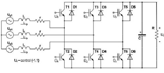
Fig (a) Three-Phase Boost Rectifier[8]
Fig shows the three-phase boost Rectifier used to convert 3 phase AC power into DC power. The boost rectifier circuit is mainly divided into three parts such as storage element, bidirectional switches and RC filter. The inductor is used as a storage element it is used for higher order dc voltage that could be obtained by the rectifier. The IGBT with the anti-parallel diode is used as bidirectional switches and for reducing the output variations RC filters is used. There are three control signals: U1, U2, and U3, which can take values from the finite set {−1, 1}. For example, having control U1 = 1 means U1 = −1 and corresponds to the conducting state for the upper switching element T1 and non-conducting state for the bottom switching element T2. Three controls provide conducting states for three out of six switching elements at any time moment. The mathematical model which describes the circuit behaviour is given in scalar format [8].
=− + 1
=− +
6 2 − − −
1
3 (2 − − )
=− +
6 2 − − −
1
3 (2 − − )
=− + ( + + )
and in vector format (1)
=− − +
(2)
=− +
Where,
r- Internal (parasitic) phase resistance (introduced as a voltage source internal resistance and impedance of switching elements in open state);
R -output (load) resistance;
L -phase inductor (assumed to be the same for all phases); C -output capacitor;
U0 -converter output voltage (available for measurement);
i ={i1,i2,i3}Vector of input phase currents (available for measurement);
Ug = {Ug1, Ug2, Ug3 }T vector of input (main) voltages(available for measurement);
U = {U1, U2, U3}T vector of controls.
Each Uj is defined on the finite set of values {+1,−1}. Gain matrix is defined as
=
2 −1 −1
−1 2 −1
−1 −1 2
(3)
Assuming the harmonic character of the main voltages Ugj which have different magnitudes but the same frequency and phase shift of (2π/3) electrical degrees (with respect to each other), vector Ug can be expanded as follows[8]
=
0 0
0 0
0 0
sin( )
sin ( + )
sin ( − )
=E*sin (4)
Where
E j is the magnitude of the jth phase mains voltage.
The control objectives are as follows.
1) The dc component of the output voltage should be equal to some desired constant value Vd while the AC Portion of the output voltage should be reduced to an acceptable range.
Solvability of the Problem
The solvability condition of the problem affects the upper bound of circuit magnification gain. In other words, the maximal output voltage that can be stabilized by the circuit appears to be a function of main voltage magnitudes and circuit parameters. The problem solvability condition is to be expressed in terms of the attractive magnitudes of input phase currents. Such magnitudes should be chosen to provide the dc power balance between the input and output sides of the converter while maintaining the desirable dc level of the output voltage. This has been performed into[8] obtaining the following,
= − − (5) It is preferred current profile for each phase ,Vd is a preferred voltage level and the condition of Vd in order to keep Idj
real is the following
≤ 3
8
This corresponds to upper limit for Vd.
Similarly the phase voltage, the desired phase current can be written as
=
0 0
0 0
0 0
sin( )
sin ( + )
sin ( − )
= *sin (6)
Since the desired phase current curve need to be in phase with their corresponding phase voltage curve if the power factor improves [8].
III. SLIDING MODE CONTROLLER
Sliding mode control is a nonlinear method of control. It alters the dynamics of any nonlinear system by application of an irregular control signal. Maintain stability and give consistency performance is done by sliding mode controller. To drive nonlinear plant’s state trajectory into a pre-specified surface and to keep plant’s state trajectory for subsequent time are the general function of switching control law. The surface is known as switching surface which defines rules for proper switching; this surface is known as a sliding surface. There are two paths. Feedback path has one gain when plant the trajectory is above the surface and a different gain when trajectory is below the surface. Stabilization, regulation, tracking this type of conventional control method can be obtained by proper design of sliding surface [13].
Sliding Mode Controller For Boost Rectifier
The Sliding mode current control technique is implemented for power factor improvement of the boost converter. The design of an SMC, the input current i had to follow the reference signal di .However, first of all, we have to discuss the control obstacles to overcome. The control vector U looks in the system equations through the singular gain matrix. This fact produces to a loss of controllability in the case when U= {1, 1, 1} or U= {−1, −1,−1}. At first, we have to introduce three sliding variables1 , , combine them into the vector format = { , , } . Every scalar quantity represents the current tracking error in the equivalent phase [6]. Convergence of all tracing errors is the responsibility of the controller is provided for the all sliding variable to make zero.. The error is,
The sliding variable are supposed to derive zero = − − ∫( + + ) (9)
According to Kirchhoff’s current law, it is not required to track all three phase currents at the similar time. Also, tracking the third current gives rise a singularity. The third condition evades the unnecessary requirement to track the third current and is used to claim control symmetry. In the process of controller design, we have to now find the derivatives of sliding variables along the system trajectory [9].
=
− ( )
− +
+ +
= + (10)
Where, =
(2 − − −3 ) sin( )− ( ) +
(2 − − −3 ) + − + +
0
(11)
=
1 1 1
, U= , = ( + + ) (12)
Here is a nonsingular matrix. So U can be decoupled by the following equation.
∗= ∗= + . . = + Where, = ⎣ ⎢ ⎢ ⎢ ⎡ 0 0 ⎦ ⎥ ⎥ ⎥ ⎤ (13)
The control function become, = sin ∗ j=1,2,3[9].
But the power factor is not improved to unity so we include the PWM controller with sliding mode controller.
PWM to theSliding Mode Controller For Boost Rectifier
Pulse Width Modulation (PWM) is the very useful technique for boost rectifier circuit to the improvement of the power factor. The Main objectives in the control of boost rectifier are to achieve high power factor and minimum harmonic distortion in the input line current. The advantages of the PWM is to achieve the high power factor and less harmonics it is used to regulate the dc output voltage.PWM is used by fixing the frequency of its ramp signal , the frequency of the output switching signal will be constant. In pulse width modulation rectangular pulse wave is used which result in the variation of the average value of the waveform. Consider a pulse Waveform f(t)with the minimum value y min, a
maximum value y max and a duty cycle D, then the average value of waveform can be given by the expression
Where ymax is 0< < . Ymin is D.T< <
Therefore,
Y= (∫ +∫ )
= . . ( ) =D.T max+(1-D)Y min
It Can be simplified putting Y min=0so y=D.y max therefore average value of signal is directly dependant on duty cycle D [13].Hence Sliding mode is developed using the PWM technique for improving power factor to unity to the boost rectifier circuit.
IV. SIMULATION RESULT
The simulation shows the various result of three-phase boost rectifier using sliding mode controller with the PWM technique. Figure (a) shows the simulation of the three-phase AC Input supply given to the boost rectifier circuit. This figure shows the three-phase AC input Voltage and three-phase AC input current given to the three-phase boost rectifier circuit.
Figure (a) 3 Phase AC Input Current and 3 Phase AC Input Voltage
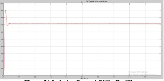
Figure (b) shows the simulation result of the inductor current of the three-phase rectifier circuit.Three-phase AC supply is given to the three-phase boost rectifier circuit and get the DC output current and voltage as shown in figure (b) and figure (c).The inductor current range is shown in fig (b).
Figure (c) shows the simulation result of the output voltage of three-phase rectifier. The value of the output voltage is near about 180 V as shown in the figure. The output voltage of the rectifier is less it is not equal to desirable constant level hence there is the need to output voltage was boosted to the higher voltage level for improving the power factor.
Figure (c) output Voltage of the Rectifier
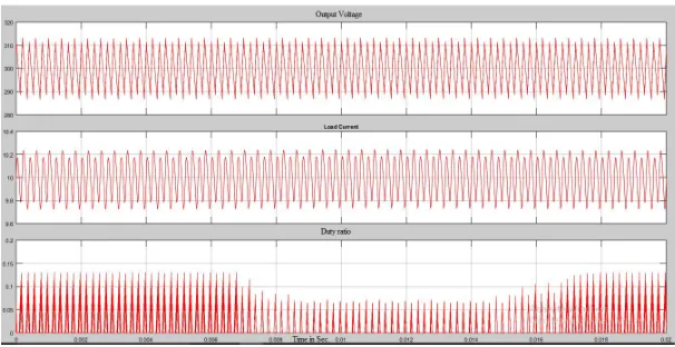
Figure (d) shows the Simulation result of the output voltage, load current and duty ratio of three -phase boost rectifier circuit using sliding mode controller. This result shows the output voltage is boosted to the higher voltage level near about 300 V as shown in figure (d).The rectified output voltage and output current can be control by sliding mode controller. In this controller, PWM technique is also used. The sliding mode controller modified with pulse width modulation for controlling the boost rectifier circuit and gets the power factor ne unity. With the help of this modified controller, the output voltage is boosted and the duty ratio of the current and voltage is nearby 0.1 as shown in the figure and get the regulated output voltage. Current can be control 10.2 A with the help of SMC with PWM as shown in figure (d).
Figure (d) Output Voltage, Load Current and Duty Cycle Using SMC
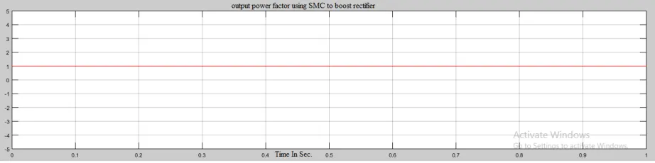
mode controller and the control signal is maintained so the power factor is control. Then the power factor improved nearby unity by using PWM controller in the sliding mode controller as shown in figure (e).
Figure (e) Power Factor using SMC to The Boost Rectifier Circuit
With the help of this simulation result various issues that should be clarified such as output voltage was boosted to the higher voltage level and get regulated dc output voltage, control the current and voltage of rectifier and improve the power factor up to unity.
V. CONCLUSION
The simulation of sliding mode controller is present in this study. For improvement of power factor and controlling the three-phase boost rectifier circuit, the sliding mode controller is designed with PWM technique. The proposed control scheme was shown to be robust with respect to load. The control result in the system improves the power factor nearby unity and output voltage was boosted to the higher voltage level. The simulation result show the control technique of sliding mode controller using PWM technique for three-phase boost rectifier model can improve the power factor to unity and robustness due to change in load and get the regulated dc output voltage.
REFERENCES
[1] M. H. Rashid, Power Electronics: “Circuits, Devices and Applications (3rdEdition), Prentice Hall”, 2003.
[2] N. Mohan, et el. Power Electronics: Converters, Applications, and Design. New York: NY, USA, John Wiley & Sons, Inc., 1995.
[3] A. R. Prasad, Phoivos D. Ziogas, and Stefanos Manias, “An Active Power Factor Correction Technique for Three- phase Diode Rectifiers”, IEEE transactions On Power Electronics, vol. 6 (1991).
[4] B. Singh, B.N. Singh, A. Chandra, K. Al-Haddad, A. Pandey, D.P. Kothari, “A Review of Three-phase Improved Power Quality AC/DC Converters‖”, IEEETRANS. IND. ELECTRON VOL 51, (2004).
[5] Hanifi Guldemir, “Sliding Mode Control of DC-DC Boost Converter”, journal of Apllied Science 5(3)588-592,2005
[6] S.C.Tan,Y.M.Lai,C.K.Tse,”Implementation of Pulse Width Modulation Based Sliding Mode Controller For Boost Converter” IEEE Power Electronics Letters, Volume 3,no 4,December2006.
[7] S.-C. Tan, Y. M. Lai, C. K. Tse, L. Martinez-Salamero, and C.-K.Wu,“A fast-response Sliding-mode controller for boost-type converters with a wide range of operating conditions”, IEEE Trans. Ind. Electron., vol. 54,no. 6, pp. 3276–3286, Dec. 2007.
[8] Yuri Shtessel,Simon Baev,Haik Biglari “Unity Power Factor in Three-Phase AC/DC Boost Converter Using Sliding Modes”IEEE Transaction on. industrial electronics Vol 55 NO,11 November 2008.
[9] R. Schaeffer, Y. Steele, S. Baev, and H. Biglari, “3-Phase AC/DC Boost Converter Power Factor Control via Traditional and Second Order Sliding Modes”, 2010American Control Conference Marriott Waterfront, Baltimore, MD,USA June 30-July02, 2010
[10] Syama P S,Anasraj R, “Robust Sliding Mode Controller For A voltage Regulated Quadratic Boost Converter”,2010 international Conference on next generation intelligent system(ICNGIS),2010
[11] Mitulkumar R. Dave, K.C.Dave, “Analysis of Boost Converter Using PI Control Algorithms‖, International Journal of Engineering Trends and Technology- Volume3Issue2- 2012
[12] Jianxing Liu,Salah Laghrouche, Maxime Wack, “Output High Order Sliding Mode Control Of Unity Power Factor In Three Phase AC/DC Boost Converter”12th IEEE Workshop on variable structure System VSS’12January 12-14Mumbai 2012.
[13] S,S,Muley, R.M.Nagarale, “Sliding Mode Control Of Boost converter”, IJETAE (ISSN 2250-2459,ISO 9001:2008 certified journal ,Volume 3 Issue 9,September 2013)