Type of the Paper (Article, Review, Communication, etc.)
1
Maximum Power Point Tracking for Brushless DC Motor
2
Driven Photovoltaic Pumping System Using Hybrid
3
ANFIS-FLOWER Pollination Optimization Algorithm
4
Neeraj Priyadarshi1,*, Sanjeevikumar Padmanaban 2, Lucian Mihet-Popa 3, Frede Blaabjerg 4, and
5
Farooque Azam1
6
1 Department of Electrical and Electronics Engineering, Millia Institute of Technology, Purnea, India;
7
[email protected], [email protected]
8
2 Department of Energy Technology, Aalborg University, 6700 Esbjerg, Denmark; [email protected]
9
3 Faculty of Engineering, Østfold University College, Kobberslagerstredet 5, 1671 Kråkeroy-Fredrikstad, Norway;
10
11
4 Center for Reliable Power Electronics (CORPE), Department of Energy Technology, Aalborg University,
12
Aalborg, Denmark; [email protected]
13
* Correspondence: [email protected]; Tel.: +47-922-713-53
14
15
Abstract: In this research paper, a hybrid Artificial Neural Network (ANN)-Fuzzy Logic Control (FLC)
16
tuned Flower Pollination Algorithm (FPA) as a Maximum Power Point Tracker (MPPT) is employed to
17
emend root mean square error (RMSE) of photovoltaic (PV) modeling. Moreover, Gaussian membership
18
functions have been considered for fuzzy controller design. This paper interprets Luo converter occupied
19
brushless DC motor (BLDC) directed PV water pump application. Experimental responses certify the
20
effectiveness of the suggested motor-pump system supporting diverse operating states. Luo converter is
21
newly developed dc-dc converter has high power density, better voltage gain transfer and superior
22
output waveform and able to track optimal power from PV modules. For BLDC speed controlling there is
23
no extra circuitry and phase current sensors are enforced for this scheme. The recentness of this attempt is
24
adaptive neuro-fuzzy inference system (ANFIS)-FPA operated BLDC directed PV pump with advanced
25
Luo converter has not been formerly conferred.
26
Keywords: ANFIS, artificial neural network, brushless DC motor, FPA, maximum power point tracking,
27
photovoltaic system, root mean square error.
28
29
1. Introduction
30
As the conventional energy sources are depleting day by day, the demand of renewable energy
31
sources are raising with considered attention [1-3]. Solar energy sources are promising renewable energy
32
sources for developed and developing nations due to free, abundant and environmental friendliness
33
nature. The standalone photovoltaic (PV) systems for water pumping applications are employed for
34
remote areas [4-5]. Because of grid absence in remote places the standalone PV water pumping is installed
35
for agricultural and household applications. Various electric motors have been used to drive the
36
pumping system [6-7]. The DC motor based pumping system requires maintenance because of
37
commutator and brush presence. Therefore, DC motors are not frequently used for PV pumping
38
applications. The single phase induction motors have also been used for driving low inertia torque load.
39
40
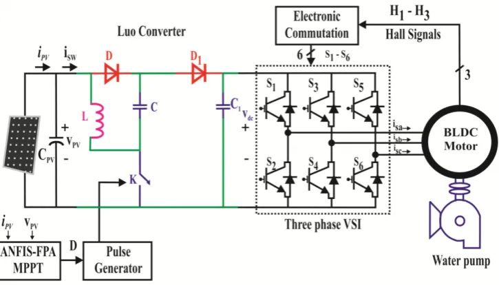
Figure 1 BLDC driven Photovoltaic Complete System Formation
41
Due to complex control strategy, the induction motors are not efficient for pumping applications.
42
Therefore, in this research work Brushless DC (BLDC) motor has been considered as it has simple design
43
control, low power range and require maintenance free operation compared to AC motors [8].
44
Distinct DC-DC converters were contend for optimizing PV module generated power with soft
45
starting and controlling motor pump system [9-11]. The contemporary PV system has unsubstantial
46
converse competency. Therefore, Maximum Power Point Trackers (MPPT) is the indispensable
47
constituents required for optimal power tracking from PV modules. In contrast with different employed
48
power converters, modern Luo converter has been considered for this research approach as it delivers
49
better power/ density ratio with economical implementation [20]. Numerous MPPT methods have been
50
occupied viz. Perturb and Observe (P&O), Increment Conductance (INC), Fraction Short/Open circuit etc.
51
[12-14]. Under steady state operating conditions particular algorithms provide high outturn. But these
52
algorithms are found lacking under adverse weather conditions with slow convergence velocity and
53
unable to achieve global power point (GPP) for partial shading situations with high power oscillations
54
around this point. Recently different intelligent techniques viz. Fuzzy Logic Control (FLC), Artificial
55
Neural Network (ANN) has been employed for PV tracking [15]. However, because of complex fuzzy
56
inference rules and individual sensor requirements, meta-heuristic algorithms have been employed
57
nowadays. Genetic algorithm and artificial Immune system are meta-heuristic algorithms used for
non-58
linear stochastic problem solution. However, the implementation of selection, mutation and crossover
59
process is complex with reduced convergence computational period. Currently, Bio-inspired and swarm
60
optimization have been derived as MPPT techniques. The particle swarm optimization is an evolutionary
61
methodology based on nature of swarm is able to reduce oscillations around GMPP [16-18]. Nevertheless,
62
variance of this algorithm is capitulated when randomness is miniaturized. Surrogating to swarm
63
techniques, currently bio-inspired algorithms viz. Firefly Algorithms (FA), Artificial Bee Colony (ABC),
64
Cuckoo Search etc. have been considered as bio-inspired MPPT and has advantage of high convergence
65
speed, less transient with fast tracked performance. However, the implementation complexities with
66
tuning of parameters are the major hindrance of this finding. Included work, a novel flower pollination
67
algorithm is contemplated and associated with hybrid ANFIS MPPT algorithm. The hybrid ANFIS-
68
Flower Pollination Algorithm (FPA) [19] has simple implementation, high convergence speed with tune
69
BLDC drive PV pumping employed Luo converter [20] with hybrid ANFIS-FPA have not been conferred
71
and examined using dSPACE (DS1104) platform under changing weather conditions.
72
2. Complete System Formation
73
Fig 1 illustrates the Luo converter employed BLDC driven PV pumping for remote location. A hybrid
74
ANFIS-FPA MPPT controller is operated to produce required pulse for power switched of Luo converter.
75
This converter delivers better power/ density ratio with economical implementation with interface
76
between inverter power circuit and solar system. Moreover, electronic commutation methodology
77
controls voltage source inverter (VSI) employed BLDC motor in which winding current is adjusted with
78
the help of decoder in proper sequence.
79
2.1 PV Generator
80
81
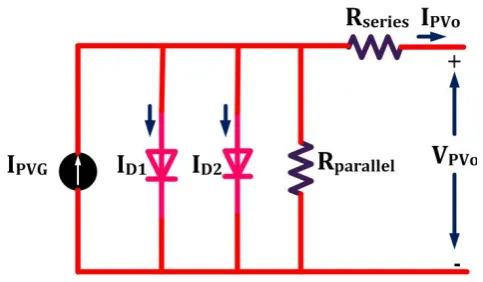
Figure 2 Two diode PV cell model
82
In this research work a two diode PV cell model is considered (Figure 2) because of simple and
83
accurate model compared to single diode PV cell. By means of photoelectric effect, the conversion of solar
84
to electricity takes place and output power can be enhanced by connecting numerous solar cells in shunt
85
or series as per requirement. Both diodes employed to represent polarization occurrence with current
86
source exhibiting sun insolation followed by power loss delivered by resistances (series/shunt) used. The
87
prognosis of overall system is calculated on the basis of accurate equivalent modeling. The output of PV
88
current is expressed mathematically as:
89
I = I − I I′+ 2 − ∗ (1)
90
Where,
91
I′= exp ∗ + exp ∗
∗ (2)
92
IPVG = Photo Current
93
IRSC = Diode reverse saturation current
94
IPVO = Output PV current
95
VPVO = PV output voltage
96
VThermal = PV module thermal voltage
98
A = Ideality constant of diode
99
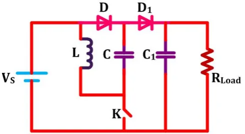
2.2 Luo Converter
100
Renewable technology comprises dc-dc topologies for yield of energy harvest with admissible
101
proficiency. With respect to other dc-dc converters, modern Luo topology depicted in Fig 3 delivers
102
reasonable cost, better power/ density ratio and enhanced transformation efficiency. It comprises least
103
ripple content with geometric output voltage and surpasses the parasitic element action. The auxiliary
104
benefit of this topology is switched components are taken ground as a reference. In addition to that the
105
input inductor smoothes the ripple present to input source. Employed capacitors get charged to stated
106
value to accomplish high voltage leveled.
107
108
Figure 3 Power Circuit Luo converter
109
Transfer gain voltage is evaluated as:
110
duty duty S d d V V − −= 2 1
0 (3)
111
Relation between inductor ripple current and duty cycle is expressed as:
112
L f d V I Pulse duty SLRipple ∗
∗ =
Δ (4)
113
Capacitors (C=C1) values are determined mathematically as:
114
(
)
0 0 1 1 V R f V d C C Load Pulse duty Δ ∗ ∗ ∗ − == (5)
115
Where, dduty= Duty ratio
116
fPulse= Frequency of Switched pulse
117
2.3 A Hybrid Proposed FLC-ANN tuned FPA MPPT
118
In this proposed scheme, hybrid ANFIS-FPA MPPT algorithm is realized for maximizing PV outturn
119
and accurate motion control with PV-pump interface. The FLC data is trained by ANN which finally
120
optimized by FPA method lead to minimum RMSE of FLC and ANN. It comprises the dominance of FLC
121
minimum RMSE. Figure 4 depicts the complete structure of hybrid learning in which learning data has
123
been achieved from FLC architecture.
124
125
Figure 4 complete structure of hybrid ANFIS-FPA
126
The FLC architecture comprises fuzzification, Inference Rule base and defuzzification as elemental
127
constituents. Real variables are converted to linguistic parameters using fuzzification. The requisite
128
output introduced by Mamdani fuzzy inference rule deployed by max-min composition. With the help of
129
centroid method, the defuzzification process converts the linguistic parameters to real values. Employed
130
membership values are illustrated by Fig 5.
131
132
Figure 5 Employed membership values
133
The ANN objective function is expressed mathematically as:
134
RMSE = ∑ − / (6)
135
Where,
136
YF = Fuzzy output
138
YN = Neural Network output
139
FPA method of MPPT is predicted by reproduction of flower of transferring pollen. This convection is
140
possible through biotic/cross and abiotic/self pollination. In cross pollination the pollens are translated
141
between two unlike flowers. On the other hand abiotic pollination takes place between distant species. It
142
is noted that in flower pollination 90% possibility of cross pollination and only 10% possibility of self
143
pollination happen which is limited in the probability range R ɛ [1, 0]. The complete process is based on
144
following rules:
145
Rule I: The biotic pollination use levy flight for transferring pollens and called global pollination in which
146
ith pollen solution vector is expressed mathematically as:
147
X = X + L ∗ X −G (7)
148
Where,
149
= Vector representing solution
150
T = No. of iteration
151
Lf = Levy flight factor
152
Gbest = Global best solution
153
Rule II: Self pollination is termed as local pollination and characterized mathematically as:
154
X = X + P ∗ X −X (8)
155
X and X = two unlike pollen in the species
156
Pf = Switched probability
157
Rule III: The performance of flower is assumed identical to the probability of reproduction that
158
equivalent with resemblance of two concerned flowers.
159
Rule IV: The pollination is interchanged within global to local depends on switching probability lies at
160
interval between 0 and 1.
161
2.4 Electronic BLDC Commutator and VSI switching
162
Commutation in Permanent Magnet DC Motor (PMDC) is obtained by commutator and brushes.
163
Nevertheless, hall sensors are important component employed in BLDC motor which senses the position
164
of rotor as a commutation wave. Coils and permanent magnet are employed as a stator and rotor
165
respectively in which stator’s magnetic field rotates rotor. Armature of BLDC motor consists of permanent
166
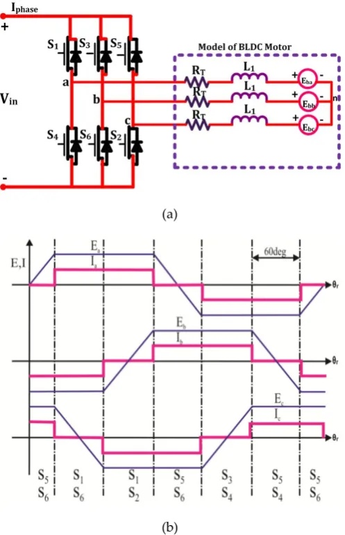
magnet as a substitute of coil which does not require brushes. Figure 6 demonstrates BLDC driven
167
169
(a)
170
171
(b)
172
Figure 6 BLDC driven structure with induced EMF and reference current
173
The BLDC motor is analyses mathematically as:
174
V V V
=
R 0 0 0 R 0 0 0 R
I I I
+
L − M 0 0
0 L − M 0
0 0 L − M
I I I
+ E E
E (9)
175
Developed electromagnetic torque by BLDC motor can be expressed mathematically as:
176
= ∗ ∗ ∗
(10)
177
Where,
178
Vap, Vbp, Vcp= Phase voltage of a 3-Phase BLDC motor
179
Iap, Ibp, Icp= Phase Currents
180
L1 = Each Phase self-inductance
182
M1 =Two phase’s mutual inductance
183
TEM = Developed Electromagnetic torque of BLDC motor
184
ωRotor = Rotor Speed
185
186
Figure 7 gating signal for 3-phase VSI
187
Electronic commutation process is used to control the VSI employed BLDC motor in which winding
188
current is adjusted with the help of decoder in proper sequence. In this method, symmetrical DC currents
189
are situated to the phase voltage at 120º. Based on the motor alignment, the hall sensors produces signals
190
of 60º phase difference. The gating signal for 3-phase VSI is generated by transforming hall signals using
191
decoder is illustrated by Fig 7. The pulse width modulated pulses are generated by comparing triangular
192
signal with duty cycle produced through MPPT. Table 1 portrays Hall signals and Switching states of
193
BLDC used with Electronic commutation.
194
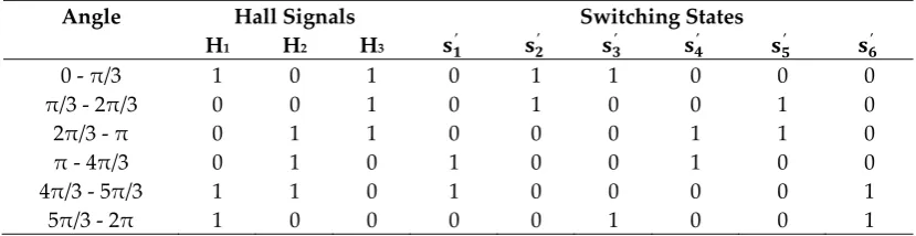
Table 1 Hall signals and Switching states
195
Angle Hall Signals Switching States
H1 H2 H3 ′ ′ ′ ′ ′ ′
0 - π/3 1 0 1 0 1 1 0 0 0
π/3 - 2π/3 0 0 1 0 1 0 0 1 0
2π/3 - π 0 1 1 0 0 0 1 1 0
π - 4π/3 0 1 0 1 0 0 1 0 0
4π/3 - 5π/3 1 1 0 1 0 0 0 0 1
5π/3 - 2π 1 0 0 0 0 1 0 0 1
196
The high frequencies PWM pulses and six fundamental signals are operated with AND gate, which
197
produces 6 gating pulses for VSI inverter. As the atmospheric conditions changes, the duty cycle is also
198
regulated using MPPT methods which controls the VSI and finally the BLDC motor is adjusted
199
accordingly.
200
3. Experimental Results
201
203
Figure 8 BLDC driven Luo converter employed PV pumping hardware developed
204
Performance justification of BLDC driven PV pumping employed Luo converter has been done through
205
dSPACE controller. For purpose of MPPT operation, LA-55/LV-25 as current/voltage sensors is employed
206
during practical implementation. Fig 8 portrays the BLDC driven Luo converter employed PV pumping
207
hardware developed in the laboratory. With the help of A/D converter, analog pulses are transformed to
208
digital and fed to dSPACE interface. Electronic commutation/Controlling BLDC has been executed by
209
obtained hall pulses from input/output terminal and then generated pulses are outturned to inverter.
210
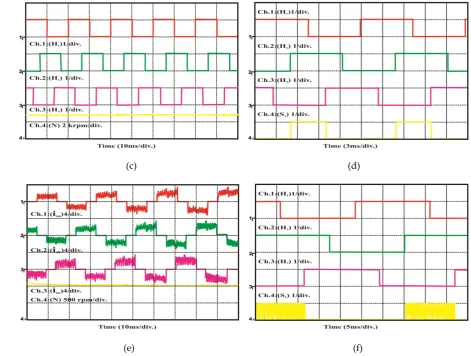
3.1 Steady State Performance
211
The experimental behaviors of PV module and motor pumping system have been tested under steady
212
state condition of irradiance level 1000w/m2. The proposed MPPT design technique is working effectively
213
and tracks optimal power from PV module with unity duty cycle at 1000 W/m2 solar insolation level
214
depicted in Fig 9. The corresponding BLDC motor and torque (1500 rpm) has been demonstrated in Fig 9
215
(d) presents the obtained hall sensor pulses with motor torque. The performance of BLDC motor-
216
pumping system has been evaluated with 300 W/m2 solar irradiance. The motor torque is experimentally
217
obtained which is sufficient to operate PV water pumping. Based on duty cycle generation using MPPT
218
algorithm, the corresponding hall signals have been generated to trigger six switches of inverter.
219
220
221
223
(c) (d)
224
225
(e) (f)
226
Figure 9 BLDC driven Luo converter employed PV pumping (a) PVG at 1000 W/m2 (b) BLDC performance
227
at 1000 W/m2 (c) generated hall sensor pulses at 1000 W/m2 (d) switched and hall pulses at 1000 W/m2 (e)
228
BLDC performance at 300 W/m2 (f) switched and hall pulses at 300 W/m2
229
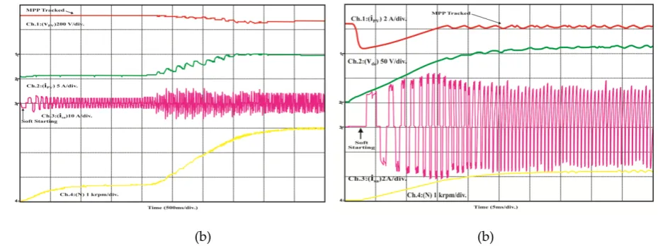
3.2 Dynamic Behavior of PV system
230
The effective practice of recommended PV pumping system was proved under varying sun insolation
231
level. In this experiment, solar irradiance level is varied from 300W/m2to 1000W/m2. According to
232
variation in sun irradiance level , corresponding changes in PV current, DC link voltage , BLDC stator
233
current and motor torque have been verified (Fig 10) and PV pumping is running without any
234
interruption. The duty cycle for BLDC-PV pump control is generated with variation in sun insolation
235
237
(a) (b)
238
Figure 10 BLDC driven Luo converter (a) increased solar irradiance (b) decreased solar irradiance
239
3.3 Behavior at Starting
240
Practical results found in Fig 11 interpret the safe starting of BLDC motor under irradiance level
241
1000W/m2 and 300W/m2. Initially the duty cycle is kept 0.5 to run the motor. The sufficient motor speed is
242
obtained by controlling the starting current which runs the motor-pump system successfully. Fig
243
11portrays the successful action of BLDC-PV pump at start by limiting starting current which reveals the
244
progression with safe and soft started.
245
246
247
(b) (b)
248
Figure 11 BLDC driven Luo converter employed PV pumping under soft starting (a) 1000 W/m2 (b) 400
249
W/m2
250
Table 2 Laboratory adopted BLDC specification
251
S.N Parameters Value
1. Resistance of stator 4.16Ω
2. Inductance value of stator 2.2 mH
3. Speed rating 1500rpm
5. Constants(Voltage & torque) 86VLL/KRPM & 0.85 Nm/Ampere
252
Table 2 portrays laboratory adopted BLDC specification for motion control PV pump. Fig 12 interprets the
253
existent global nature of PV system under divergent sun radiation which is demonstrated by dark line.
254
The operation begins with VOPEN Ckt state and reaches to global power point with variable solar irradiance.
255
With application of hybrid ANFIS-FPA MPPT, steady GMP is attained over a complete day.
256
The performance of MPPT controllers are tested with stepped irradiance input. Under these situations,
257
ANFIS-FPA has high tracked PV power with proportionately lesser GMP time. Practical results
258
demonstrate that ANFIS-FPA algorithm contributes rapid and insignificant swinging differentiated with
259
FPA MPPT illustrated by Fig 13 (a) and (b).
260
Fig 14 demonstrates the behavior of numerous MPPT control under standard test conditions. A hybrid
261
ANFIS-FPA algorithm has global power point trajectory with utmost PV tracked power and has zero
262
oscillation throughout equated with different controllers. The PV tracked trajectories are also examined
263
under fluctuating weather situations (Fig 15). Practical results reveal that ANFIS-FPA optimized MPPT
264
provides optimal tuning with high performance index.
265
266
267
269
(a) (b)
270
Figure 13 Behavior of MPPT under stepped irradiance (a) Hybrid ANFIS-FPA (b) FPA
271
272
274
Figure 15 PV tracked trajectories examined under fluctuating weather situations
275
4 Conclusion
276
The Luo converter based BLDC driven PV pumping with ANFIS-FPA MPPT has been demonstrated
277
under varying weather conditions using dSPACE platform. The Luo converter has been proposed for
278
desired GMP functions. The PV fed BLDC motor drive pumping system operates effectively under steady,
279
dynamic state and soft starting operating conditions which validated through experimentally obtained
280
responses. The enforcement of ANFIS-FPA MPPT controller has been equated with general P&O and
281
ANFIS-PSO method which gives high tracking efficiency, fast design and rapid convergence time under
282
varying solar irradiance level.
283
Author Contributions: All authors contributed equally for the decimation of the research article in current form.
284
Conflicts of Interest: The authors declare no conflict of interest.
285
286
References
287
[1] Jedari M, fathi S H. A New Approach for Photovoltaic Arrays Modeling and Maximum Power Point
288
Estimation in Real Operating Conditions. IEEE Trans. on Ind. Electron. 2017; 64(12): 9334 – 9343.
289
[2] Aamri F EL, Maker H, Sera D, Spataru S, Guerrero J M, Mouhsen A. A Direct Maximum Power Point
290
Tracking Method for Single-Phase Grid Connected PV Inverters. IEEE Trans. on Power Electron.
291
2017; (99): 1-10.
292
[3] Tiwari S K, Singh B, Goel P K. Design and Control of Autonomous Wind-Solar System with DFIG
293
Feeding 3-Phase 4-Wire Loads. IEEE Trans. on Ind. Appl. 2017; (99): 1-8.
294
[4] Kumar R, Singh B. BLDC Motor Driven Solar PV Array Fed Water Pumping System Employing Zeta
295
Converter. IEEE Trans. on Ind. Appl. 2016; 52(3): 2315 – 2322.
296
[5] Montorfano M, Sbarbaro D, Mor´an L. Economic and technical evaluation of solar assisted water
297
pump stations for mining applications: A case of study. IEEE Trans. on Ind. Appl. 2016; 52(5): 4454 –
298
[6] Alghuwainem S M. Speed Control of a PV Powered DC Motor Driving a Self- Excited 3-Phase
300
Induction Generator for Maximum Utilization Efficiency. IEEE Trans. on Energy Conversion. 1996;
301
11(4): 768-773.
302
[7] Jain S, T K A, Karampuri R, Somasekhar V T. A Single-Stage Photo Voltaic System for a Dual-
303
Inverter fed Open-End Winding Induction Motor Drive for Pumping Applications. IEEE Trans. on
304
Power Electron. 2015; 30(9): 4809 - 4818.
305
[8] Sashidhar S, Fernandes B G. A Novel Ferrite SMDS Spoke-Type BLDC Motor for PV Bore-Well
306
Submersible Water Pumps. IEEE Trans. on Power Electron. 2017; 64(1): 104-114.
307
[9] Killi M, Samanta S. An Adaptive Voltage Sensor Based MPPT for Photovoltaic Systems with SEPIC
308
Converter including Steady State and Drift Analysis. IEEE Trans. on Power Electron. 2017; 64(1):
104-309
114.2015; 62(12): 7609 – 7619.
310
[10] Priyadarshi N, Kumar V, Yadav K, Vardia M. An Experimental Study on Zeta buck-boost converter
311
for Application in PV system. Hand book of distributed generation.
DOI10.1007/978-3-319-51343-312
0_13.
313
[11] Priyadarshi N, Anand A, Sharma A K, Azam F, Singh V K, Sinha R K. An Experimental
314
Implementation and Testing of GA based Maximum Power Point Tracking for PV System under
315
Varying Ambient Conditions Using dSPACE DS 1104 Controller. Int. Journal of Renewable Energy
316
Research, 2017; 7(1): 255-265.
317
[12] Kumar N, Hussain I, Singh B, Panigrahi B K. Framework of Maximum Power Extraction from Solar
318
PV Panel using Self Predictive Perturb and Observe Algorithm. IEEE Trans. on Sustainable Energy.
319
2017; (99): 1-9.
320
[13] Elgendy M A, Zahawi B, Atkinson D J. Assessment of the Incremental Conductance Maximum
321
Power Point Tracking Algorithm. IEEE Trans. on Sustainable Energy. 2013; 4(1): 108-117.
322
[14] Zamora A C, Vazquez G, Sosa J M, Rodriguez P R M, Juarez M A. Efficiency Based Comparative
323
Analysis of Selected Classical MPPT Methods. IEEE Int. Autumn Meeting on Power, Electronics and
324
Computing. 2017; 1-6.
325
[15] Abu-Rub H, Iqbal A, Ahmed SK M, Peng F Z, Li Y, Baoming G. Quasi-Z-Source Inverter-Based
326
Photovoltaic Generation System With Maximum Power Tracking Control Using ANFIS. IEEE Trans.
327
on Sustainable Energy. 2013; 4(1): 11-20.
328
[16] Priyadarshi N, Sharma A K, Azam F. A Hybrid Firefly-Asymmetrical Fuzzy Logic Controller based
329
MPPT for PV-Wind-Fuel Grid Integration. Int. Journal of Renewable Energy Research. 2017; 7(4):
330
1546-1560.
331
[17] Sundareswaran K, Sankar P, Nayak P S R, Simon S P, Palani S. Enhanced Energy Output From a PV
332
System Under Partial Shaded Conditions Through Artificial Bee Colony. IEEE Trans. on Sustainable
333
Energy 2015; 6(1): 198-209.
334
[18] Kalaam R N, Muyeen S M , Al-Durra A, Hasanien H N, Al-Wahedi K. Optimisation of controller
335
parameters for grid tied photovoltaic system at faulty network using artificial neural network-based
336
cuckoo search algorithm. IET Renewable Power Gen. 2017; 11(12): 1517-1526.
337
[19] Ram J P, Rajasekar N. A novel Flower Pollination based Global Maximum Power Point method for
338
Solar Maximum Power Point Tracking. IEEE Trans. on Power Electron. 2017; 32(11): 8486 – 8499.
339
[20] Pansare C, Sharma S K, Jain C, Saxena R. Analysis of a Modified Positive Output Luo Converter and