DOI: http://dx.doi.org/10.26483/ijarcs.v9i2.5676
Volume 9, No. 2, March-April 2018
International Journal of Advanced Research in Computer Science
RESEARCH PAPER
Available Online at www.ijarcs.info
ISSN No. 0976-5697
IMPORTANCE OF NON-LINEAR CONTROLLER IN IMPLEMENTING
ANTI-LOCK BRAKING SYSTEM- A TECHNICAL REVIEW
Dankan V Gowda
Department of Computer Science and Engineering Nitte Meenakshi Institute of Technology, Bangalore,
Karnataka, India
Ramachandra A C
Department of Computer Science and Engineering Nitte Meenakshi Institute of Technology, Bangalore,
Karnataka, India
Abstract: Anti-lock braking systems (ABS) is a safety and management devices enforced in ground vehicles that forestall the wheel lock-up throughout emergency braking. The most operate of ABS is to cut back the vehicle stopping distance and stopping time. Stopping distance is the distance travelled by the vehicle after applying the brake and time for the vehicle to reach to complete halt is stopping time. We can, in general consider a controller as a good controller if it helps to reduce both stopping distance and time. Under the influence of Drive torque, the vehicle moves and due to air drag, braking torque, surface friction and inertia, vehicle come to stop. A vibrant arrangement of all these torques and forces are accountable for motion of vehicle on a surface and coefficient of friction between tire and road-surface, amount of steering etc contribute further to vehicle dynamics. Due to drive torque obtained by engine, the wheels starts revolving and when brake applied it comes to arrest after sometime. Vehicle speed and wheel angular rapidity are relative in normal condition but when solid braking is made it is probable that vehicle speed is not drop down at the indistinguishable rate as wheel rotational speed, causing the slip. Slip is a condition created by locking of wheels, means wheels not rotating but vehicle is moving. This is a fatal driving condition and driver can lose the control of vehicle and the time to stop the vehicle increases. By controlling the Brake Pressure the Antilock Braking system matches the wheel speed and the vehicle speed, which intern results vehicle will be under stable zone. However, the ABS shows physically powerful nonlinear individuality in which the vehicles equipped with the accessible controllers can still have a predisposition to oversteer and become unbalanced. Many diverse control methods for ABS systems have been developed. These methods diverge in their hypothetical basis and performance under the changes of road circumstances. In this paper, an effort is made to evaluate the variety of nonlinear controllers used in the execution of ABS systems and also address the main difficulties concerned in designing such a systems and summarize the new modern developments in their control techniques.
Keywords: Antilock Braking System, Nonlinear Controller, Tractional Control System, slip.
1. INTRODUCTION
At present various automobiles employ automatically controlled braking systems to provide the driver more steering control and shorter stopping distances on several surfaces through braking conditions. To pick up the braking performance and to preserve the directional stability and maneuverability of road vehicles, anti-lock braking systems have been used since 1970’s. The drift in enhancing performances of braking systems yields to the improvement of a huge number of braking system models, vehicle models and control strategies. A recent ABS anti-lock braking system is an electronic feedback control system, which greatly increases the ability of driver and vehicle to avoid accidents on greasy roads and through hard braking circumstances.
A. History of Antilock Braking System
The growth of the primary motor driven vehicle in 1769 and the incidence of first driving mishap in the year 1770, engineers were founded to condense driving accidents and to get better safety of vehicles [1]. In the year 1929 Antilock braking systems were first developed for aircraft by Gabriel Voisin. Dunlop’s Maxaret brought a system in 1950 and still in use on several aircraft models. In 1960 A completely mechanical system used in the Feruson P99 racing car, the Jensen FF and the Ford Zodiac, but saw no more use; the system proved classy and, in vehicle use, quite unreliable. The Ford company in the year 1975 has come up with Antilock braking system on the Lincoln Continental
Mark III and the Ford Luxury Trim Décor (LTD) post wagon, called “Sure -rack”. The most popular companies called Mercedes-Benz and Bosch, in the year 1978 has invented the first absolutely electronic 4-wheel several-channel ABS system mainly for trucks, heavy vehicles. Bavarian Motor Works (BMW) is the world’s primary motorcycle manufacturer to brought an electronic-hydraulic ABS system in the year 1988, this on their BMW K100. Honda Company introduced its first system in the year 1992, this on the ST1100 pan European. Suzuki introduced its GSF1200SA (Bandit) with Braking Controller (ABS) in the year 1997.
braking situations by avoiding wheel lock. It is known that the wheels will trip and confine through harsh braking or even breaking on a greasy surfaces like wet, icy, etc. typically this effects a extended stopping distance and sometimes the vehicle will go uncontrollable steering stability [11-13]. The purpose of ABS is to influence the wheel slip so that a highest friction is generated and the steering stability also called the lateral stability is achieved. To Make the vehicle stop in the minimum distance achievable while maintaining the directional control. The
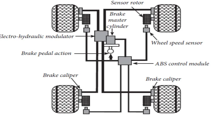
[image:2.595.113.482.199.401.2]motivation behind controller planned in the car framework is to manage the wheel speed. Control strategies of Antilock Braking system are also functional in vehicle dynamic stability control (VDSC), Electronic Stability Control (ESC) and traction control system (TCS) [14]. Normal ABS parts include: wheel speed sensors, vehicle's physical brakes, brake ace chamber, an electronic control unit (ECU), brake ace chamber, a water driven modulator unit with pump and valves as appeared in Figure.1.
Figure 1. Typical Components of Anti-lock Braking System [15]
a portion of the propelled ABS Systems incorporate accelerometer to decide the deceleration of the vehicle[16]. In the present situation there is a relentless rivalry among various vehicle producing businesses for receiving propelled innovations to enhance the dynamicity of the vehicles. Due to this the security of the driving personnel and the fast growing traffic is at stake. For the sanctuary of the above the appropriate process of the braking entity is roughly necessary in an automobile system. Brakes are some sort of transducers, which changes over the dynamic vitality of vehicle into warm vitality. This development of exchange has made many researchers in the region of the globe to accept many sophisticated techniques to get better breaking progression. Out of these, Anti-bolt Braking system (ABS) is a standout amongst the most regularly and broadly fused innovations. ABS is the Electronically monitored slowing mechanism that is the electro-mechanical system which prevents the wheels from locking and subsequently sliding. Later on in the year 1970 it was introduced in four wheelers and in the year 1988 motor cycle manufacturing industries also started using it. As detailed by an Australian investigation in Monash University Accident Research Center in 2014, the danger of numerous vehicle crashes is lessened by 24% and the danger of overflow street crashes is decreased by 41% [17].Even though, Anti-bolt Braking System has been actualized in present day automobiles, still the ABS innovation is having significance and giving critical change to the cutting edge interms of a modern safety. The ABS progression and additionally the road- tire rubbing model being exceptionally nonlinear, random and time fluctuating, demonstrating and improvement of ABS is
extremely a fastidious exertion.To the extent auto- industry is concerned, the ABS innovation is the latest advancement in improving traveler wellbeing or to be exact, mishap evasion. Specifically an essential part of ABS is the understanding of friction model. Consequently the study of friction force characteristic at the road tire boundary is of extreme importance for the scheming of ABS. furthermore, the friction models are vital for precisely Reproducing resistance force for replication purpose [18-25].
[image:2.595.324.549.562.720.2]2. BLOCK DIAGRAM OF ANTILOCK BRAKING SYSTEM
There are various ABS systems different from each other by their arrangement which cause difference in their effectiveness and price. One type of such systems regulates braking force for every wheel separately which is useful in conditions of multistructured road, for instance, in situation when two wheels are on dry surface and other two on wet. The most ordinary and the cheapest systems control only rear wheels velocity, while the most widespread ABS systems have sensors at every wheel. Usually these type of systems regulate braking force separately for rear and front
[image:3.595.82.515.220.376.2]wheels. Each Antilock Braking System comprises of hydraulic modulator, a wheel-speed sensor and an Electronic Control Unit (ECU). Wheels’ sensors receive information as electromagnetic induction works. After that wheel’s velocity data are delivered to the control module where this information is processed. If it is necessary, the signal for decreasing the brake pressure will be sent to hydraulic module, so that the wheels will not get blocked. Hydraulic module reduces/stops liquid supply for the braking cylinder until wheels get certain speed. The control under braking force stops when the danger of locked wheels is passed or the vehicle is full-stopped[26].
Figure 3. Block Diagram of Antilock Braking System
3. ABS CONTROL TECHNIQUES
A example of the research done for various control approaches is shown in Figure 4.One of the advancements that has been connected in the diverse parts of ABS control is delicate processing. Brief survey of thoughts of delicate processing and how they are occupied with ABS control are given beneath [27-30].
Figure 4. ABS control Techniques
a. Classical Control Method
The PID control calculation, as a kind of the classical control technique, is generally utilized as a part of process control as a result of smaller measure of estimation, better constant and simple to actualize, etc.However, there are some shortcomings also, such as that the parameter is inconvenient to modify and cannot be self-tuning, for the PID control algorithm. The effects of traditional PID control will be difficult to achieve the desired objectives as the non-linear, time-varying and other uncertainties in cornering with braking. But the model of complex non-linear object can be created by neural networks, and the best PID
[image:3.595.73.522.478.615.2]b. Optimal Control Method
The ideal control of nonlinear system, for example, ABS is a standout amongst the most difficult and difficult subjects in control theory. best possible control based on dynamic and transitory factors between tire -wheel and vehicle for a passenger car. In particular, to improve ABS braking stopping distance performance, by considering the advantage of the load transfer effect between tire/wheel and vehicle systems. A fifth order vehicle model with nonlinear tires and vehicle dynamic load transfer is, then, considered. To minimize ABS braking stopping distance, an optimal control problem is solved that consists of finding a sequence of optimal braking torque control profiles for each wheel that minimizes traveled distance. The numerical global optimal solution is obtained through a nonlinear dynamic programming (DP) algorithm. The challenge is that the method is very resource intensive, and an appropriate discretization of the vehicle model, as required by the DP, is a nontrivial task [32-36].
c. Nonlinear Control Method
The unpredictable idea of ABS requiring input control to acquire a desired system characteristic also gives rise to dynamical systems. Ting and Lin [37] developed the antilock braking control system incorporated with dynamic suspensions connected to a quarter auto model by utilizing the nonlinear backstopping configuration plans. In crisis, despite the fact that the braking distance can be lessened by the control torque from plate/drum brakes, the braking time and distance can be additionally enhanced if the typical force produced from dynamic suspension systems is thought about all the while. Singular controller is intended for every subsystem and an incorporated calculation is built to arrange these two subsystems. As a result, the incorporation of anti-lock braking and dynamic suspension systems certainly enhances the system performance, because of the reduction of braking time and distance.
d. Robust Control Method
Sliding mode control is a critical strong control approach. For the class of systems to which it applies, sliding mode controller configuration gives a deliberate way to deal with the issue of keeping up dependability and steady execution despite demonstrating imprecision. on the other hand, by permitting the tradeoffs amongst demonstrating and execution to be measured in a straightforward manner, it can light up the entire plan process[38-39]. A few outcomes have been distributed coupling the ABS issue and the VSS outline method [40,41]. In these works plan of sliding-mode controllers under the supposition of knowing the ideal estimation of the objective slip was presented. An issue of concern here is the absence of direct slip estimations. In every past examination the partition approach has been utilized. The issue was isolated into the problem of ideal slip estimation and the issue of following the assessed ideal esteem. J.K. Hedrick, et al. [42,43] proposed a change of the method known as sliding mode control. It was picked because of its power to its robustness to modeling errors and disturbance rejection capabilities. Simulation results are exhibited to delineate the capacity of a vehicle utilizing this controller to take after a coveted speed direction while keeping up consistent dividing between vehicles. Along
these lines a sliding mode control calculation was executed for this application.
e. Adaptive Control Method
Ting and Lin [44] suggested an method to include the wheel slip constraint as a priori into control design so that the skidding can be prevented. A control arrangement of wheel torque and wheel steering is planned to renovate the creative problem to that of state regulation with input limitation. For the altered problem, a low-and-high gain procedure is useful to construct the guarded controller and to enhance the operation of the wheel slip under constraint. Simulation shows that the projected control scheme, during tracking on a snow road, is capable of limiting the wheel slip, and has a acceptable synchronization between wheel torque and wheel steering.
f. Intelligent Control Method
An anti-lock braking system (ABS) is one of the main car attributes, which due to its efficient safety and driving comfort has rapidly become a mandatory feature in each personal car. During the heavy braking process the vehicle wheel velocity abruptly drops to zero providing so called wheel lock. Steering is impossible with the locked wheel, what causes the lateral instability, in other words the loss of the transport control. It is therefore begun to be important to avoid the wheel lock (preserve the vehicle control) and stop the vehicle as fast as feasible. An ABS aim is to provide a rapid transport stop to avoid the collision with other traffic objects whereas keeping the tire slip as low as necessary. In recent years many universities and independent research and development centers in cooperation with the vehicle manufacturers have been working on an ABS control algorithm design[45].
4. SLIP CONTROL USING BANG-BANG CONTROLLER
Mathematical demonstrating is the first and most essential errand in building up a control calculation for the antilock braking system, on the other hand, modeling an antilock braking system is actually a difficult task, by considering the ABS dynamics being highly nonlinear and time dependent. In any case, in this examination, a disentangled model for controller design and Processor simulation is used. The road- tire grating model is given as the Magic formula describing the nonlinear connection between attachment coefficient and wheel slip.
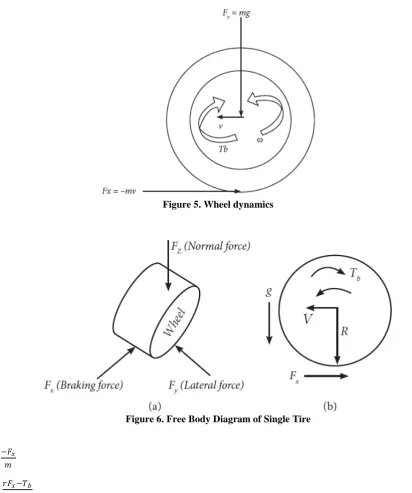
the friction between the tire surface and the street surface. The tire response force will produce a torque that outcomes in a moving movement of the wheel causing a angular velocity ω . A brake torque applied to the wheel will act
[image:5.595.79.492.107.601.2]against the turning of the wheel causing a negative precise increasing speed. The dynamics equations for the movement of the vehicle are
Figure 5. Wheel dynamics
Figure 6. Free Body Diagram of Single Tire
𝑣𝑣̇
=
−𝐹𝐹𝑥𝑥𝑚𝑚
(1)
𝜔𝜔̇
=
𝑟𝑟𝐹𝐹𝑥𝑥−𝑇𝑇𝑏𝑏𝐽𝐽
(2)
where, m is mass of the vehicle, v is vehicle speed, 𝜔𝜔 is angular speed of the wheel, Fx is tyre friction force, Tb is brake torque, r
is wheel radius and J is wheel inertia. Fz is vertical force as follows,
𝐹𝐹
𝑧𝑧=
𝑚𝑚𝑚𝑚 (3)
The tire friction force 𝐹𝐹𝑥𝑥 is given by
𝐹𝐹
𝑥𝑥=
𝐹𝐹
𝑍𝑍𝜇𝜇(𝜆𝜆)
(4)
where the friction coefficient μ is a nonlinear function of 𝜆𝜆longitudinal tyre slip that is defined by𝜆𝜆
= 1
−
𝜔𝜔𝑟𝑟𝑣𝑣(5)
and describes the normalized difference between the vehicle speed 𝜈𝜈 and the speed of the wheel perimeter 𝜔𝜔𝑟𝑟. The slip value of λ
5. SLIDING MODE CONTROLLER
A Sliding Mode Controller (SMC) is a Variable Structure Controller (VSC). Mainly, a VSC incorporates various distinctive consistent capacities that guide plant state to a control surface, and the exchanging
among various capacities is dictated by plant state that is represented by an exchanging function. Without lost of all inclusive statement, consider the design of a sliding mode controller for the following second order system:
𝑥𝑥̇=𝑓𝑓(𝑥𝑥,𝑡𝑡) +𝑏𝑏𝑢𝑢(𝑡𝑡) (6)
Here, we assume 𝑏𝑏> 0. 𝑢𝑢(𝑡𝑡) is the input to the system. The following is a possible choice of the structure of a sliding mode controller
𝑢𝑢=−𝑘𝑘𝑠𝑠𝑚𝑚𝑠𝑠(𝑠𝑠) +𝑢𝑢𝑒𝑒𝑒𝑒 (7)
Where 𝑢𝑢𝑒𝑒𝑒𝑒 is called equivalent control which is used when the system state is in the sliding mode[59]. 𝑘𝑘 is a constant, representing the maximum controller output. S is called switching function because the control action switches its sign on the two sides of the switching surface 𝑠𝑠= 0 𝑜𝑜𝑟𝑟𝑠𝑠=
𝑒𝑒. where 𝑒𝑒=𝑥𝑥 − 𝑥𝑥𝑑𝑑𝑎𝑎𝑠𝑠𝑑𝑑𝑥𝑥𝑑𝑑 is the desired state. 𝜆𝜆 is a constant. The definition of ′𝑒𝑒′here requires that 𝑘𝑘 in (1) be
positive. Sgn(s) is a sign function, which is defined as:
𝑠𝑠𝑚𝑚𝑠𝑠(𝑠𝑠) =�−1, 1,𝑖𝑖𝑓𝑓𝑖𝑖𝑓𝑓 𝑠𝑠𝑠𝑠< 0> 0 (8) The control strategy adopted here will guarantee a system
trajectory move toward and stay on the sliding surface
𝑠𝑠= 0 from any initial condition if the following condition meets:
𝑠𝑠𝑠𝑠 ≤ 𝜂𝜂|𝑠𝑠| (9) Where 𝜂𝜂a positive constant that guarantees the system trajectories is hit the sliding surface in finite time.
Using a sign function often causes chattering in practice. One solution is to introduce a boundary layer around the switch surface:
𝑢𝑢=−𝑘𝑘𝑠𝑠𝑎𝑎𝑡𝑡(𝑠𝑠) + 𝑢𝑢𝑒𝑒𝑒𝑒 (10)
𝑠𝑠𝑎𝑎𝑡𝑡(𝑠𝑠) is a saturation function that is defined as:
𝑠𝑠𝑎𝑎𝑡𝑡(𝑠𝑠) =�𝑠𝑠𝑚𝑚𝑠𝑠𝑠𝑠(𝑠𝑠,), 𝑖𝑖𝑓𝑓 |𝑖𝑖𝑓𝑓𝑠𝑠| |≤𝑠𝑠1| > 1 (11) This controller is really a persistent estimate of the perfect
transfer control. The outcome of this control plot is that invariance property of sliding mode control is lost. The system robustness is a function of the limit layer. A variation of the above controller structures is to utilize a hyperbolic tangent function rather than an saturation function [46].
𝑢𝑢=𝑘𝑘tanh�0.05𝑠𝑠 �+𝑢𝑢𝑒𝑒𝑒𝑒 (12)
It is proven that if k is large enough, the sliding model controllers of (7), (11) and (12) are guaranteed to be asymptotically stable.
6. CONCLUSION
Antilock Braking System is an example of closed loop control system used to avoid the wheel lock. Here, an attempt is made to explore, the distinct non linear control features of ABS. maintaining a desired value of vehicle slip is highly nonlinear, time dependent and random control problem due to the complex relations employed between its components and parameters. The major properties of the Non Linear controller are analyzed and examined by taking into consideration of important sensible aspects of the slip
control problem. The examine that has been carried out in ABS control systems includes a broad range of complication and challenges. Antilock Braking System with various dissimilar control methods have been developed and investigated on enhanced control methods are continuing. The majority of these approaches entail system models, and few of them cannot accomplish acceptable performance under the changes of a variety of road circumstances.
REFERENCES
[1] P.M. Hart, “Review of Heavy Vehicle Braking Systems Requirements (PBS Requirements),” Draft Report, 2003. [2] M. Maier and K. Muller “The New and Compact ABS Unit
for Passenger Cars, ” SAE Paper No.950757, 1996.
[3] P. E. Wellstead and N. B. O. L. Pettit, “Analysis and Redesign of an Antilock Brake System Controller,” IEEE Proceedings Control Theory Applications, Vol. 144, No.5, 1997, pp. 413-426. DOI.10.1049/ip-cta:19971441
[4] A. G. Ulsoy and H. Peng, “Vehicle Control Systems,” Lecture Notes, ME 568, 1997.
[5] P.E. Wellstead, “Analysis and Redsign of an Antilock Brake System Controller,” IEEE Proceedings Control Theory Applications, Vol. 144, No. 5, 1997, pp. 413-426 DOI.10.1049/ip-cta:19971441
[6] R. Fling and R. Fenton, “A Described-Function Approach to Antiskid Design,” IEEE Transactions on Vehicular Technology, Vol. Vt-30, No. 3 ,1981, pp. 134-144. DOI:10.1109/T-VT.1981.23895
[7] S. Yoneda, Y. Naitoh and H. Kigoshi, “Rear Brake Lock-Up Control System of Mitsubishi Station,” SAE Paper, Washington, 1983.
[8] Tz. Tabo, N. Ohka, H. Kuraoka and M. Ohba, “Automotive Antiskid System Using Modern Control Theory,” IEEE Proceedings, San Francisco, 1985, pp.390-395.
[9] H. Takahashi and Y. Ishikawa, “Anti-Skid Braking Control System Based on Fuzzy Inference,” U.S. Patent No.4842342, 1989.
[10] R. Guntur and H. Ouwerkerk, “Adaptive Brake Control System,” Proceedings of the Institution of Mechanical Engineers,Vol.186,No.68.1972,pp.855-880.
DOI:10.1243/PIME PROC 1972 186 102 02
[11] G. F. Mauer, “A Fuzzy Logic Controller for an ABS Braking System,” IEEE Transactions on Fuzzy Systems, Vol.3, No.4, 1995, pp.381-388. DOI:10.1109/91.481947
[12] W. K. Lennon and K.M Passino, “Intelligent Control for Brake Systems,” IEEE Transactions on Control Systems Technology, Vol. 7, No. 2, 1999, pp.188-202.
[13] B. Lojko and P. Fuchs, “The Control of ASR System in a Car Based on the TMS320F243 DSP,” Diploma Thesis, Dept. of Radio & Electronics, Bratislava, 2002.
[14] P. Hart, “ABS Braking Requirements,” Hartwood Consulting Pty Ltd, Victoria, 2003.
[15] Presentation on theme: “Chapter 73 Antilock Brakes, Traction Control, and Stability Control,”-Presentation transcript:
[16] A. Ayman, El-Shafei Zeindan, Ahmed Hamed, Farhan Salem, “An Antilock- Braking Systems (ABS) Control: A Technical Review,” Intelligent Control and Automation,
2011,2,186-195 DOI:10.4236/ICA.2011.23023.
[17] Budd Laurie, and Newstead Stuart, “Potential Safety Benefits of Emerging Crash Avoidance Technologies in Australasian Heavy Vehicles,” Report No. 324, 2014. [18] S. Champatiray, Saswata, Senapati Rajendra, K. Rout
[19] G. F. Mauer, “A Fuzzy Logic Controller for an ABS Braking Systems,” IEEE Transactions on Fuzzy Systems, Vol.3, No. 4, 1995, pp.381-388. DOI: 10.1109/91.481947
[20] J. Song, H. Kim and K. Boo, “A study on an Anti-Lock Braking System Controller and Rear-Wheel Controller to Enhance Vehicle Lateral Stability,” Proceedings of the Institution of Mechanical Engineers, Part D: Journal of Automobile Engineering, Vol. 221 No. 7, 2007, pp. 777- 787. DOI: 10.1243/09544070JAUTO225.
[21] F. Jiang, “An Application of Nonlinear PID Control to a Class of Truck ABS Problems,” Proceedings of the 40th IEEE Conference on Decision and Control, Orlando, 2000, pp. 516-521.
[22] M. Tanellia, A. Astolfi and S. M. Savaresi, “Robust Nonlinear Output Feedback Control for Brake by Wire Control Systems,” Automatica, Vol. 44, No. 4, 2008, pp. 1078-1087. DOI:10.1016/j.automatica.2007.08.020
[23] R. Freeman, “Robust Slip Control for a Single Wheel,” University of California, Santa Barbara, 1995.
[24] J. S. Yu, “A Robust Adaptive Wheel-Slip Controller for Antilock Brake System,” Proceedings of 36th IEEE Conference on Decision Control, San Diego, 1997, pp. 2545-2546.
[25] J. Yi, L. Alvarez, R. Horowitz and C. C. DeWit, “Adap-tive Emergency Braking Control Using a Dynamical Tire/Road Friction Model,” Proceedings of 39th IEEE Conference on
Decision Control, Sydney, 2000, pp. 456- 461.
[26] J. Lüdemann, “Heterogeneous and Hybrid Control with Application in Automotive Systems,” Ph.D. dissertation, Glasgow University, 2002.
[27] Y. Liu and J. Sun, “Target Slip Tracking Using Gain-Scheduling for Braking Systems,” Proceedings of the 1995 American Control Conference, Seattle, 1995, pp. 1178-1182. [28] S. Taheri and E. H. Law, “Slip Control Braking of an
Automobile during Combined Braking and Steering Manoeuvres,” American Society of Magazine Editors, Vol. 40, No. 1, 1991, pp. 209-227.
[29] C. Jun, “The Study of ABS Control System with Different Control Methods,” Proceedings of the 4th International Symposium on Advanced Vehicle Control, Nagoya, 1998, pp. 623-628.
[30] F. Jiang, “A Novel Approach to a Class of Antilock Brake Problems,” Ph.D. Dissertation, Cleveland State University, Cleveland, 2000.
[31] Y. Wang, T. Schmitt-Hartmann, M. Schinkel and K. J. Hunt, “A New Approach to Simultaneous Stabilization and Strong Simultaneous Stabilization with D Stability and Its
Application to ABS Control Systems Design,” European Control Conference, Porto, 2001, pp. 1291- 1294.
[32] S. Solyom, “Synthesis of a Model-Based Tire Slip Controller,” Synthesis of a Model-Based Tire Slip Controller, Vol. 41, No. 6, 2004, pp. 475-499.
[33] S. Drakunov, Ü. Özgüner, P. Dix, and B. Ashrafi, “ABS Control Using Optimum Search via Sliding Modes,” IEEE
Transactions on Control Systems Technology, Vol. 3, 1995, pp. 79-85. DOI:10.1109/87.370698
[34] M. Schinkel and K. Hunt, “Anti-lock Braking Control Using a Sliding Mode Like Approach,” Proceedings of the 2002 American Control Conference, Anchorage, 2002, pp.
2386-2391.
[35] M. C. Wu and M. C. Shih, “Hydraulic Anti-Lock Braking Control Using the Hybrid Sliding-Mode Pulse Width Modulation Pressure Control Method,” Proceedings of the Institution of Mechanical Engineers, Vol. 215, 2001, pp. 177-187. DOI:10.1109/87.748153
[36] C. Ünsal and P. Kachroo,“Sliding Mode Measurement Feedback Control for Antilock Braking Systems,” IEEE Transactions on Control Systems Technology, Vol. 7, No. 2, March 1999, pp. 271-281.
[37] W. Ting and J. Lin, “Nonlinear Control Design of Anti-lock Braking Systems Combined with Active Suspensions,” Technical report of Department of Electrical Engineering, National Chi Nan University, 2005.
[38] R.-G. Wang, Z.-D. Liu and Z.-Q. Qi, “Multiple Model Adaptive Control of Antilock Brake System via Back-stepping Approach,” Proceedings of 2005 International Conference on Machine Learning and Cybernetics, Guangzhou, 2005, pp. 591-595.
[39] T. A. Johansen, J. Kalkkuhl, J. Lüdemann and I. Petersen, “Hybrid Control Strategies in ABS,” Proceedings of the 2001 American Control Conference, Arlington 2001, pp. 1704-1705.
[40] H. S. Tan and M. Tomizuka, “An Adaptive Sliding Mode Vehicle Traction Controller Design,” Proceedings of the 1989 American Control Conference, Pittsburgh, 1989, pp. 1053-1058.
[41] Y. K. Chin, W. C. Lin and D. Sidlosky, “Sliding-Mode ABS Wheel Slip Control,” Proceedings of 1992 ACC, Chicago, 1992,pp. 1-6.
[42] J. C. Gerdes, A. S. Brown and J. K. Hedrick, “Brake System Modeling for Vehicle Control,” Proceedings International Mechanical Engineering Congress and Exposition, San
Francisco, 1995, pp. 4756-4763.
[43] D. Cho and J. K. Hedrick, “Automotive Power train Modeling for Control,” Transactions ASME Journal of Dynamic Systems, Measurements and Control, Vol.111, No.4, December 1989, pp. 568-576. DOI:10.1115/1.3153093 [44] E. Kayacan and O. Kaynak, “A Grey System Modeling
Approach for Sliding Mode Control of Antilock Braking System,” IEEE Transactions On Industrial Electronics, Vol. 56,No.8,August2009,pp.3244-3252.
DOI:10.1109/TIE.2009.2023098
[45] W. Ting and J. Lin, “Nonlinear Control Design of Anti-lock Braking Systems Combined with Active Suspensions,” Technical Report of Department of Electrical Engineering, National Chi Nan University, 2005.
[46] M. Schinkel and K. Hunt, “Anti-lock Braking Control Using a Sliding Mode Like Approach,” Proceedings of the 2002 American Control Conference, Anchorage, 2002, pp.