ISSN (Print) : 2320 – 3765 ISSN (Online): 2278 – 8875
I
nternational
J
ournal of
A
dvanced
R
esearch in
E
lectrical,
E
lectronics and
I
nstrumentation
E
ngineering
(An ISO 3297: 2007 Certified Organization)
Vol. 5, Issue 3, March 2016
Hardware Implementation of Smart Reader
for Visually Impaired People Using
Raspberry PI
Velmurugan.D1, Srilakshmi2, Umamaheswari.S3, Parthasarathy.S4, Arun.K.R5
Assistant Professor, Department of Electrical and Electronics Engineering, Info Institute of Engineering, Kovilpalayam,
Coimbatore, India1
UG Students, Department of Electrical and Electronics Engineering, Info Institute of Engineering, Kovilpalayam,
Coimbatore, India 2, 3.4.5,6
ABSTRACT: This work proposes the novel implementation of smart book reader with raspberry pi controller. In olden days more no of people are suffered with visually impaired. In particular, there is a need for a portable text reader that is affordable and readily available to the blind community. Inclusion of the specially enabled in the IT revolution is both a social obligation as well as a computational challenge in the rapidly advancing digital world today. This work proposes a smart reader for visually challenged people using raspberry pi. This paper addresses the integration of a complete Text Read-out system designed for the visually challenged. The system consists of a webcam interfaced with raspberry pi which accepts a page of printed text. The proposed system is simulated under Matlab software. In this MATLAB with the help of image processing toolbox OCR (Optical Character Recognition) is performed with text to speech algorithm. A sample image converted with each pixel by pixel and pixels are converted with binary “0” and “1” conversion, segmentation and labeling, Synthesizer, the sample image text document converted with speech which is heard by headset. The experimental results are done with the help of raspberry pi controller. Controller coding for the Raspberry pi is done through PYTHON language. The audio output is obtained after the captured image is converted to text. The image captured by the camera is converted to text and displayed in the form window and then the text is obtained as audio output. Raspberry pi has the audio port where the output can be heard through the headphone or the speaker. Once the image is converted to text raspberry pi takes few milli seconds to convert it as a voice output. The proposed system is under validated with both simulation and experimental verification it achieves the text document is converted with speech for the use of visually impaired people.
KEYWORDS: Raspberry pi, Web Cam, Optical character recognition, Text to Speech Engine, Audio amplifier.
I. INTRODUCTION
Optical Character recognition is useful for visually impaired people who cannot read Text document, but need to access the content of the Text documents. It is used to digitize and reproduce texts that have been produced with non-computerized system. Digitizing texts also helps reduce storage space. Editing and Reprinting of Text document that were printed on paper are time consuming and labour intensive. This paper is on Methodology of a camera based device that can be used by people to read any Text document. The framework is on implementing image capturing technique in an embedded system based on Raspberry Pi board.
II. BLOCK DIAGRAM OF PROPOSED METHOD
ISSN (Print) : 2320 – 3765 ISSN (Online): 2278 – 8875
I
nternational
J
ournal of
A
dvanced
R
esearch in
E
lectrical,
E
lectronics and
I
nstrumentation
E
ngineering
(An ISO 3297: 2007 Certified Organization)
Vol. 5, Issue 3, March 2016
Figure.1 Block Diagram of Proposed Method
The power supply is given to the 5V micro USB connector of raspberry pi through the Switched Mode Power Supply (SMPS). The SMPS converts the 230V AC supply to 5V DC. The web camera is connected to the USB port of raspberry pi. The raspberry pi has an OS named RASPION which process the conversions. The audio output is taken from the audio jack of the raspberry pi. The converted speech output is amplified using an audio amplifier. The Internet is connected through the Ethernet port in raspberry pi. The page to be read is placed on a base and the camera is focused to capture the image. The captured image is processed by the OCR software installed in raspberry pi. The captured image is converted to text by the software. The text is converted into speech by the TTS engine. The final output is given to the audio amplifier from which it is connected to thespeaker. The speaker can also be replaced by a headphone for convenience
.
III. SIMULATION ENVIRONMENT
3.1 MATLAB SIMULATION FOR VOICE OUTPUT
ISSN (Print) : 2320 – 3765 ISSN (Online): 2278 – 8875
I
nternational
J
ournal of
A
dvanced
R
esearch in
E
lectrical,
E
lectronics and
I
nstrumentation
E
ngineering
(An ISO 3297: 2007 Certified Organization)
Vol. 5, Issue 3, March 2016
Figure.3 Flow of process of simulation
SCANNED IMAGE
ENHANCED IMAGE
CHARACTER SEGMENTATION
FEATURE EXTRACTION
IMAGE TO TEXT CONVERTER
NORMALISED TEXT DOCUMENT
SYNTHESISED SPEECH
ISSN (Print) : 2320 – 3765 ISSN (Online): 2278 – 8875
I
nternational
J
ournal of
A
dvanced
R
esearch in
E
lectrical,
E
lectronics and
I
nstrumentation
E
ngineering
(An ISO 3297: 2007 Certified Organization)
Vol. 5, Issue 3, March 2016
Fig.2 represents the simulation of OCR in MATLAB.Since MATLAB cannot simulate a complete sentence, individual word is being simulated. A sample image is taken and it is captured using the USB camera. The OCR is simulated by four processes in MATLAB
1. Binary Representation 2. Area and Edge process 3. Segmentation and labelling 4. Character skeleton
Binary representation converts the captured image to machine language which is represented in 0’s and 1’s.Binay 0 represents the black colour of the characters and binary 1 represents the white colour of the characters. A boundary for each character is created in area and edge process. The boundary for each character is programmed and it can vary from 0 to 255 bits of characters occupying memory in database. The isolated blocks of characters are segmentedand
are automatically labelled. The character skeletonisation reduces the foreground regions in the binary image to a skeleton remnant. The Fig.3 represents the Flow of process of OCR conversion.
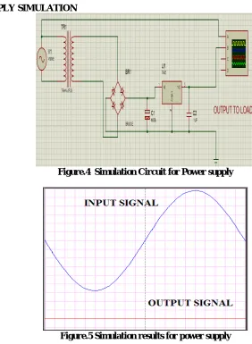
3.2 POWER SUPPLY SIMULATION
Figure.4 Simulation Circuit for Power supply
Figure.5 Simulation results for power supply
ISSN (Print) : 2320 – 3765 ISSN (Online): 2278 – 8875
I
nternational
J
ournal of
A
dvanced
R
esearch in
E
lectrical,
E
lectronics and
I
nstrumentation
E
ngineering
(An ISO 3297: 2007 Certified Organization)
Vol. 5, Issue 3, March 2016
circuit is LC filter, but practically inductor is not used because it is bulky. The value of capacitor depends upon the output voltage and output current
The figure 5 illustrates the input and output waveforms for SMPS. The input to the SMPS is a sine wave ie., ac input of 230V,50Hz. The output is a dc wave of magnitude 5V. Thus the required voltage of 5V is obtained to operate the raspberry pi board.
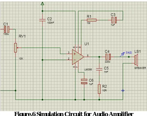
3.3 AUDIO AMPLIFIER SIMULATION:
A Class D amplifier's high efficiency makes it ideal for portable and compact high-power applications. Many modern Class D amplifiers, however, utilize advanced modulation techniques that, in various applications, both eliminate the need for external filtering and reduce electromagnetic interference (EMI). Eliminating external filters not only reduces board-space requirements, but can also significantly reduce the cost of many portable/compact systems
Figure.6 Simulation Circuit for Audio Amplifier
In modern Class D amplifiers, the most basic topology utilizes pulse-width modulation (PWM) with a triangle-wave (or sawtooth) oscillator. The figure 6 shows a simplified block diagram of a PWM-based, half-bridge Class D amplifier. It consists of a pulse-width modulator, two output MOSFETs, and an external lowpass filter (LF and
CF) to recover the amplified audio signal. As shown in the figure, the p-channel and n-channel MOSFETs operate as
current-steering switches by alternately connecting the output node to VDD and ground. Because the output transistors
switch the output to either VDD or ground, the resulting output of a Class D amplifier is a high-frequency square wave.
ISSN (Print) : 2320 – 3765 ISSN (Online): 2278 – 8875
I
nternational
J
ournal of
A
dvanced
R
esearch in
E
lectrical,
E
lectronics and
I
nstrumentation
E
ngineering
(An ISO 3297: 2007 Certified Organization)
Vol. 5, Issue 3, March 2016
. Figure.8 Output waveform of Audio Amplifier
The switching frequency (fSW) for most Class D amplifiers is typically between 250kHz to 1.5MHz. The
output square wave is pulse-width modulated by the input audio signal. PWM is accomplished by comparing the input audio signal to an internally generated triangle-wave (or sawtooth) oscillator. This type of modulation is also often referred to as "natural sampling" where the triangle-wave oscillator acts as the sampling clock. The resulting duty cycle of the square wave is proportional to the level of the input signal. When no input signal is present, the duty cycle of the output waveform is equal to 50%.
The figure 7 illustrates the input waveform of the audio amplifier. The figure 8 illustrates the resulting PWM output waveform in accordance with varying input-signal. In order to extract the amplified audio signal from this PWM waveform, the output of the Class D amplifier is fed to a lowpass filter. The LC low pass filter shown in Figure 1 acts as a passive integrator (assuming the cutoff frequency of the filter is at least an order of magnitude lower than the switching frequency of the output stage) whose output is equal to the average value of the square wave. Additionally, the low pass filter prevents high-frequency switching energy from being dissipated in the resistive load. Assume that the filtered output voltage (VO_AVG) and current (IAVG) remain constant during a single switching period. This
assumption is fairly accurate because fSW is much greater than the highest input audio frequency.
IV. HARDWARE COMPONENTS
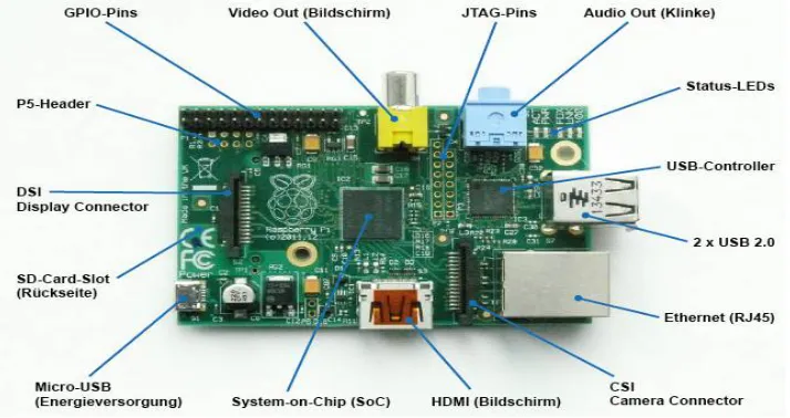
4.1 PI BOARD:
ISSN (Print) : 2320 – 3765 ISSN (Online): 2278 – 8875
I
nternational
J
ournal of
A
dvanced
R
esearch in
E
lectrical,
E
lectronics and
I
nstrumentation
E
ngineering
(An ISO 3297: 2007 Certified Organization)
Vol. 5, Issue 3, March 2016
The Raspberry pi 2 is selected as it contains 1GB RAM, Quad core processor which resembles like minicomputer. The image processing and text conversion can be done at a faster rate. It also contains Ethernet port which can be used for internet connection or remote desktop connection. It has four USB ports which is sufficient to connect devices like mouse, keyboard and memory devices. A audio jack and HDMI port are inbuilt to connect display monitors and audio speakers. The power supply is given through the micro USB port which is of 5V, 2A.
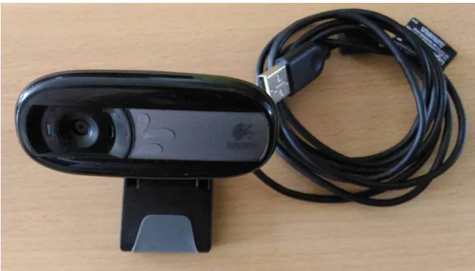
4.2 CAMERA
Figure 10 Logitech camera
Logitech 5MP USB camera is used as shown in Fig.10 in this project to get clear capture of the image. Since it is a USB camera no need of separate driver software’s and it can be used as plug and play. In Program we have controlled the ON & OFF of the camera. Once the “Click to Capture image” Button is clicked camera gets on can capture the image which it focuses after 80 frames. This 80 frame count can be changed in the program as per our requirement. The converted text from image can be heard through a headphone or a Speaker which has 3.5mm Jack.
IV. FLOW OF PROCESS OF HARDWRE
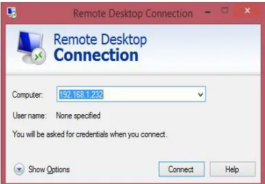
The PI Board is a minicomputer to which we can connect HDMI displays but here we connect it as a remote desktop to our laptop using Ethernet Cable. To connect PI to our laptop we must set our IP address as static IP in the same subnet of the PI Board. Then with the remote desktop option from the laptop is clicked and a dialog box appears as in Fig.11.1 The IP of PI Board is given and click connect. To login PI we must enter the username and password. After which the desktop of PI i.e., the RASPBIAN OS Desktop look as in Fig.11.2.
Task bar of this desktop has a “TERMINAL” icon, clicking on it opens a window as in Fig11.3. This is the window where we pass commands to PI. A program for this operation is written in editor window and saved with .py
ISSN (Print) : 2320 – 3765 ISSN (Online): 2278 – 8875
I
nternational
J
ournal of
A
dvanced
R
esearch in
E
lectrical,
E
lectronics and
I
nstrumentation
E
ngineering
(An ISO 3297: 2007 Certified Organization)
Vol. 5, Issue 3, March 2016
Figure 11.1 Remote Desktop connection window Figure11. 2 Login to Raspbian OS Window
Figure 11.3 Raspbian window Figure11. 4 Terminal window
Figure 11.5 Form window
Figure.11 Flow of Process
VI. CONCLUSION
ISSN (Print) : 2320 – 3765 ISSN (Online): 2278 – 8875
I
nternational
J
ournal of
A
dvanced
R
esearch in
E
lectrical,
E
lectronics and
I
nstrumentation
E
ngineering
(An ISO 3297: 2007 Certified Organization)
Vol. 5, Issue 3, March 2016
REFERENCES
[1] Mohammed hussein, Mohammed shafiek yaacob et al.. (2000) “Increasing braille literacy: voice-assisted electronic braille books(ebraille ebook) for the visually impaired journal of technology for advances in computers and education
[2] Bindu philip and r. d. sudhaker samuel2009 “Human machine interface – a smart ocr for the visually challenged” International journal of recent trends in engineering, vol no.3,november
[3] Roy shilkrot, pattie maes, jochen huber, suranga c. nanayakkara, connie k (april may 2014)“Finger reader: a wearable device to support text reading on the go”Journal of emerging trends in computing and information
[4] V. Ajantha devi1, dr. Santhosh baboo “Embedded optical character recognition on tamil text image using raspberry pi”international journal of computer science trends and technology (ijcst) – volume 2 issue 4, jul-aug 2014
[5] Prachi khilari, bhope v. (july 2015)‘Online speech to text engine”International journal of innovative research in science, engineering and technology.vol. 4, issue 7, july 2015
[6] Gopinath , aravind , pooja et.al..“Text to speech conversion using matlab”International journal of emerging technology and advanced engineering. volume 5, issue 1, (january 2015)
[7] Vikram shirol, abhijit m, savitri a et al.“DRASHTI- an android reading aid” International journal of computer science and information technologies vol.6 (july 2015)
[8] Catherine a. todd, ammara rounaq et al..“An audio haptic tool for visually impaired web users”Journal of emerging trends in computing and information science vol. 3, no. 8, aug 2012.
[9] Hay mar htun, Theingi zin, hla myo tun “Text to speech conversion using different speech synthesis” International journal of scientific & technology research volume 4, issue 07, july 2015.
[10] Jaiprakash verma, khushali desai2“Image to sound conversion “International journal of advance research in computer science and management studies research paper , volume 1, issue 6, November 2013.
[11] Dr.Vijayarani and ms.a.sakila“Performance comparison of ocr tools International journal of ubicomp(iju),vol 6,no.3,july 2015. [12] Terri hedgpeth,mike rush pe, et al (may 2015)“icare-reader - a truly portable reading device for the blind”