ZIGBEE-Based Communication System for Data Transfer with in
Future Micro grid
1B.PRATHYUSHA, 2K.ABDUL RAHAMAN
1 M.Tech., Department of ECE (DECS),Dr.K.V.Subba Reddy college of Engineering for Women, Email.Id- [email protected], Kurnool.
2 Assistant Professor, Department of ECE (DECS) Dr.K.V.Subba Reddy college of Engineering for Women, Guide Email id- [email protected], Kurnool.
Abstract—A wireless data communication system for future microgrids (MGs) is displayed in this paper. It is expected that every MG has a focal controller and each dispersed era unit in the MG has a nearby controller. The correspondence system is in charge of transmitting and accepting information among these controllers. This correspondence system depends on ZigBee innovation, which is a minimal effort and low power utilization gadget. In any case, its principle restriction is the low information exchange rate. To diminish the quantity of information exchanges, an information administration plan is introduced in this paper. The obliged information to be exchanged are characterized and a reasonable coding is proposed. At long last, the quantity of transmitted images and the preparing time of the proposed information administration plan are numerically investigated. What's more, the dynamic operation of a MG is assessed considering the defers that are forced by this correspondence system.
Index Terms—Communication system, data managementscheme, data transmission delay, microgrids (MGs), ZigBee.
I. INTRODUCTION
The Increasing Number Of Renewable Energyresources, for example, photovoltaic, wind, and smaller scale hydro are prompting to a considerable measure of electric vitality era as conveyed era (DG) units inside the electric systems. Joining of the DGs will profit the electric systems by lessening the system extension costs, minimizing the power misfortunes in long feeders and expanding the unwavering quality of the system. It might likewise be useful to accomplish speedier recuperation taking after a blame in the system [1]. Microgrid (MG) is a group of burdens, DGs and vitality stockpiles interconnected by a system of feeders and situated in the same topographical range. It can go about as an autonomous power system at whatever point
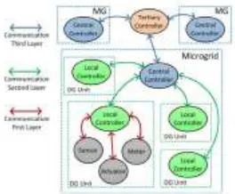
be overhauled with the data about the MG working mode. This infor-mation is required to be exchanged from the MG primary electrical switch (CB) that associates the MG and the lattice (see Fig. 1), to every one of the DGs. Also, the MG requires the ongoing force estimation of the network, burdens and DGs and the condition of charge (SoC) of the accessible vitality stockpiling gadgets. Essentially, the root mean square (RMS) esteem, stage edge, and recurrence of voltage and in addition the dynamic/responsive power at certain particular focuses in the MG are required to be observed and given as contributions to the DG control systems. Moreover, immediate estimations of voltages at the terminals of DGs and thefeeder are required for synchronizing another DG with the MG.
Fig. 1 shows a sample MG network along with the different
information which should be observed and transmitted to the particular controllers. It is normal that sooner rather than later every one of the operations in a MG will be completely computerized [2]. An examination of the attributes of the present and future MG systems is displayed in Table I. The computerization arrangement without bounds MGs incorporates bringing information from the sensors, passing the information to the controllers lastly passing the control summons to the actuators. In this way, MGs require a quick and exact information transmission system to exchange the deliberate information and charge signs to
the applicable controllers [3]. Wired and remote correspondence advances can be utilized in MGs. The prominent wired innovations, utilized as a part of force systems, are serial correspondence RS-232/422/485, transport innovation (e.g., ModBus, ProfiBus, and CANBus) [4], control line correspondence (e.g., dissemination line bearer, control line correspondence, and broadband electrical cable correspondence) [3], and Ethernet (e.g., LAN and optical link) [4], [5]. Then again, the well known remote advances, utilized as a part of force systems, are cell (e.g., worldwide system for versatile interchanges and code division different get to) [5], Wi-Fi [6], [7], WiMax [8], ZigBee [9]–[11], Z-Wave [12], Bluetooth [10], Insteon [13], radio recurrence [10], and Microwave [13]. The wired advancements have a higher information exchange transfer speed and are more dependable; be that as it may, their establishment cost is moderately high. Then again, the remote innovations have bring down establishment costs and are more reasonable for remote regions. In the meantime, they are more adaptable for future developments [10]. A correlation among various remote advances that can be considered for MG applications is introduced in Table II.
noteworthy establishment cost. Along these lines, the remote advancements are a superior possibility for MG applications. In any case, it is to be noticed that they have a lower information transmission rate and may likewise be defenseless against obstructions with different signs [7]. In this paper, a ZigBee-based correspondence innovation is proposed for information move in MGs. ZigBee has been broadly considered for information transmission in power systems. In [14], ZigBee is utilized for information observing of all subsystems of a dc MG system. It is likewise utilized for ongoing estimation and information move in a power system application in [15], where a calculation is proposed for compacting the information. The unwavering quality of ZigBee innovation in power system applications, including the quantity of good and awful information bundles transmitted under indiscreet high power homeless people, are assessed in [16]. Furthermore, an encryption code is produced for ZigBee in [9] to expand the security of the transmitted information.
Since the information exchange rate for ZigBee is low, to diminish the requirement for high information exchange by such a gadget, an information activity planning plan is proposed in [17] where the information traffics are organized into three groupings, each with littler parcel sizes. Then again, the requirement for high information transmission capacity can be decreased by utilizing a conveyed calculation as a part of a ZigBee group tree organize [18] or a multiinterface administration structure [19] or by planning information activity dissemination [20]. Usage of ZigBee as a remote sensor system is proposed in [21], in which a WiFi-ZigBee message conveyance plan is created to decrease the power utilization of the remote gadgets. Likewise, a calculation is produced in [22] to evade impedance amongst ZigBee and WiFi signals, when both are utilized as a part of force system applications. In [23], a
straightforward information coding is exhibited for ZigBee which comprises of one byte of information arrangement, two bytes of information length, and variable bytes of information itself. The constraint of this technique is that it is appropriate for exchanging just a single information. The ZigBee information payload coding has not been yet tended to for various information exchanges that are required in MGs.
In [24], ZigBee preparing time is computed to be around 400–600 μs for transmitting three unique information; be that as it may, there is no announcement of the used information coding position. In MG applications, the postponement of information transmission is pivotal and must be kept inside an adequate cutoff. Furthermore, this postponement relies on upon the used information coding and the length of information code. Since longer information codes have longer transmission delays, characterizing an appropriate and proficient information coding strategy, which speaks to all information exchanges for MG operations, is urgent. In this paper, a reasonable information payload code and an information administration plan is proposed for a ZigBee-based correspondence innovation for MGs.
What's more, the impact of the correspondence postponement is assessed on the dynamic execution of the MG. The principle commitments of this paper are as per the following:
1) proposing a ZigBee-based information correspondence innovation for MG applications;
2) building up a composed information administration conspire;
3) building up an appropriate information payload code;
MG dynamic execution within the sight of correspondence deferrals.
Whatever is left of this paper is composed as takes after. Area II examines the diverse correspondence layers required in MGs. ZigBee-based correspondence innovation for MGs is proposed in Section III. An information administration conspires for MGs is displayed in Section IV, while the information preparing deferral is examined in Section V. Some numerical outcomes are introduced in Section VI to exhibit the quantity of transmitted images and the required transmission delay in MGs. Area VII exhibits the correspondence postpone consequences for the dynamic execution of a MG. The general finish of this paperis condensed in the last area.
II. COMMUNICATION LAYERS IN MGS
A various leveled control system is required for the properoperation and control of the MG, as talked about beneath. 1) The Local (Primary) Controller: This controller is the least control obstruct inside the various leveled control
system and is situated inside each DG unit. This controller primarily controls the operation of a DG in light of its neighbourhood estimations. Consequently, it gets information from the nearby sensors/meters utilizing little inspecting time steps and delivers the required yields for the DG actuators. Amid network associated method of operation of the MG, the DG units
work in steady PQ mode and create their appraised control or work in view of most extreme power point system. In independent mode, the DGs need to work in hang control. This is quickly presented in the Appendix and talked about in points of interest in [25].
2) The MG Central Controller: This is the primary controller for the MG and is in charge of controlling the voltage greatness and recurrence in the MG. This controller gets the voltage greatness, edge, and recurrence information from the voltage sensor introduced at the MG feederand sends back the best possible references of the voltage size and point to every DG. This controller has a bigger time step contrasted with the nearby controllers and works intermittently (in ventures of a couple of minutes). Also, the exchange of the MG principle CB status to the MG focal controller falls inside this control level.
focal controller. To exchange these information to the MG focal controller, a few parameters ought to be considered in selecting and planning the correspondence innovation. They are as per the following:
1) the extent of the region in which the MG is dispersed;
2) the establishment, operational, and upkeep costs;
3) the quantity of sensors, actuators, meters, or gadgets;
4) the base information transmission rate prerequisite;
5) the information accuracy necessity;
6) the most extreme information parcel blunder prerequisite;
7) the adaptability to future extensions; 8) the accessibility of various strategies to get to information.
In light of the area of the specialized gadgets and in addition the qualities of the information to be exchanged, the correspondence innovations in the MG are grouped in three layers, as demonstrated schematically in Fig. 2. The main correspondence layer gives information exchange ability among the neighborhood controller of every DG to the sensors, meters, and actuators of the DG unit. What's more, the exchange of information from any meters/sensors introduced along the power appropriation lines or CBs to their neighborhood controllers likewise falls inside this layer. The second correspondence layer gives information exchange capacity among the nearby controllers of the DGs and the MG focal controller. This layer is the fundamental correspondence layer of the MG. The third correspondence layer is utilized to give information exchange inside a gathering of neighboring MGs [25]–[27]
This layer exchanges information between the focal controllers of the MGs and the electric system tertiary controller. This paper
concentrates on the MG second correspondence layer as it were. It is to be noticed that a decentralized control of a MG is likewise conceivable. Be that as it may, the various leveled control system talked about in this paper expands the system working abilities. Then again, usage of the various leveled control system and the required correspondence foundation expands the unpredictability of the system control and the venture costs. In this way, a techno-financial examination can be completed to characterize the harmony between the forced expenses and intricacy and the picked up advantages. This is past the extent of this exploration and is not considered in this paper
Fig. 2. Proposed hierarchical communication layer in MG.
III. ZIGBEE COMMUNICATION IN MGS
ZigBee is an emerging wireless communication technology.It has several advantages over other existing wireless communicationtechnologies which make it a better choice for MG
applications. These advantages are as follows: 1) low-cost device compared to others [16]; 2) less complexity for the users [20], [24]; 3) flexibility for expansion in future [26]; 4) possibility for multipoint interconnections [18], [19];
5) possibility of direct connection to any sensor, meter andactuator in MG [21], [23];
6) possibility of using encryption codes for enhancing thesystem security [9];
7) possibility of developing codes to prevent interferencewith other wireless communication
8) low consumption device [11], [16] and therefore suitablefor MGs that are usually in remote areas;
9) covering an area of 300–1500 m [28] which is furtherexpandable by repeaters.
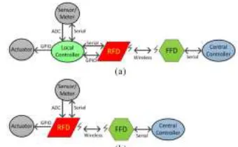
An examination between various existing remote correspondences advances and the previously mentioned attributes is introduced in Table III. From this table, it can be seen that ZigBee is the most favored innovation for future MGs. As far as correspondence capacities, there are two sorts of ZigBee gadgets, i.e., full capacity gadget (FFD) and diminished capacity gadget (RFD) [29]. A RFD has the ability to associate with sensors, actuators, and meters; be that as it may, it doesn't have the capacity to speak with different RFDs. Then again, a FFD has the ability to speak with different FFDs and in addition the sensors, actuators and meters [29]. The RFD goes about as a ZigBee end-gadget, while the FFD can go about as a switch or a facilitator. The switch is utilized for information directing or correspondence with different switches or facilitators, developing the secured zone and in addition fortifying the transmitted signs [11]. The facilitator is utilized to set up and deal with the system. The sensors/meters/actuators in one DG can be associated straightforwardly to the neighborhood controller through both of simple to-computerized converters, broadly useful input–output, or serial correspondence [23]. The got information and any handled yields can then be transmitted by the RFD, which is associated with the neighborhood controller. The transmitted information by the nearby controller of the DG will be gotten by the MG
Fig. 3. FFD and RFD utilization in the MG. (a) DG local controller connectionto MG central controller. (b) CB status and voltage/frequency data transferto central controller
is made out of various littler DGs, conveyed over an unlimited region. An illustration can be wind turbines appropriated inside a wind cultivate or various photovoltaic cells conveyed over a photovoltaic ranch. The fundamental favorable position of a multicluster topology is extending the scope zone, while its principle burden is the expansion of information dormancy [13]. Fig. 4 schematically demonstrates a case of a ZigBee-based multicluster correspondence organize for the MG. An imperative parameter to be considered in multicluster correspondence systems is the time occupation obligation
Fig. 4. ZigBee-based multicluster communication network for the MGratio (TODR) that is the time period which each ZigBeedevice can take to transmit data to the coordinator.
This dutyratio depends on the number of ZigBee-based clusters withinthe MG. Since the time allocated for each Zigbee device withinthe MG is equal, for the network of Fig. 4, TODR is calculated from
1 2 0
100 (%)
... CID CID CID
dev dev dev dev
TODR
n n n n
(1) where CID
dev
n is the number of Zigbee devices in
the same cluster while then CID 1 dev
n represents the number of Zigbee devices in its upper cluster
and 0 dev
n is the number of Zigbee devices in the coordinator's cluster(main cluster).
As an example, based on (1) for each device is the main cluster (CID=0) of Fig. 4. TODR of trasferring data is
0
100 100
25% 4
dev
TODR n
While this ratio for each device in the clusters with CID =1.0 and 2.2.1 are, respectively,
0 0
100 100
12.5%
1.0 2 4
dev dev
TODR
n n
2.2.1 2.2 2.0 0
100 100
1.04% 2 3 4 4
CID CID CID dev dev dev dev
TODR
n n n n
From this example, it is seen that the TODR of an RFDin the cluster with CID = 1.0 for transferring data to thecoordinator is 12 times higher than an RFD in the clusterwith CID = 2.2.1. Therefore, the RFDs should be placed indifferent clusters based on the importance and frequency ofdata transmission to the coordinator. Based on this concept,the RFDs which transfer data with the following characteristicsshould be placed in the 1st/2nd cluster:
1) data transmitted frequently;
2) data transmitted to the coordinator immediately;
3) data affecting the whole control system of the MG;
4) data utilized for emergency purposes.
However, the data from the RFDs with the followingcharacteristics can be placed in the farther clusters:
1) data sent for monitoring purpose only; 2) data with wide tolerance of data packet error; 3) data with low precision;
4) data affecting the local controllers only. Hence, if the data such as weather forecasting info (e.g., thesun radiation, ambient temperature, wind speed, etc.) or theSoC of the batteries need to be transferred to the MG centralcontroller, the relevant RFDs can be located in fartherclusters.
IV. DATA MANAGEMENT IN MG
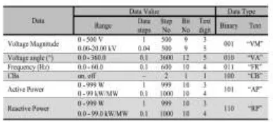
The quantity of information to be observed and moved in a MG relies on upon the quantity of the DGs inside the MG. Likewise, a few DGs may have a specific arrangement of information to be observed and transmitted, for example, the climate information. Thusly, the quantity of information to be moved in the MG can be huge. Since the information exchange rate of ZigBee is just up to 250 kbps, the information transmission in MGs ought to be deliberately overseen with the end goal that the system transfer speed can handle the information exchanges. The information administration plot proposed in this paper is in light of characterizing a reasonable time interim for transmitting the information and legitimate number of bits speaking to the information. Table IV demonstrates the proposed number of bits for every information parameter in the MG. A few information should be transmitted promptly, for example, the CB status. Be that as it may, a few information, for example, the voltage size, point, and recurrence and in addition the dynamic/responsive power can be moved in short interims of _T. This interim should be characterized in view of the impact of the information on the execution of the MG and can be in the scope of a couple of minutes. Likewise, to additionally decrease the quantity of information transmission, adequate breaking points for the information variety can be
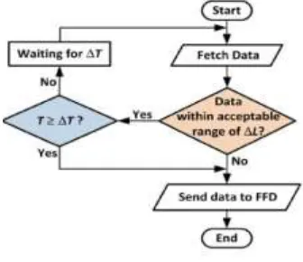
characterized with the end goal that the information are transmitted immediately just if the information surpass the characterized furthest reaches of _L. Ordinarily, as far as possible are characterized for the MG recurrence (e.g., 49.5–50.5 Hz) and the voltage extent (e.g., 90%–110% of the ostensible voltage). In view of and , the information administration flowchart for each FFD is as appeared in Fig. 5.
Fig. 5. Data management flowchart for RFDs. 3) An affirmation outline (ACK), utilized for affirming effective edge gathering; this edge is
comprised of 88 bits.
4) The medium get to control (MAC) charge outline which is utilized for taking care of all MAC peer substance control exchanges. This edge is comprised of 96 + (32 − 160) + ubits where u is the summon payload bit.
The correspondence between the FFD/RFDs and the facilitator (in nonbeacon organize) begins by the organizer asking for information from the FFD/RFDs. At that point, the RFD/FFDs affirm by transmitting an ACK and the asked for information. In the wake of getting the information, the organizer transmits the ACK to the FFD/RFDs. The schematic of this correspondence succession is outlined in Fig. 6.
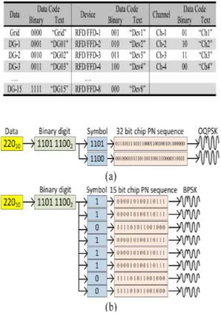
In light of IEEE Standard 802.15.4, ZigBee gadgets are accessible with 868, 915 MHz, and 2.45 GHz bearer frequencies. The lower bearer recurrence more often than not has longer region scope, e.g., the 2.45 GHz ZigBee from the Xbee-Pro from Digi International Inc., can cover a region up to 1.5 km, while the 868 and 915 MHz ZigBees from a similar producer can cover a zone up to 40 and 14.5 km, separately [28]. The information regulation procedure for the 868 and 915 MHz ZigBees is paired stage move keying (BPSK) while for the 2.45 GHz ZigBee is balanced quadrature stage move
keying (OQPSK). The information exchange rate for the 868, 915 MHz, and 2.45 GHz ZigBees is individually 20, 40, and 250 kbps [29]. In 2.45 GHz ZigBee, each 4 bits of information should be mapped into one image and every image is then mapped into a 32-bit-chip-PN grouping. In 868 and 915 MHz ZigBees, every information bit should be mapped into an image and every image is then mapped into a 15-bit-chip-PN-arrangement [29].
arrangement has more adaptability for extending the system gadgets and information exchanges in the MG. Furthermore, the parallel configuration can be straightforwardly changed over to the image and after that into OQPSK or BPSK modulator, though the content arrangement first should be changed over into double code utilizing the outstanding American Standard Code for Information Interchange code [30] and after that into an image.
Fig. 7. Example illustrating the steps of modulating ―220 V‖ in ZigBee witha carrier frequency of (a) 2.45 GHz and (b) 868 or 915 MHz.
Information exchange required in the MG can be delegated takes after.
1) Data exchange where RFD sends information to FFD/facilitator.
2) Data ask for exchange, where the facilitator requestdata esteem or status from the RFD (e.g., the organizer needs information of the produced dynamic power from a DG).
3) Command exchange, where the organizer sends an order to the RFD (e.g., the facilitator demands RFD to open/close a CB).
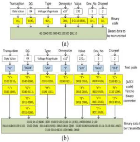
what's more, content arrangements is given in Table IV. This information payload coding is then used inside the information payload area of the standard ZigBee information outline. There are two choices to transmit the information. The principal technique depends on considering a settled number of bits or characters for every parameter. This strategy is less demanding to be perceived by system and RFD/FFDs; be that as it may, it brings about longer information bit lengths. The second technique depends on having an alternate number of bits for every parameter, contingent upon the quantity of bits or characters characterized for every parameter, as presented in Tables IV and V. The principle preferred standpoint of the second strategy is the less number of bits and henceforth a shorter preparing delay. Fig. 8(a) demonstrates the standard information outline for ZigBee where these two strategies are indicated chematically in Fig. 8(b) and (c). In this examination, both of these strategies are used and their preparing defer times are looked at. The time of information casing in ZigBee is the whole of the time of information payload and the time of other transmitted parameters, for example, prelude arrangement, begin of casing delimiter, and so on., as appeared in Fig. 8(a). For instance, let us accept a voltage sensor that is associated with channel-2 of RFD-5 in DG-4 measures a voltage greatness of 220 V. The information to be transmitted is coded as appeared in Fig. 9. From this figure, it can be seen that the 220 V estimations can be transmitted by 26 bits when
Fig. 8. (a) Standard data frame for ZigBee. (b) Proposed data payload structurefor fixed number of bits for each parameter. (c) Proposed data payloadstructure for variable number of bits for each parameter.
section of the ZigBee data frame based on theproposed (a) binary format and (b) text format.
binary format is utilized or by 152 bits when text formatis used.
By applying the above talked about information administration, the quantity of information transmission in the MG is altogether lessened without bringing on any trouble in MG typical operation.
V. INFORMATION TRANSMISSION
DELAY
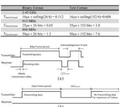
An ideal opportunity to exchange every piece by ZigBee gadgets relies on upon the information exchange rate. This time can be computed as TBit = 1/information rate. Consequently, TBit is equivalent to 4, 25, and 50 μs for the 2.45 GHz, 915, and 868 MHz ZigBee gadgets, individually. The obliged time to exchange an image (TSymbol) can be ascertained as TSymbol = TBit × number of bits in every image. Thus, TSymbol of 2.45 GHz ZigBee is TBit ×4 bits = 16 μs; notwithstanding, TSymbol when utilizing 915 and 868 MHz ZigBees are, individually, TBit × 1 bit = 25 μs and TBit × 1 bit = 50 μs. The aggregate preparing time for the information payload (TDataPayload) is computed as TDataPay load = TSymbol × ceiling_number of double digitsnumber of bits in each symbol_(2) where the quantity of bits for an image is 4 for the 2.45 GHz ZigBee and one for the 915 and 868 MHz ZigBees. For instance, the preparing time of transmitting the information payload of 220 V, appeared in Fig. 9, for ZigBees with various transporter frequencies and diverse organizations are recorded in Table VI.
Expecting least number of bits is utilized for the address fields (i.e., 32 bits in light of [29]), the aggregate preparing time for exchanging the information outline (TDataFrame) is figured as
TDataFrame = TDataPayload + TDF (3)where TDF is the handling time for alternate segments of the information outline (i.e., preface succession, begin of edge delimiter, outline length, outline control, grouping number, tending to field, and casing check arrangement segments). TDF is 480, 3000, and 6000 μs, separately, for 2.45 GHz, 915, and 868 MHz ZigBee.
Fig. 10. Schematic of data transmission in ZigBee. (a) Successful and(b) unsuccessful data transaction.
the beneficiary once more. The transmitter will retry to transmit this information most extreme of three circumstances [29]. On the off chance that the transmitter still does not get an ACK, it creates a MAC sublayer administration element COMM-STATUS sign with a status of NO_ACK [29]. The unsuccessful information transmission in ZigBee is represented as appeared in Fig. 10(b).
VI. NUMERICAL ANALYSIS RESULTS
The time delay for transmitting the numerical estimations of the estimations from sensors to the MG focal controller or information summons from the focal controller to the neighborhood controllers of every DG is of high significance. In this segment, the time postponement is ascertained and displayed as the preparing time required to exchange an information outline (TDataFrame). An illustration is
Fig. 11. Schematic of the MG network under
consideration
displayed underneath to numerically investigate the correspondence delay and the quantity of transmitted images as an element of number of DG units in a MG, ZigBee bearer frequencies, and diverse proposed information payload positions. Give us a chance to consider the MG structure of Fig. 11 with N1 converter-interfaced DGs and a couple dispersed burdens. The DGs are associated through voltage source converters (VSC) and related channels. The
point by point examination on the DG sort, VSC and channel structure and its control system are displayed in [25] and not rehashed here. The nearby controller of every DG unit transmits the normal yield dynamic and responsive force of the DG to the MG focal controller. What's more, the nearby controller of every DG unit gets the voltage and edge set-focuses from the MG focal controller. The MG focal controller likewise gets the status of the MG principle CB from the CB and the voltage greatness, point and recurrence from a voltage sensor introduced at the MG feeder. Fig. 12(a) demonstrates the examination of TDataFrame between 2.45 GHz, 915, and 868 MHz ZigBees for exchanging one arrangement of information (i.e., voltage size, voltage edge, recurrence, dynamic and responsive power, and CB status) for various number of DGs in the MG.
20 k images for every second when utilizing, individually, the 2.45 GHz, 915, and 868 MHz ZigBees. Fig. 12(c) demonstrates that the aggregate images transmitted in MG is 1112 in parallel arrangement and right around three conditions logically when using content association, for a 2.45 GHz ZigBee. This result demonstrates that when transmitting 15 sets of the already specified data, ZigBee still has the ability to trade around 56 times and 18 times more data, exclusively, in matched and substance courses of action. Fig. 12(d) shows the amount of pictures required for transmitting the already said data while using 2.45 GHz, 915, and 868 MHz ZigBees. From this figure, it can be seen that the amount of pictures required for transmitting 15 sets of the beforehand specified data while using a 868 MHz ZigBee and content game plan is close to the best uttermost ranges of ZigBee advancement.
Be that as it may, the quantity of images when utilizing 2.45 GHz and 915 MHz ZigBees in a similar organization is still, separately, 5.5% and 34.8% of as far as possible. Table VII demonstrates the handling time (i.e., TDataPayload and TDataFrame) of every information with variable and settled number of bits in the information payload segment, when utilizing 2.45 GHz ZigBee. From this table, it can be seen that when utilizing the settled number of bits for all information, TDataFrame is 0.608 (in paired configuration) or 1.088 ms (in content organization). In any case, when utilizing the variable number of bits for the information, the base TdataFrame is 0.544 (in parallel arrangement) or 0.992 ms (in content organization) while its most extreme is 0.592 (in parallel arrangement) or 1.152 ms (in content organization).
VII. COMMUNICATION DELAY EFFECT ONMG PERFORMANCE
To assess the dynamic execution of a MG comprising of converter-interfaced DGs where correspondence deferral is considered in the MG various leveled control system, a reproduction study is completed in PSCAD/EMTDC. Give us a chance to consider the MG system of Fig. 11 with just two DGs (i.e., DG1 and DG2). Give us a chance to accept that it is coveted to keep up the yield control proportion of DG1 versus DG2 as 1:2. The MG is considered at first at unfaltering state and self-governing condition, with an aggregate load request of 0.41 p.u. where 1 p.u. is 6 kVA. At t = 0.5 s, the MG load is Increased to 1 p.u. also, at t = 1 s diminished to 0.53 p.u. At t = 1.5 s, the heap is further diminished to 0.17 p.u. Taking after each heap change, the DGs upgrade their yield controls in like manner and the voltage size and recurrence in the MG feeder is altered. The MG dynamic operation and control is abridged in the Appendix. The MG parameters are recorded in Table B1 in the Reference section. A. Case-1: MG Performance Without Any Delay First, let us accept there is no correspondence delay (TDataFrame = 0). The aggregate dynamic power request of the heaps of the MG is appeared in Fig. 13(a). The yield dynamic power proportion among the two DGs is kept up as 1:2, as appeared in Fig. 13(b). The RMS of the voltage of MG feeder (VMG) is inside as far as possible for all heap changes, as appeared in
Fig. 12. Numerical analysis results. (a) TDataFrame in 2.45 GHz and 868 MHz ZigBees (fixed number of bit based). (b) TDataFrame of 2.45 GHz ZigBee.
(i.e., halfway oversaw hang control), the information correspondence system is required to exchange the yield dynamic and receptive force of every DG to the focal controller and give back the voltage size and point promptly to the DG nearby controllers. The ZigBee gadgets in the focal controller and the DG nearby controllers may transmit and get just a single information at once. Along these lines, for the MG arrangement of Fig. 11 which contains two DGs and every DG needs to transmit two information (i.e., dynamic and receptive power) and get two information (i.e., voltage size and point), the aggregate preparing time for transmitting and getting information in ZigBee
voltage and recurrence inside as far as possible, just if they are disregarded. It is to be noticed this is a discrete procedure
Fig 14. MG performance assuming 0.5 ms communicaiton delay (case-2) (a) Load active power(b) DGs active power (c) VMG RMS
Fig 15. MG performance assuming 4 ms communication delay (case-2) (a) Load active power. (b) DGs active power. (c) VMG RMS
(with a testing time of a couple of minutes. The voltage greatness and recurrence are checked in the MG feeder utilizing a voltage sensor. The aggregate correspondence delay for exchanging these two information from the voltage sensor to the MG focal controller
Fig. 16. MG performance assuming 10 ms communication delay (case-2).(a) Load active power. (b) DGs active power. (c) VMG RMS.
information and 5 ms is the entirety of holding up time and an ACK (i.e., 4400 μs from Section V).
Considering a similar preparing time when the MG focal controller exchanges back the new references for voltage greatness and point, the aggregate correspondence postponement will be no less than 2 × 38.8 ms = 77.6 ms. In any case, as this procedure has a discrete operation with an expansive time venture of couple of minutes, this deferral won't influence the system operation. D. Case-4: Communication Delay for Transferring MG Main CB Status As talked about in Section II, the status of the MG fundamental CB
ought to be promptly exchanged to the neighborhood controller of every DG so that the DGs can overhaul their operation mode if the MG changes its method of operation from system associated with self-ruling and the other way around. The CB status is required to be exchanged to the MG focal controller and the MG focal controller passes this data to the neighborhood controller of every DG quickly. In such a case, the aggregate correspondence delay for the MG arrangement of Fig. 11 with two DGs with the slowest ZigBee innovation (i.e., 868 MHz) and settled content configuration for one information is (14.4 + 5) ms = 19.4 ms. The correspondence delay incorporates transmission handling time from CB controller to MG focal controller, and transmission preparing time from MG focal controller to nearby controller of every DG. Hence, this information correspondence deferral is no less than two information exchange × 19.4 ms = 38.8 ms. It is to be noticed that this postponement won't rise if the DGs number increments in the MG.
Presently, let us consider the system of case-1. It is accepted that the MG is at first at enduring state condition and gridconnected. At t = 0.4 s,
the MG principle CB opens and it falls into self-sufficient method of operation. The arrangement of case-1 is reproduced accepting a zero and 40 ms correspondence delay for exchanging the MG fundamental CB status to the nearby controller of the DGs. The system voltage is appeared in Fig. 17. As it can be seen from this figure, the DGs dynamic operation does not bomb notwithstanding for a 40 ms delay.
Fig. 17. MG performance assuming a zero and 40 ms communication delayfor transferring MG main CB status to the local controller of DGs (case-4).(a) VMG RMS (no delay). (b) VMG RMS (40 ms delay).
CONCLUSION
The crucial point of this venture is to outline a remote climate system which empowers to screen the climate parameter in an industry by utilizing zigbee innovation and show the parameter on the PC's screen utilizing visual essential. The segments utilized as a part of the circuit are promptly accessible. The individual sub-circuits have been outlined on PCB and tried for working in the research center. The test has been performed by putting the sensor board both in an indoor and outside and the parameters are noted and checked with the simple transducers for blunders and the mistakes are extremely least. ZigBee targets applications not addressable by Bluetooth or whatever other remote standard.
remote innovation. To approach a venture like this a parallel way must be taken with respect to the hypothesis and the functional hardware, for an effective conclusion in any venture the ways must meet, and this lone happens when they are completely caught on. This is the reason a decent establishing in the nuts and bolts of Digital, Computer interfacing ports and programming in small scale controller ,visual basic6.0 dialect must be accomplished before constantly moving toward a venture this way. To begin off taking a gander at essential of remote gadget was must. This is the thing that made the general venture testing and fulfilling. The plan use for this venture is basically a significant straightforward one, and it is this effortlessness which mostly cuts it down with regards to the general dependable execution.
FUTURE SCOPE:
The zigbee innovation can be wide utilized for home and mechanical automation.It prompt to the modest remote innovation, so it can be generally utilized for low rate information exchange. It can likewise be utilized for the remote control unit like toys,etc. We got a proposed zigbee all inclusive remote controller. It requires just 200us of idleness and high productive utilization of force. Zigbee is the best for where the battery is supplanted infrequently.
REFERENCES
[1] R. H. Lasseter and P. Paigi, ―Microgrid: A conceptual solution,‖ in Proc.IEEE 35th Annu. Power Electron. Spec. Conf., Aachen, Germany, 2004,pp. 4285–4290.
[2] A. Sendin, ―Communication technologies, networks and strategiesfor practical smart grid deployments: From substations to meters,‖in Communication and Networking in Smart Grids, Y. Xiao, Ed.Boca Raton, FL, USA: CRC Press, 2012, pp. 241–275.
[3]S. Yoon, S. Jang, S. Bahk, and Y. Kim, ―Opportunistic routing for smartgrid with power line communication access networks,‖ IEEE Trans.Smart Grid, vol. 5, no. 1, pp. 303–311, Jan. 2014.
[4] C. Zhang, W. Ma, and C. Sun, ―A switchable high-speed fiber-opticring net topology and its method of high-performance synchronizationfor large-capacity power electronics system,‖ Int. J. Elect. Power EnergySyst., vol. 57, pp. 335–349, May 2014.
[5] N. Radhika and V. Vanitha, ―Smart grid test bed based on GSM,‖Procedia Eng., vol. 30, no. 2011, pp. 258–265, 2012.
[6] A. Usman and S. H. Shami, ―Evolution of communication technolgiesfor smart grid applications,‖ Renew. Sustain. Energy Rev., vol. 19,pp. 191–199, Mar. 2013.
[7] F. Gómez-Cuba, R. Asorey-Cacheda, and F. J. González-Castaño, ―Smartgrid last-mile communications model and its application to the study ofleased broadband,‖ IEEE Trans. Smart Grid, vol. 4, no. 1, pp. 5– 12,Mar. 2013.
[8] Y. Zhang et al., ―Distributed intrusion detection system in a multi-layernetwork architecture of smart grids,‖ IEEE Trans. Smart Grid, vol. 2,no. 4, pp. 796–808, Dec. 2011.
[9] T. Liu et al., ―A dynamic secret-based encryption scheme for smartgrid wireless communication,‖ IEEE Trans. Smart Grid, vol. 5, no. 3,pp. 1175–1182, May 2014.
scenarios,‖ IEEE Trans. Smart Grid,vol. 3, no. 4, pp. 2252–2261, Dec. 2012.
[11] N. C. Batista, R. Melício, J. C. O. Matias, and J. P. S. Catalão,―Photovoltaic and wind energy systems monitoring and building/homeenergy management using ZigBee devices within a smart grid,‖ Energy,vol. 49, pp. 306–315, Jan. 2013.
[12] S. Ahmad, ―Smart metering and home automation solutions for thenext decade,‖ in Proc. Int. Conf. Emerg. Trends Netw. Comput.Commun. (ETNCC), Udaipur, India, 2011, pp. 200–204.
[13] C. Deng et al., ―Terrestrial-satellite hybrid backbone communicationnetwork for smart power grid,‖ Energy Procedia, vol. 12, pp. 27–36,Sep. 2011.
[14] Y. K. Chen, Y. C. Wu, C. C. Song, and Y. S. Chen, ―Design andimplementation of energy management system with fuzzy control forDC microgrid systems,‖ IEEE Trans. Power Electron., vol. 28, no. 4,pp. 1563–1570, Apr. 2013.
[15] N. C. F. Tse, J. Y. C. Chan, W. H. Lau, J. T. Y. Poon, and L. L. Lai,―Real-time power-quality monitoring with hybrid sinusoidal and liftingwavelet compression algorithm,‖ IEEE Trans. Power Del., vol. 27, no. 4,pp. 1718–1726, Oct. 2012.
[16] F. M. Sallabi, A. M. Gaouda, A. H. El-Hag, and M. M. A. Salama,―Evaluation of ZigBee wireless sensor networks under high powerdisturbances,‖ IEEE Trans. Power Del., vol. 29, no. 1, pp. 13–20,Feb. 2014.
[17] J. Huang, H. Wang, Y. Qian, and C. Wang, ―Priority-based trafficscheduling and utility optimization for cognitive radio
communicationinfrastructure-based smart grid,‖ IEEE Trans. Smart Grid, vol. 4, no. 1,pp. 78–86, Mar. 2013.
[18] Y. Huang, A. Pang, and P. Hsiu, ―Distributed throughput optimizationfor ZigBee cluster-tree networks,‖ IEEE Trans. Parallel Distrib. Syst.,vol. 23, no. 3, pp. 513–520, Mar. 2012.
[19] H. Y. Tung et al., ―The generic design of a high-traffic advanced meteringinfrastructure using ZigBee,‖ IEEE Trans. Ind. Informat., vol. 10,no. 1, pp. 836–844, Feb. 2014.
[20] C. Tseng, ―Coordinator traffic diffusion for data-intensive Zigbeetransmission in real-time electrocardiography monitoring,‖ IEEE Rev.Biomed. Eng., vol. 60, no. 12, pp. 3340–3346, Dec. 2013.
[21] Y. Zhang and Q. Li, ―Exploiting ZigBee in reducing WiFi power consumptionfor mobile devices,‖ IEEE Trans. Mobile Comput., vol. 13,no. 12, pp. 2806–2819, Dec. 2014.
[22] P. Yi, C. Zhou, and A. Iwayemi, ―Developing ZigBee deployment guidelineunder WiFi interference for smart grid applications,‖ IEEE Trans.Smart Grid, vol. 2, no. 1, pp. 110– 120, Mar. 2011.
[23] I. Hwang, D. Lee, and J. Baek, ―Home network configuring schemefor all electric appliances using ZigBee-based integrated remote controller,‖IEEE Trans. Consum. Electron., vol. 55, no. 3, pp. 1300– 1307,Aug. 2009.
gastrointestinal tract,‖ IEEE Rev.Biomed. Eng., vol. 55, no. 6, pp. 1705–1710, Jun. 2008.
[25] F. Shahnia, R. P. S. Chandrasena, S. Rajakaruna, and A. Ghosh, ―Primarycontrol level of parallel distributed energy resources converters in systemof multiple interconnected autonomous microgrids within self-healingnetworks,‖ IET Gener. Transmiss. Distrib., vol. 8, no. 2, pp. 203–222,Feb. 2014.
[26] I. Serban and C. Marinescu, ―Control strategy of three-phase batteryenergy storage systems for frequency support in microgrids and withuninterrupted supply of local loads,‖ IEEE Trans. Power Electron.,vol. 29, no. 9, pp. 5010–5020, Sep. 2014.
[27] X. Lu, K. Sun, J. M. Guerrero, and J. C. Vasquez, ―An improved droopcontrol method for DC microgrids based on low
bandwidth communicationwith DC bus voltage restoration and enhanced current sharingaccuracy,‖ IEEE Trans. Power Electron., vol. 29, no. 4, pp. 1800– 1812,Apr. 2014.
[28] XBee/XBee-PRO RF Modules, Digi Int., Minnetonka, MN, USA, 2009.
[29] IEEE Computer Society, 1st ed. IEEE Standard 802.15.4, 2003.
[30] W. Stallings, Data and Computer Communication. Upper Saddle River,NJ, USA: Pearson Prentice Hall, 2007.